

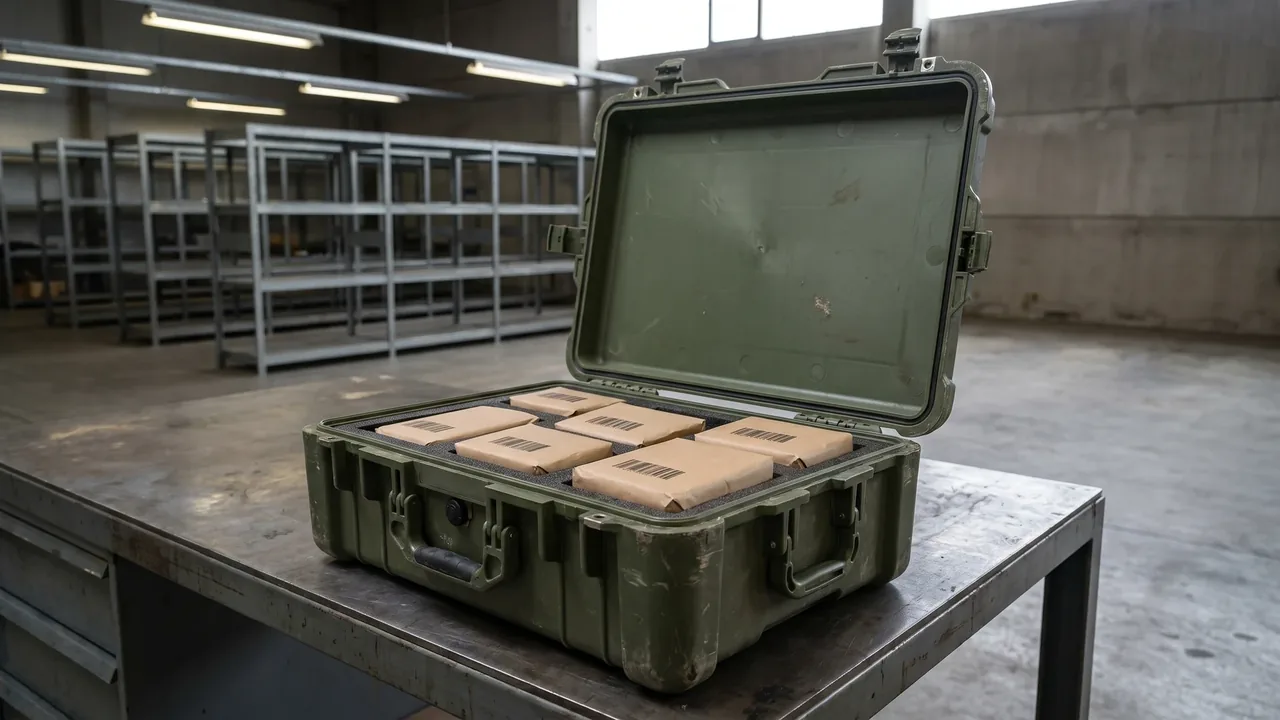
The largest difference between a Special Forces Case and an ordinary military transit case is not shell strength. It is the way the case is configured. An ordinary transit case has one job, moving a defined load safely from one point to another, and once the packing list is fixed, the interior stays the same. A mission-configured case faces a different reality: the same containers serve different missions with inventories that keep changing. One week a case carries communication gear, the next week a medical module, the week after that tools and spares. Keeping protective performance, access efficiency, and traceability intact through that much reconfiguration is what mission-configured modular layout means. This article discusses the packaging container only, covering shell, liner, zoning, latches, seals, vibration control, marking, and qualification, and says nothing about the performance of the contents.
One point belongs at the start. The transport and delivery of defense-related equipment is governed by local regulations and export control requirements, and this article discusses packaging containers only. The container and its contents follow entirely different compliance paths, and every program should have its classification judged by professional compliance staff at the outset rather than leaving that judgment to a packaging supplier. Returning to engineering, the core idea of mission configuration is to split the case into two layers. The lower layer is a common platform handling structure, sealing, stacking, and interfaces. The upper layer is a set of replaceable modules and liners carrying the specific inventory. A standardized platform with differentiated modules satisfies consistency and flexibility at the same time. A sensible program starts by fixing the platform size family and interface family, then defining modules mission by mission.
What Mission Configuration Actually Means
Thinking of the product as a single container limits the design space. It is more useful to think of it as a system made of a platform and modules. The platform includes the shell, lid, latches, sealing structure, stacking faces, and tie-down points, and none of these change between missions, so user habits around opening and securing the case stay stable. The module layer includes liner boards, trays, soft packs, and accessory fixtures, and these change with the packing list, so the user only has to adapt to a new internal arrangement rather than relearn the case. The direct benefit is lower training cost and reduced operating risk, because the platform always feels the same.
The critical constraint on this layering is a unified interface. For modules to be interchangeable between cases, they must share a mounting reference plane, locating pin positions, fastening method, and compression travel. Two approaches dominate. In the first, a standardized mounting deck sits inside the cavity and modules attach to it with common clips or fasteners. In the second, each module is itself an enclosed unit that drops into the cavity and is located by the lid's compression surface. The first offers high positioning accuracy and good vibration performance for heavier equipment; the second changes over faster and tolerates looser shell machining, which suits situations where access speed dominates. Either way, the technical document should state interface tolerances and compression force ranges, or interchangeability between production batches will erode over time. General selection criteria appear in the military protective case selection guide.
Dimensions for Splitting Modules: Mission, User, Function Chain
How modules are divided determines how usable the whole system becomes. Three dimensions dominate, each with its own emphasis. The first is mission profile: common missions are grouped and each group gets a defined module set, such as short reconnaissance, long-range movement, or extended field stay. Changeover is fast because a user simply takes the set matching a mission code, but module variety grows and inventory management becomes more complex. The second dimension is the user: modules are assigned per individual or team so each person carries their own and combinations form complete sets on demand. Distribution and accountability are straightforward, but standardization requirements are high.
The third dimension is the function chain: equipment is grouped by function such as communication, medical, tools, and power, and each function group becomes a module. This is the most universal approach, since any mission can be assembled from function modules, but it asks more of the user's judgment and therefore more training. Practice usually blends the three. Function chains define the base modules, and high-frequency missions get predefined combination packs, which shifts the burden of judgment from the user to the logistics system. There is a practical test for whether a division makes sense: count how many modules must be moved during a mission change and how long each move takes. Fewer moves and shorter times indicate that the division follows the real rhythm of use rather than a tidy drawing.
Shell Frame and Stacking System: Mechanical Compatibility Between Modules
Modularity depends on a stable mechanical frame. The frame carries load from the modules to the base bearing surface and from there to the ground, the platform, or the vehicle. A common approach places posts or ribs at the four corners of the cavity to form a continuous load ring, and modules connect to that ring through the mounting deck rather than resting directly on thin liner walls. The benefit shows up most clearly under drop and stacking loads: shock and static load travel along the frame, while modules and liners handle positioning and cushioning only, so no local overload collapses the interior.
The stacking system extends frame design. Modular systems usually operate in groups, so upper weight must pass through corners and posts while the lid carries no stacking load, or sustained pressure deforms sealing faces and shifts compression. To let different case sizes stack together, the size family should define a common module in which length and width relate by whole-number multiples, so corner bosses of upper and lower cases align. Cases should also be marked with stacking orientation and maximum stack height so users do not create overload at the bottom through casual stacking. General methods for stacking and pallet planning appear in the stackability and pallet planning reference.
Quick-Change Liners and Panels: Structural Support for Fast Conversion
Mission configuration succeeds or fails largely on conversion speed. If swapping a module requires removing ten screws, readjusting locating pins, and trial fitting repeatedly, users under pressure abandon the standard procedure and go back to stuffing items into a backpack. Quick-change structure is therefore a prerequisite rather than an optional convenience. Three forms dominate: magnetic or clip-on locating boards for light modules, slide rails with locking buttons for medium-weight modules, and fasteners with quick-release handles for heavy modules needing high vibration resistance.
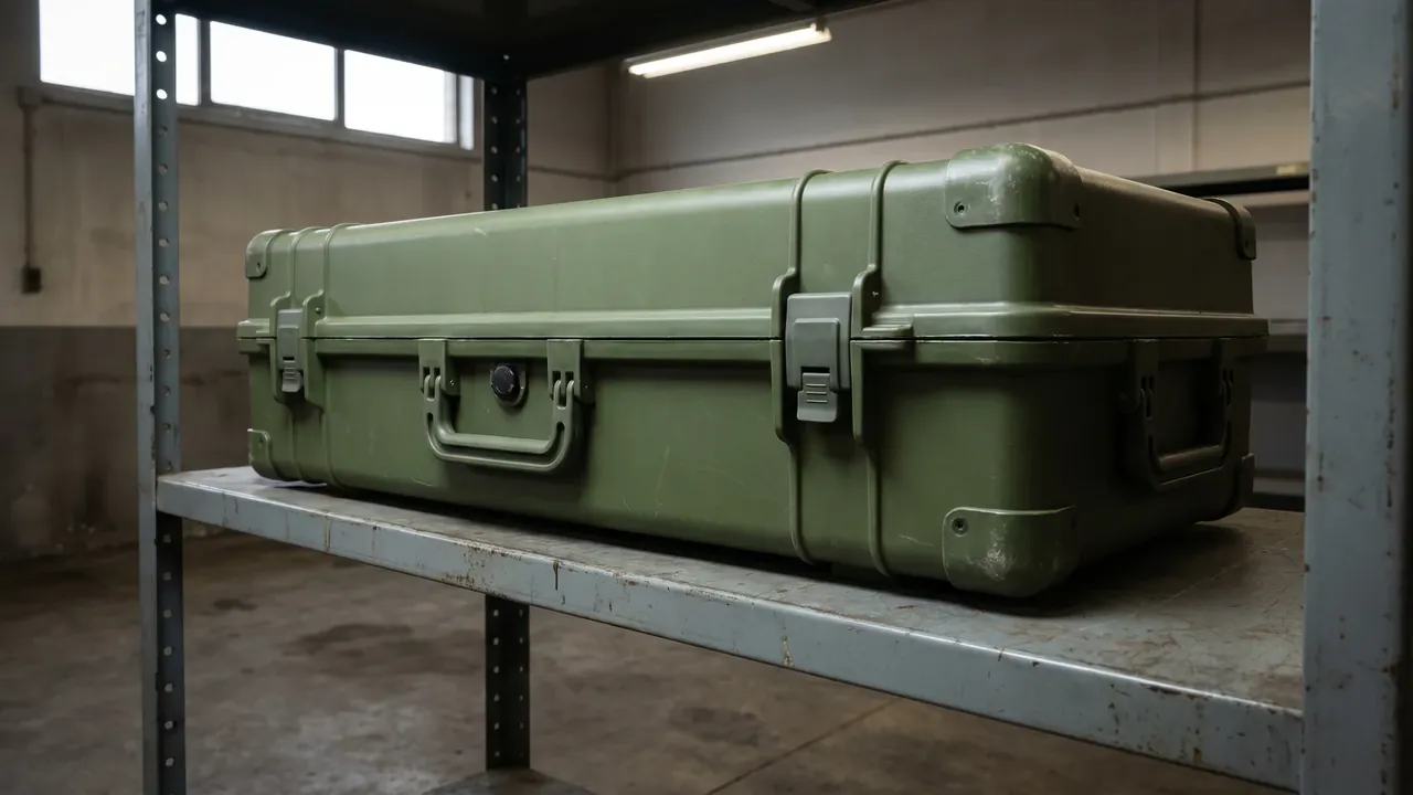
Quick-change design balances speed against reliability. Clips change fastest but can work loose under vibration and need secondary locking. Slides are fast and carry load well, but they consume space and need dust protection or grit will jam them. Quick-release fasteners are the most reliable but relatively slowest. A pragmatic approach grades by weight and frequency: clips with quick straps for frequent light modules, quick-release fasteners for infrequent heavy ones. Whatever the form, modules should be marked with installation orientation and a locked-in-place indicator, so users do not have to judge by feel whether a module is seated. Conversion speed also depends on marking and documentation. When every module carries a clear number and position diagram, a user can follow the drawing instead of relying on memory.
Carry Interfaces: Backpack Frames, Webbing, and Load-Carrying Gear
Mission cases often go where vehicles cannot, so carrying capability is a hard requirement. The central question is not whether the case can be lifted but how the load is distributed onto the human body. Medium and large cases usually travel on a backpack frame, which requires standard frame mounting points, adequate local stiffness, and a back face shaped close to the wearer. If latches or handles protrude from the back face, long carries press painfully into the back and users quickly find another way to move the load. Small cases rely on handles and shoulder straps, with handles verified at several times loaded weight and straps fitted with adjustable padding and quick release.
A frequently overlooked dimension is compatibility with the user's load-carrying gear. Users already wear harnesses, belts, and attachment points, and a case that cannot couple with them can only be carried by hand, which sharply limits range. Design options include attachment points on the case sides matching common webbing widths so the case can ride on the outside of a harness, or a detachable carry assembly that mounts quickly when needed. Interfaces should state load limits clearly so users do not attach a case to an unsuitable point and lose it. Where a case carries substantial weight, center of gravity matters for comfort, and placing heavy items toward the wearer's back is less tiring than loading the outer end.
Sealing and Protection Rating: One Baseline for Many Environments
A further advantage of mission configuration is that sealing and protection ratings can be fixed as a common platform baseline, so every module shares the same environmental protection. Whatever the mission, users know the case behaves the same. Typical baseline items include dust and water rating, operating temperature range, UV resistance, and corrosion resistance. The rating should be set from the harshest environment rather than the average, because the platform is common and cannot be downgraded for a single mission.
Sealing reliability rests on three elements: gasket material and compression, lid stiffness and even compression around the perimeter, and latch spacing and travel. Modular systems carry one extra caution: a module must not break the platform's sealing. Some designs drill through the shell to mount a module or route a cable, and if that opening has no sealing provision, the whole case rating becomes a function of the hole. The safer approach keeps mounting points inside the cavity and avoids penetrating the wall. Where a penetration is genuinely required, use a sealed feed-through and state its protection requirement separately in the technical document. For missions spanning multiple climate zones, the platform should also carry a pressure-equalization valve so differentials neither deform the gasket nor make the case hard to open. Comparable interface practice appears in the military electronics case guide.
Zoned Isolation and Retention: Handling Mixed Weight Loads
The same case may carry very different weights across missions, which challenges isolation design. Isolation is normally sized for a typical load. If the actual load falls well below the design value, the cushioning feels too soft and the contents move inside. If it rises well above, the stroke is used up and shock reaches the contents directly. Mission-configured systems therefore need zoned isolation: the cavity is divided by module, and each zone has its own cushioning characteristics, with heavier zones using higher stiffness and a shorter stroke and lighter zones using lower stiffness and a longer stroke. The frame between zones handles load transfer so zones do not interfere.
Retention follows the same zone-based logic. Heavy modules suit hard stops plus straps that make equipment and tray one rigid unit limiting relative movement, while light modules suit molded foam or elastic plates balancing positioning accuracy against access convenience. With mixed loads, clearance between adjacent modules also matters, because a large stiffness difference can let two modules collide during transport vibration, requiring a cushioning separator or independent restraint between them. Load sharing across modules deserves verification too, since adjacent modules press on each other during a shock event, and calculating each module in isolation is not enough. Missions involving air transport or airdrop raise isolation requirements substantially, and the container-side approach is discussed in the airdrop case design guide.
Marking and Module Management: Numbers, Checklists, Traceability
Without marking and management, a modular system quickly degrades into a pile of similar boxes. An effective system answers three questions: which module is this, which mission combination does it belong to, and when was it last inspected. The engineering approach assigns a unique number to each module, with the mapping between numbers and mission combinations recorded in a configuration table. Color and graphics on the module exterior distinguish function classes, with color for fast sorting and graphics for accurate identification. A checklist card mounted on the module lists required items, quantities, and inspection dates so users can verify before and after every use.
Marking durability matters as much as its design. Paper labels fail quickly in damp, oily, and abrasive conditions. Molded-in graphics, screen printing with a protective overcoat, or solvent-resistant engineering-plastic nameplates hold up far better. Systems used in low-light conditions should also use retroreflective material at key markings so users can identify and change modules at night. On the management side, modules belong in the unit's equipment management system with common asset numbers and inspection records, so losses and shortages surface early. For long-term reuse, build a compatibility matrix between modules and platforms stating which modules fit which platforms, avoiding the field problem of having modules that fit no case on hand. Medical module protection and temperature requirements appear in the field medical case standard.
Air Transport and Airdrop Interfaces
Mission systems rarely rely on a single mode of transport, and air and helicopter lift are common options. Air transport constrains the container in three ways. Pressure differential comes first: a well-sealed case becomes hard to open as altitude rises and the gasket takes extra stress, so a pressure-equalization valve is needed. Restraint comes second: cabins require containers secured with tie-down straps, so the shell needs defined tie-down points rated against inertial rather than static loads. Stacking and geometry come third: cabin loading favors regular shapes that stack, which points to rectangular profiles and stacking bosses.
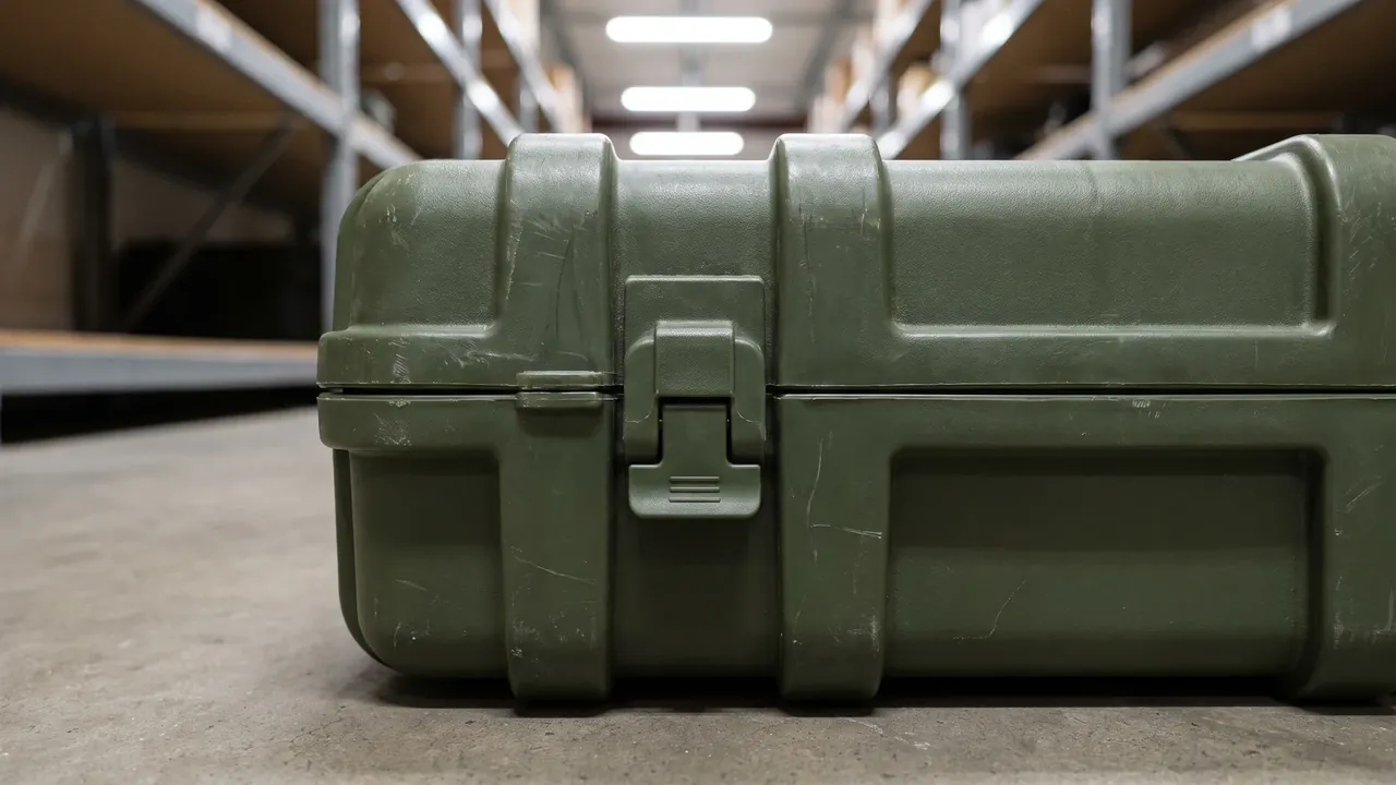
Where a mission includes airdrop, container-side attention focuses further on managing landing impact energy. Airdrop imposes a single, high-energy, essentially vertical event, so cushioning must absorb a large amount of energy within a short stroke. For a modular platform this means reserving mounting interfaces for airdrop cushioning components, or building cushioning into a dedicated airdrop base, rather than trying to satisfy routine transport and airdrop with one liner. Lifting interfaces belong in the same planning: some airdrop and rapid-unload scenarios use slings, so the case needs verified lifting points with stated attitude and allowable load. All of these interfaces should be reserved at platform design stage instead of being improvised when a mission arrives. Load verification logic for tie-down and lifting points appears in the military protective case selection guide.
Fast Access and Human Factors: Latches, Opening, Gloved Use
The final user of a mission-configured system is a person working under pressure, so human factors decide whether the system works at all. Access speed depends on latch type, lid opening method, and liner friction. For latches, over-center catches and lever locks are the steadiest to operate with gloves, while twist locks seal well but take longer. For the lid, gas struts or a limit link hold it at an open angle so the user does not need a hand to keep it up. For liners, cavity entries should be chamfered or ramped so equipment slides in rather than catching.
Gloved operation is an easily neglected test condition. Many designs perform well bare-handed and fail completely with thick gloves, because catches are too small to pinch, zipper pulls too fine to grip, or markings too small to read. Bringing a simulated operation test into human factors design is therefore worthwhile: ask a user to complete a full open, retrieve, and close sequence while wearing gloves in low light, recording time and error points. Module changeover order also affects efficiency. If a frequently used module sits at the bottom, users must move other modules first every time, so the configuration order should be adjusted. Treating access efficiency as a design target rather than a post-hoc assessment is what separates a mission system from an ordinary transit case.
Inspection and Acceptance: Module Integrity and Batch Consistency
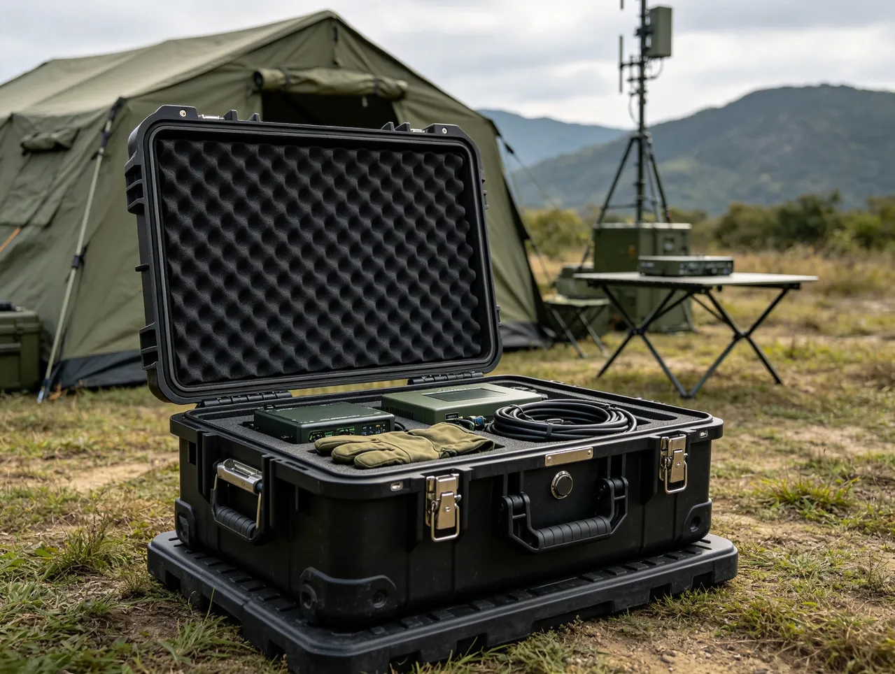
Acceptance for a modular system is more complex than for a single container because platform and modules must both be verified. Platform items include external dimensions, sealing performance, latch and hinge cycling, hardware corrosion resistance and fastener torque, stacking load and tie-down point loads, and interface dimensions and tolerances. Module items include interchangeability with the platform, positioning accuracy, locking reliability, and item-by-item verification of the module list. Interchangeability verification matters most: draw random modules and random platforms from the same batch and cross-assemble them, confirming that any combination seats reliably, rather than validating only a one-to-one demonstration pair.
Batch consistency is the precondition for long service. Platforms and modules are typically procured and replenished in separate batches, and if interface dimensions, compression force, or locking feel drift between them, cross-assembly fails and users memorize which module only fits which case, erasing the modular advantage. The technical document should therefore define key interface tolerances, locking force ranges, liner density and compression set limits, with sampling verification at acceptance. For long programs, wear items such as gaskets, latches, module trays, and straps belong in the spare parts catalog with agreed replenishment intervals. Where a program follows a military standard system, qualification testing should be completed to the customer's designated standard. Domestic requirements are summarized in the GJB military standard case guide.
Common Failure Modes and Procurement Pitfalls
Failure modes in modular systems follow clear patterns. The first is module mismatch, where loose interface tolerances or unclear marking let a user fit a module to an incompatible platform, compression is incomplete, and the module shifts in transit. Unified interface references, poka-yoke features such as asymmetric locating pins, and stronger marking prevent it. The second is quick-change structure failure, where clips release under vibration or slides jam with grit, so the module loses restraint. Secondary locking, dust protection for slides, and combined cycling and vibration testing address it. The third is liner collapse, where module tray foam loses resilience under frequent handling, positioning accuracy falls, and a scheduled tray replacement tied to handling frequency prevents it.
The fourth is localized loss of platform rating, where holes drilled for module mounting or unsealed feed-throughs reduce the whole case's water resistance. Keeping mounting points inside the cavity and using sealed feed-throughs with separately stated requirements prevents it. The fifth is lost module management, where numbers wear off and checklist cards disappear until unidentified items appear in the case. Durable marking, fixed checklist cards, and inclusion in the equipment management system prevent it. Procurement mistakes reduce to four: treating modularity as extra foam rather than an interface system, validating only demonstration pairs without cross-assembly, ignoring the fatigue life and spare supply of quick-change parts, and omitting the module-platform compatibility matrix from the technical document. Settling these four points early sharply reduces rework. Communication module interfaces are discussed in the communication electronics protective case overview and the rotomolded protective case reference.
Closing Perspective: Configuration Moves with the Mission, Protection Stays Constant
What makes a mission-configured case valuable is not that it is tougher than an ordinary transit case, but that it brings change into the design. The platform layer stays constant so that habits around opening, securing, and carrying settle into stable muscle memory. The module layer moves with the mission so the same containers serve different inventories. Interfaces and marking connect the two, turning changeover into a defined action rather than improvisation. Achieving this requires working through size families, interface tolerances, quick-change forms, marking systems, and spare parts planning item by item, because a missing link turns modularity into nothing more than a lot of boxes. For buyers, sharing the real mission profiles, changeover frequency, environmental conditions, and maintenance resources with the supplier lets the system be designed around the rhythm of use rather than around a tidy drawing. Where defense-related equipment is transported or delivered, the earlier point stands: local regulations and export control requirements govern, and this article discusses packaging containers only.
Frequently Asked Questions
Q: What exactly does mission-configured modular layout mean for a special forces case? A: It describes a design approach that splits the container into a platform layer and a module layer, not a case with extra foam blocks. The platform layer includes the shell, lid, latches, sealing structure, stacking faces, and tie-down points, all of which stay constant across missions so that operating habits remain stable. The module layer includes liner boards, trays, soft packs, and accessory fixtures, which change with the packing list so users only adapt to a new internal arrangement. The benefit is that one fleet of containers serves different inventories, cutting equipment variety and inventory pressure while keeping operating habits consistent, which lowers training cost and operating risk. Making this work requires unified interfaces, including mounting reference planes, locating pin positions, fastening methods, and compression travel, all with stated tolerances in the technical document. Modularity without interface discipline degrades into many mutually incompatible cases that users must memorize, which increases rather than reduces field burden.
Q: Should modules be divided by mission, by user, or by function chain? A: Each dimension has its own emphasis, and practice usually blends all three. Dividing by mission profile groups common missions and defines a module set for each, such as short reconnaissance or extended field stay. Changeover is fast because a user takes the set matching a mission code, but module variety grows and inventory management gets more complex. Dividing by user assigns modules per individual or team, which supports distribution and accountability but demands high standardization or modules from different people will not combine. Dividing by function chain groups equipment into communication, medical, tools, and power, which is the most universal approach since any mission can be assembled from function modules, though it asks more judgment of users and therefore more training. A practical blend defines base modules by function chain and then creates predefined combination packs for high-frequency missions, moving the judgment burden from users to the logistics system. A useful test is to count how many modules must move during a changeover and how long each move takes.
Q: Does quick-change liner structure sacrifice protection reliability? A: It involves a tradeoff, but graded design keeps the impact manageable. Magnetic or clip-on locating boards change fastest and suit light modules, though they can release under vibration and need secondary locking. Slide rails with locking buttons are fast and carry medium loads well, at the cost of space and a need for dust protection, since grit jams them. Fasteners with quick-release handles are the most reliable and best at resisting vibration, but relatively the slowest to change. The pragmatic approach grades by module weight and use frequency: clips with quick straps for frequent light modules, quick-release fasteners for infrequent heavy ones, so speed and reliability each get their due. All quick-change parts should also enter a life assessment combining open-close cycling with vibration, confirming they survive the rated number of cycles, with a stated replacement interval and spare supply. With sensible grading and controlled life, quick-change structure does not meaningfully weaken overall protection.
Q: How should the sealing and protection rating of the platform be determined? A: It is best fixed as a common platform baseline, set from the harshest environment rather than the average or a single mission, because a common platform cannot be downgraded for one job and users need a stable expectation. Typical baseline items include dust and water rating, operating temperature range, UV resistance, and corrosion resistance. Sealing reliability depends on three elements working together: gasket material and compression, lid stiffness and even compression, and latch spacing and travel. Modular systems carry one extra caution, since a module must not break platform sealing. Some designs drill through the shell to mount modules, and without sealing provision the entire case rating becomes a function of that hole. The safer approach keeps mounting points inside the cavity and avoids wall penetration. Where a penetration is genuinely required, use a sealed feed-through and state its protection requirement separately in the technical document so acceptance testing covers it.
Q: How is isolation handled when the same case carries loads of very different weight? A: Zoned isolation is the answer, rather than one set of parameters stretched across all loads. Isolation is normally sized for a typical load, so a load well below design value feels too soft and contents shift inside, while a load well above it consumes the stroke and transmits shock directly. Zoned isolation divides the cavity by module and gives each zone independent cushioning characteristics: heavier zones use higher stiffness and a shorter stroke, lighter zones use lower stiffness and a longer stroke, and the frame between zones handles load transfer so zones do not interfere. Retention follows the same logic, with hard stops and straps for heavy modules forming a rigid unit, and molded foam or elastic plates for light modules balancing positioning and access. With mixed loads, clearances between adjacent modules and differences in stiffness also matter, and a cushioning separator or independent restraint may be needed, with load sharing across modules included in verification rather than analyzing each in isolation.
Q: What different requirements do air transport and airdrop place on the container? A: The emphases differ. Air transport concentrates on three points. Pressure differential comes first, since a well-sealed case becomes hard to open as altitude rises and the gasket takes extra stress, so a pressure-equalization valve is required. Restraint comes second, since cabins require containers secured by tie-down straps, so the shell needs defined tie-down points rated against inertial rather than static loads. Stacking and geometry come third, because cabin loading favors regular stackable shapes, which points to rectangular profiles and stacking bosses. Airdrop focuses further on landing impact energy management, a single high-energy essentially vertical event that requires absorbing a large amount of energy within a short stroke. For a modular platform, this means reserving mounting interfaces for airdrop cushioning components or building cushioning into a dedicated airdrop base, rather than asking one liner to satisfy both routine transport and airdrop conditions. Lifting interfaces should be reserved in the same planning stage.
Q: What marking and traceability measures does modular management require on the container side? A: The system must answer three questions: which module this is, which mission combination it belongs to, and when it was last inspected. The engineering approach assigns a unique number to every module, with the mapping between numbers and mission combinations held in a configuration table. Color and graphics on the exterior distinguish function classes, using color for fast sorting and graphics for accurate identification. A checklist card fixed to the module lists required items, quantities, and inspection dates, which lets users verify before and after every use. Durability matters as much as design, since paper labels fail quickly in damp, oily, and abrasive conditions, so molded-in graphics, screen printing with a protective overcoat, or solvent-resistant engineering-plastic nameplates are preferable. Low-light service calls for retroreflective material at key markings. On the management side, modules belong in the unit's equipment system with common asset numbers and inspection records, plus a compatibility matrix stating which modules fit which platforms.
Q: How does acceptance of a mission-configured case differ from that of an ordinary protective case? A: It differs in verifying platform and modules together and in adding interchangeability validation. Platform items include external dimensions, sealing performance, latch and hinge cycling, hardware corrosion resistance and fastener torque, stacking load and tie-down point loads, and interface dimensions and tolerances. Module items include interchangeability with the platform, positioning accuracy, locking reliability, and item-by-item verification of the module list. Interchangeability validation is the critical addition: draw random modules and platforms from the same batch and cross-assemble them, confirming any combination seats reliably, rather than validating a single demonstration pair. Batch consistency is the precondition for long service, because platforms and modules are procured in separate batches; if interface dimensions, compression force, or locking feel drift, cross-assembly fails and users memorize which module fits which case, which erases the modular advantage. Key interface tolerances, locking force ranges, and liner compression set limits should therefore be fixed in the technical document and sampled at acceptance.
Q: What are the most common procurement mistakes for mission-configured cases? A: Four stand out. The first is interpreting modularity as extra foam blocks rather than an interface system, so modules are not interchangeable and management cost rises instead of falling. The second is validating only demonstration pairs without cross-assembly testing, which looks fine at acceptance until later batches reveal that accumulated tolerances prevent modules from seating. The third is ignoring the fatigue life and spare supply of quick-change parts, so clips, slides, and locking buttons fail after repeated use, the case loses restraint, and no replacements exist in the field. The fourth is omitting the module-platform compatibility matrix from the technical document, leaving users to combine items from memory and creating the familiar situation of having modules that fit no available case. Avoidance is straightforward: write interface dimensions and tolerances, compression force ranges, quick-change part life targets, interchangeability validation methods, the spare parts catalog, and the compatibility matrix into the technical requirements and acceptance plan, so the supplier completes verification before delivery rather than leaving problems for the field.