

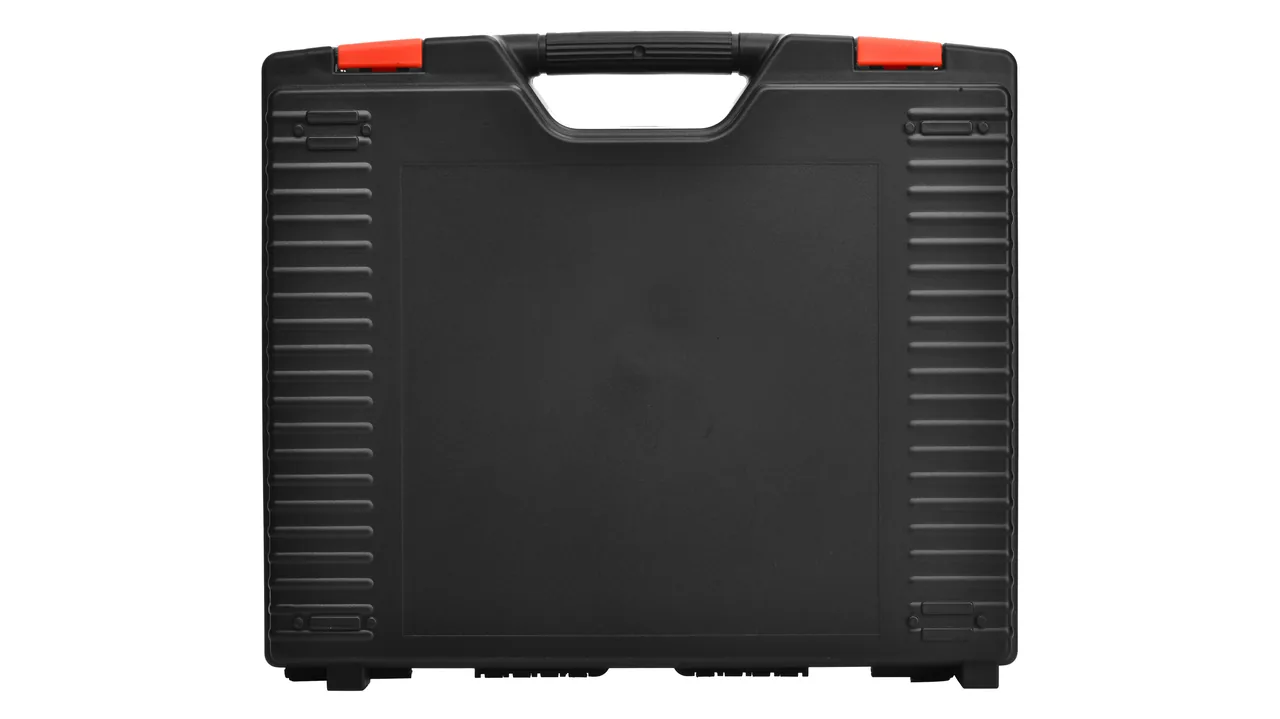
Components from a steel pickling line are the hardest items in a metallurgical plant to pack cleanly. The rubber cover on a squeeze roll is built to press acid out of strip under tens of tonnes of roll force, not to carry a stack. A pickling nozzle has a ceramic core only a few millimetres thick, and its orifice accuracy sets how evenly the acid is distributed, so one drop can shatter it. A pump mechanical seal pairs silicon carbide against carbon graphite, and both are hard and brittle, so a single chipped corner means it will never seal again. These parts also leave the line carrying a memory of hydrochloric acid fog, with chloride trapped in lining gaps, thread roots and O-ring grooves, still attacking every metal item inside a closed case.
The protection logic for pickling line parts is not "wrap them in acid-resistant material" but "remove residual acid as an internal source first, then set the load path and isolation boundary for each part." Rubber roll faces must not be compressed, ceramic parts must not take impact or cantilever bending, seal friction pairs must not touch anything hard, and chloride residue must be neutralised before the case is closed. JUNZHIJIA sorts pickling line parts first by residual acid risk and second by load path, then fixes cleaning, support, isolation and moisture control item by item.
Table of Contents
- Compression Set and Ageing Control for Squeeze Roll Rubber Covers
- Ceramic Nozzle Core Fracture and Orifice Diameter Retention
- Seal Face and O-Ring Interface Protection for Acid Pumps
- Corrosion Boundaries of Hydrochloric Acid Fog on Case Hardware
- Preventing Delamination at Chrome Plate and Rubber Bond Lines
- Edge Protection for Acid Tank Lining Sheets and Welds
- Chamber Separation Between Rinse Zone and Dryer Zone Parts
- Brittle Part Protection for Graphite Heat Exchangers and Acid Lines
- Indexed Numbering and Batch Traceability for Nozzles and Seals
- Rust and Impact Protection for Squeeze Roll Journals and Couplings
- Anti-Crush Stacking and Load Path Design for Pickling Line Parts
- Arrival Inspection and Residual Acid Tracing for Squeeze Rolls and Nozzles
- Frequently Asked Questions FAQ
- Conclusion and Related Reading
Compression Set and Ageing Control for Squeeze Roll Rubber Covers
A squeeze roll, also called a wringer roll, is a steel core with a rubber cover, usually EPDM, chloroprene or chlorosulfonated polyethylene, at Shore A 50 to 70 with a cover 10 to 30 mm thick. It presses against the strip under roll force and squeezes off residual liquor, so the cover's resilience and surface flatness are the whole value of the part.
| Failure mode | Trigger | Packing measure |
|---|---|---|
| --- | --- | --- |
| Permanent indentation, compression set | Roll face used as a stacking load face, or long storage in one posture | Support at the journals, cover in free air, never stack roll on roll |
| Cracking and hardening | Long exposure to ozone, ultraviolet or oil mist | Wrap the whole roll in PE or aluminium composite film, keep away from solvents |
| Cover delamination | Shear at the bond line, or solvent ingress | No tape on the roll face, no solvent wiping of the bond area |
| Surface scoring | Rubbing against hard parts or dust | Lint-free soft liner, no fasteners in the same pocket |
Indentation is the most common and most irreversible transit defect. Rubber compression set develops markedly once compression exceeds 15 percent for several days, and after unloading the face cannot recover its roundness, leaving a local flat that wrings unevenly and raises the rinse load afterwards.
The correct arrangement is journals carry the load, cover stays in free air. Use two V-saddle sets at the journals with spacing as close to the roll ends as possible without touching the cover, and leave 10 to 20 mm between cover and liner. Where layers are unavoidable, use rigid shelves and rotate the support positions of adjacent rolls by 90 degrees.
Ozone protection deserves emphasis. Ozone, the leading cause of rubber cracking, comes from welders, variable frequency drives, high-voltage motors and UV lamps, all dense in a pickling shop, so long storage there carries a far higher cracking risk than a general workshop. Wrap the roll in PE or aluminium composite film, which blocks ozone and UV while keeping acid fog out. Comparable compatibility logic appears in corrosion-resistant enclosure material selection limits.
Ceramic Nozzle Core Fracture and Orifice Diameter Retention
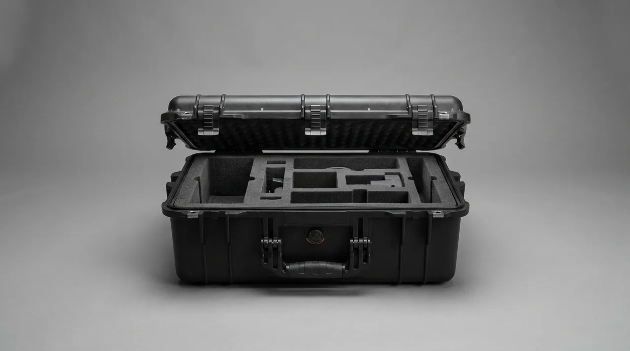
Pickling nozzles sit in the acid spray, rinse and final wash zones, made from silicon carbide, alumina ceramic, or engineering plastic with a ceramic insert. Orifice diameters typically run from 1 to 6 mm, and the orifice geometry, whether flat fan, hollow cone or full cone, sets the uniformity of acid coverage.
Ceramic core fracture comes first, because ceramic fracture toughness is very low, with silicon carbide at about 3 to 4 MPa·m<sup>1/2</sup>, and the wall at the orifice may be only 1 to 2 mm thick, so a point impact shatters it; give each nozzle its own pocket, wrap the body rather than the orifice, and keep orifices facing the same way with nothing hard in contact. Orifice wear enlargement follows: wear depends strongly on solids content and flow velocity, and an in-service nozzle may already be 10 to 30 percent oversize with a bell-mouthed edge, so transit adds no wear but dust entering the orifice does create fresh abrasive particles; plug the orifice after cleaning and bag each nozzle. Thread damage is third, because the connection thread, commonly G1/4, G3/8 or NPT, is the installation face and a knock deforms it into a leak; cap the thread and keep nozzles out of pockets holding metal parts.
Orifice orientation is the detail most often missed. Laying a nozzle on its side puts the orifice against the neighbouring divider, whereas the right posture is orifice facing up with the body outside diameter locating the part, on an annular rather than flat pocket floor.
Cleaning follows. In service both inside and outside carry acid and iron salts, so rinse with water, neutralise with one to two percent sodium carbonate solution, then rinse with deionised water and dry. Skip neutralising and residual acid evaporates inside the bag and re-condenses, creating a locally concentrated acid environment that pits the body, especially metal inserts. Grading ceramic parts follows the same approach used on plating lines, described in electroplating line part protection.
Seal Face and O-Ring Interface Protection for Acid Pumps
Acid pumps are usually fluoroplastic-lined centrifugal or magnetic drive machines, and the mechanical seal is the most fragile assembly. A common arrangement is a double mechanical seal with silicon carbide against carbon graphite, or silicon carbide against silicon carbide, with FKM, FFKM or PTFE-encapsulated O-rings as secondary seals.
Seal face chipping matters first, because both silicon carbide and carbon graphite are brittle and face runout is usually held within 0.02 mm, so a chip of even 0.1 mm prevents a complete fluid film and guarantees a leak at start-up. O-ring compression set is second: an O-ring left compressed, for instance when the seal is packed without releasing the spring preload, takes a permanent set along the compression axis, and FKM shows measurable set after a few hundred hours at 25 percent compression and 70 degrees Celsius. Spring and drive pin deformation is third, since the compensating spring collapses or shifts under shock and the drive pin bends, leaving face contact pressure uneven.
| Component | Packing method | Prohibited |
|---|---|---|
| --- | --- | --- |
| Seal rings, silicon carbide or carbon | Own pocket, face up, annular soft support | Two seal rings stored face to face |
| O-rings | Individual PE bag, no stretching, laid flat | Hung on hooks or left compressed |
| Springs and drive pins | Own small pocket with a number | Mixed with metal parts |
| Complete seal assembly | Preload released and fixed, face guard fitted | Shipped in the service preload state |
The complete seal assembly is what gets neglected. To save effort, crews pull a mechanical seal cartridge and pack it exactly as removed, spring still compressed. Weeks later the set has formed, and after installation the face contact pressure is too low. Release the spring preload as the manual requires, or fit the maker's transport stop, and cap the seal faces.
Corrosion Boundaries of Hydrochloric Acid Fog on Case Hardware
The characteristic medium on a pickling line is hydrochloric acid at 5 to 20 percent concentration and 60 to 90 degrees Celsius, so acid fog is permanently present in the shop air. Once it enters a case with the parts and condenses, it creates an extremely aggressive micro-environment.
| Material | Behaviour in chloride environment | Packing recommendation |
|---|---|---|
| --- | --- | --- |
| Carbon steel, cast iron | Significant corrosion rate, visible rust above 60 percent RH | VCI plus desiccant mandatory, never bare |
| Zinc plating | Chloride destroys the coating quickly, white corrosion products | Avoid galvanised fasteners inside the case |
| 304 stainless | Chloride breaks the passive film, pitting and crevice attack | Not suitable for long exposure to residual acid |
| 316L stainless | Better pitting resistance, but crevices still corrode | Acceptable for case hardware if crevices are avoided |
| Aluminium | Hydrochloric acid dissolves the oxide film rapidly | Never as a load-bearing liner frame against acid parts |
| PP, PVDF, PTFE | Good resistance to hydrochloric acid | Preferred for liners and dividers |
The table has a direct consequence: metal fasteners, hinges and tie rods inside the case must be reselected on corrosion grounds.
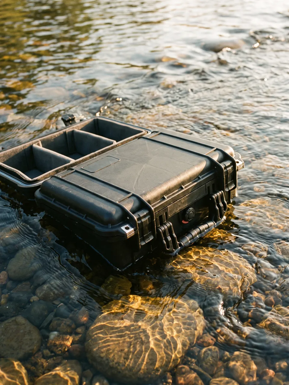
Humidity is the second boundary. Hydrochloric acid corrosion accelerates markedly above 60 percent relative humidity, because a water film is needed as the electrolyte. Fit desiccant at about 20 g per cubic metre of free volume with a humidity indicator card at 40, 50 and 60 percent thresholds, and keep the case sealed to at least IP65 as defined by IEC 60529 and GB/T 4208. On sea freight or humid routes, increase desiccant by half and fit a pressure equalisation valve so temperature swings do not load the seal repeatedly.
Desiccant lowers humidity, it does not neutralise acid. If parts go into the case carrying residual acid, the moisture the desiccant absorbs forms an acidic solution and creates local concentrated acid spots. The order of operations must therefore be neutralise, dry, rust-proof, then moisture-proof. Trade-offs for packing materials in chemical media appear in chemical reactor part packing boundaries and metal rolling mill part protection and rust prevention.
Preventing Delamination at Chrome Plate and Rubber Bond Lines
A pickling line also uses hard-chrome plated rolls such as tension, steering and deflector rolls, with plating 20 to 100 micrometres thick and hardness HV 800 to 1000. The purpose is wear and corrosion resistance, and the bond to the steel substrate is part mechanical interlock and part metallurgical, so shear strength is far below what the coating hardness suggests.
Flaking starts at the roll end chamfer or edge, where the plate is thinnest and stress is most concentrated; a knock in transit or the peel force of removing an adhesive creates edge shear, and once the bond opens, acid and moisture enter, corrosion products jack the plate up and the area grows. Craze cracking forms a fine network after repeated loading, and acid penetrates the cracks to the substrate, which then corrodes and lifts the plate further. Edge chipping occurs where the end chamfer plate is thinnest.
Packing requirements overlap with those for rubber rolls: journals carry the load and the roll face stays in free air. The difference is that chrome rolls do not need ozone protection but do need scoring and shear protection. The face must touch no hard part, the liner should be lint-free soft material, and the roll ends need soft boots over the chamfers. Never apply tape or labels directly to the roll face or roll end, because the peel force on removal shears the plate edge and is a common trigger for flaking.
For a roll already showing crazing, assess before shipping with a magnifier, judging crack density and depth. Where crazing is shallow and limited the roll may continue in service if the location is recorded; where cracks reach the substrate, arrange re-plating before shipping, because transit vibration drives corrosion products deeper under the plate.
Rubber bond line delamination is prevented in the same spirit: apply no shear to the bond area, do not wipe it with solvent, and do not let it sit in oil. Locate on the journals so the cover takes no clamping force. Where the cover has already lifted, mark it and repair before shipping, because vibration enlarges the separated area and the arriving part usually needs a full recover.
Edge Protection for Acid Tank Lining Sheets and Welds
Pickling tank linings fall into three families: rubber lining, usually natural or butyl rubber at 3 to 6 mm, plastic sheet lining in PP, PVC or PVDF at 3 to 10 mm, and glass flake or glass-reinforced lining. Lining failure almost always begins at edges, welds and corners, because these locations concentrate stress and also trap medium. If a lining sheet edge is squeezed or lifted in transit, the location becomes the path for acid penetration after installation: acid migrates between lining and steel shell, causing crevice corrosion that finally lifts the whole lining away. Such damage is usually invisible during transport and only appears weeks after reinstallation.
Four measures apply. Protect the edges by wrapping every cut edge and weld edge with soft edging strip at least 5 mm thick, in EVA or sponge. Never stack lining sheets, because the upper weight concentrates on the edges, producing impressions and lifted edges; where stacking is unavoidable, use equal-height blocks so the load lands on the flat area. Support the sheets face down with points at least 100 mm from any edge, and never directly under a weld. Clean and neutralise the surface afterwards and wrap it in PE or aluminium composite film so residual acid cannot keep working on it.
Welds need separate treatment. Rubber lining lap seams and plastic sheet weld seams are commonly 20 to 40 mm wide, and a hard object pressing on one deforms it locally and opens a micro-gap. Bridge each weld with a soft protection strip of the same width, fixed to the adjacent flat area rather than to the weld itself.
Observe the order of cleaning. Rinse with water first to remove acid and iron salt scale, neutralise with one to two percent sodium carbonate, then rinse with deionised water and blow dry. Never use a wire brush or hard scraper on the scale, because scratches become anchor points for the next scale layer.
Chamber Separation Between Rinse Zone and Dryer Zone Parts
Rinse zone parts, including rinse nozzles, spray headers, water dams and wringer rolls, contact dilute acid and clean water, so residual acid risk is low but humidity risk is high, and most are stainless, which makes chloride pitting the main threat. Dryer zone parts, including hot air circulation blowers, heaters, air knives, conveyor rolls and insulation panels, see hot humid air, so residual acid risk is lowest but rust risk is high, because humid air near the dryer condenses on cooler parts, and blower impellers and heating elements are precision or brittle items.
| Chamber | Contents | Isolation requirement |
|---|---|---|
| --- | --- | --- |
| Acid chamber | Acid nozzles, acid pump parts, lining sheets | Neutralised and dried, individually sealed, physically separated |
| Rinse chamber | Rinse nozzles, spray headers | Dehumidification first, desiccant and humidity card |
| Dryer chamber | Blower impellers, heating elements, air knives | Rust prevention first, brittle parts in their own pockets |
| Precision chamber | Mechanical seals, sensors, instruments | ESD, moisture and individual pocket control |
Cross-chamber mixing is a two-way risk. Acid zone parts carry acid fog into the dryer chamber and corrode blower impellers and heating elements, while heating elements sharing a chamber with acid parts have their terminals corroded faster by the residue. Where parts must share one case, place a sealed partition wall with its own gasket between chambers rather than relying on a layer of foam.
Brittle Part Protection for Graphite Heat Exchangers and Acid Lines
Acid heating systems widely use impervious graphite heat exchangers in block, shell-and-tube or plate form. Their mechanical behaviour is that of a brittle material: compressive strength of 30 to 70 MPa but flexural strength of only 15 to 30 MPa, with poor impact resistance and extreme sensitivity to local load and cantilever bending.
Three requirements follow. No cantilever loading is allowed: if a module is supported at one end with the other free, its own weight creates bending in the graphite block, and added transit vibration causes cracking directly. Provide full base support or support at both ends, with soft material such as EVA or rubber pad over the whole contact face, never point or line support. No fastener may clamp the graphite body directly: clamping should pass through a steel pressure plate with an elastic washer, torque must be controlled to the maker's figure, and if the service clamping state is retained, fit transport stops to limit movement. Connections must be capped and protected: acid inlet and outlet are usually flanged or threaded, and a knocked flange face cannot be sealed or repaired on site, so fit flange covers, thread plugs and a soft collar.
Acid piping in PP, PVDF, PTFE-lined steel or GRP mainly risks bending and end damage. Long pipes need multiple supports with spacing calculated from section inertia, in practice no more than 1.5 to 2.0 m, with overhang never beyond 300 mm. Never subject lined pipe to impact at low temperature, because fluoroplastic linings become brittle when cold.
Brittle graphite and ceramic parts share one methodology: spread the load across a face, avoid every point contact, avoid every cantilever, and limit acceleration. The same approach is discussed systematically for another brittle carbon product in heat exchanger parts and brittle product packing.
Indexed Numbering and Batch Traceability for Nozzles and Seals
A major pickling line overhaul releases an astonishing number of small parts: nozzles may number in the hundreds, O-rings come in dozens of sizes, and bolts and shims run into the thousands. Two properties make them difficult: appearance differences are minute, and correct location matters a great deal.
Nozzle numbering is especially valuable. Nozzles at different positions on one spray header may differ in flow rate and spray angle, for example a 65 degree and an 80 degree flat fan, and fitting the wrong one changes acid coverage directly, showing up as uneven pickling between strip edge and centre. O-ring specifications are even more deceptive: two rings with the same outside diameter but line thickness differing by 0.5 mm are almost indistinguishable by eye, yet fitting the wrong one guarantees a leak.
Four practices make it work. Number pockets to match equipment tags, such as P1-03 for nozzle three on spray header one, rather than simple sequence numbers. Use colour codes for quick visual checks plus text marking of specification, meaning orifice diameter, spray angle and material, for final confirmation. Fill unused pockets with contrast-coloured plugs. Attach a pocket list inside the lid and record the batch number and production date of every seal, so compression set can be checked batch by batch on arrival. Rubber performance degrades with time and storage conditions, and the recommended storage life for FKM and FFKM is typically five to ten years from production given suitable conditions.
Rust and Impact Protection for Squeeze Roll Journals and Couplings
A journal typically includes a ground bearing seat at h6 or k6 tolerance, a keyway and a coupling fit. In service these faces are protected by oil lubrication and seals, so rust risk is low; once exposed to pickling shop air after removal, chloride and moisture form pits on the ground surface quickly, and those pits become local high points during assembly, producing abnormal bearing clearance or making coupling alignment difficult.
Handle only with gloves on cleaned machined faces, since sweat chloride is especially damaging to stainless. Wrap journals and bearing seats in VCI film, keeping it within about 30 mm of the metal surface because VCI only works at short range, then bag in PE. Fill keyways with soft filler before wrapping so the edges cannot be rolled over, and coat coupling teeth, where present, with a thin rust-preventive grease under a guard. Never use the journal end face as a support point or let it bear on the case wall; leave at least 20 mm of clearance at the shaft end with a soft end cap.
Where rust spots have already formed, measure before repairing. Dress with a fine oilstone circumferentially, then take micrometer readings in two perpendicular directions at the same cross-section and confirm cylindricity before assembly. If pit depth exceeds 0.02 mm, or if pitting sits where a bearing race makes contact, replace the part or fit a sleeve. Do not hand-sand with abrasive paper, because the grains embed in the softer metal and become a new source of wear particles. Similar treatment appears in refinery pump part protection and seal care and salt spray corrosion testing for packing class selection.
Anti-Crush Stacking and Load Path Design for Pickling Line Parts
Pickling line parts are generally long and heavy. A squeeze roll may be 1.5 to 2.5 m long and weigh 200 to 800 kg, and lining sheets or heat exchanger modules can exceed 500 kg each.
Three rules govern the load path. Loads pass through the steel structure, never through functional faces: roll loads travel from journal to saddle to case floor beam, exchanger loads from base to pad to pallet, and functional faces such as roll cover, graphite block and flange face should see only small distributed loads. Support count and spacing follow a stiffness calculation: slender rolls behave as simply supported beams with spacing of no more than a third of roll length, while long pipes and profiles should be spaced so mid-span deflection stays within L/1000. Dynamic amplification must be included: road transport vertical acceleration peaks commonly reach 1.5 to 2.5 g, rail and sea freight higher, so stacking layer counts and load-bearing components normally take a safety factor of 1.8 to 2.5.
| Part type | Typical unit weight | Support method | Stacking limit |
|---|---|---|---|
| --- | --- | --- | --- |
| Squeeze roll with rubber cover | 200 to 800 kg | V-saddles at journals, cover in free air | No roll-on-roll stacking, rigid shelves required |
| Chrome plated and deflector rolls | 100 to 500 kg | Saddles at journals, face in free air | As above, no tape on the face |
| Acid tank lining sheet | 50 to 300 kg | Face support, points 100 mm or more from edges | No edge-loaded stacking |
| Graphite exchanger module | 100 to 500 kg | Full-area soft pad support | Single layer, nothing stacked above |
| Acid pump and pump set | 100 to 400 kg | Base support, discharge pipe independently supported | 2 to 3 layers, heavy items low |
| Spray headers and piping | 20 to 150 kg each | Multiple supports at 2 m maximum spacing | Vertical rack or layered, no cantilever |
Centre of gravity and lifting points matter too. A roll's centre of gravity sits at mid-length, so lifting points should be symmetrical about it and the case exterior must mark the centre and the lifting points. Exchanger module centres of gravity often sit towards one end, so lift with four points and a spreader beam. The no-cantilever rule holds for every brittle and long part, and it is the single most important line in pickling line packing design.
Arrival Inspection and Residual Acid Tracing for Squeeze Rolls and Nozzles
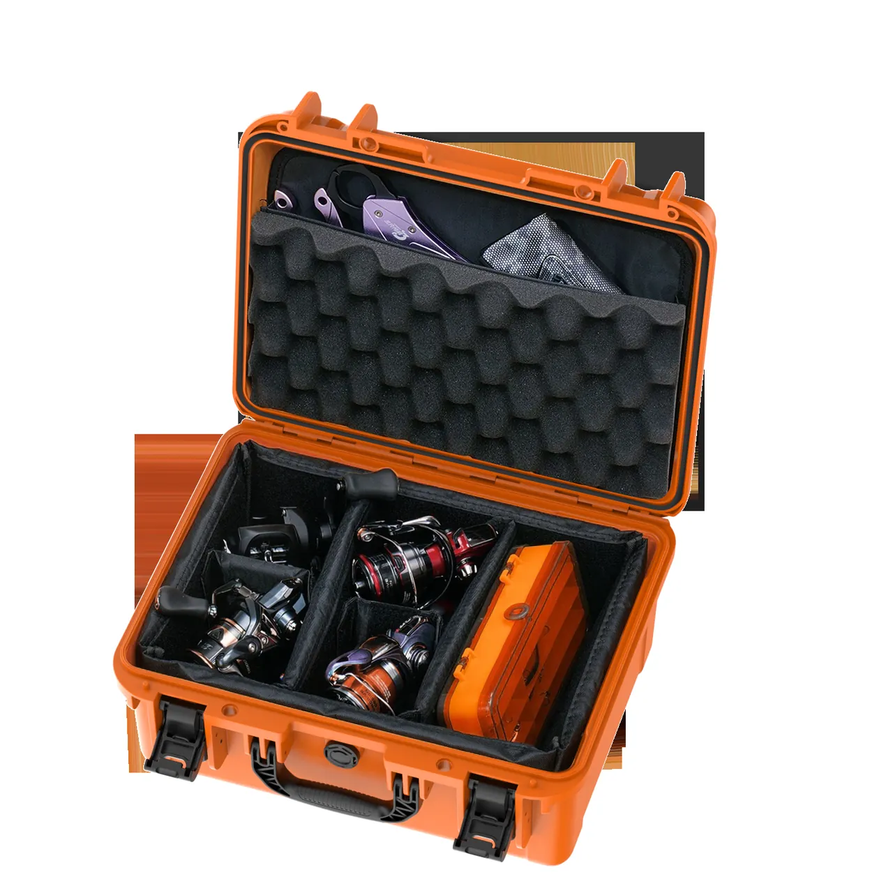
Arrival inspection on a pickling line has a step other lines do not need: deciding whether the parts have picked up residual acid, because residual acid may come from the parts themselves or from cross-contamination during packing or transport.
Stage one covers packing and appearance. Check the case, seal, humidity indicator card and VCI film, then press deionised-water-dampened pH paper against the inner liner to check the chamber; a reading below 5.5 indicates an acid source inside.
Stage two covers residual acid tracing and cleaning confirmation. Apply three tests to suspect parts: pH paper contact, expecting 6.5 to 7.5; chloride detection with silver nitrate paper or titration, which gives qualitative evidence of chloride residue; and conductivity of a deionised water rinse, normally required below 10 microsiemens per centimetre. A failure in any test requires re-neutralising and re-cleaning.
Stage three covers dimensions and function.
| Part | Check item | Acceptance criterion |
|---|---|---|
| --- | --- | --- |
| Squeeze roll | Cover hardness, roundness, surface | Hardness within tolerance, roundness 0.3 mm or better, no indentation or cracking |
| Chrome roll | Plating integrity, roughness | No flaking or cracking to substrate, Ra within drawing limits |
| Nozzle | Orifice, spray pattern, thread | Orifice wear 10 percent or less, spray angle within tolerance, thread passes gauge |
| Mechanical seal | Face flatness, O-ring hardness | Flatness passes, no chipping, O-ring hardness change 5 Shore A or less |
| Graphite exchanger | Appearance, pressure test | No cracks, pressure test passes at specified pressure |
| Lining sheet | Edges, welds | No lifted edges or blisters, welds not separated |
A packing record should carry case number, packing date, packer, part list, cleaning method with pH and chloride results, desiccant and indicator card batches, seal batch numbers, transport mode and duration, and arrival test data. Where corrosion appears, that record is the only way to separate incoming acid, packing error and transport environment.
Frequently Asked Questions FAQ
Q: Why does the squeeze roll rubber cover fear compression, and how much is allowed?
A: Rubber elasticity depends on molecular chains returning to their original arrangement, and once the material sits at a higher compressive strain for long enough, chains slip and rearrange so recovery is incomplete. This is compression set. Field experience suggests losses are usually acceptable within 15 percent compression over a few weeks, while above 15 percent for several days the set develops noticeably and the roll face shows a local flat. Squeeze roll covers are commonly EPDM at Shore A 50 to 70, which is not soft, but the face is designed for line contact against strip under brief compression, not for long-term face loading, so using the face as a stacking load surface is the classic error. Let the journals carry all the weight and leave the cover in free air; where layers are unavoidable, add rigid shelves with equal-height blocks and rotate the support positions of adjacent rolls by 90 degrees so no single generatrix stays loaded. On arrival, measure roundness and inspect for flats, since an out-of-tolerance roll produces uneven residual liquor along the strip.
Q: Can a broken ceramic nozzle core be replaced on site?
A: It depends on the construction. With a separate insert type, where the ceramic core is a distinct part inside a body, replacement is practical, but the orifice diameter and spray pattern must be reconfirmed afterwards, because concentricity of the insert to the body and the orientation of the orifice affect spray angle and coverage width. Use the maker's pressing tool and verify with a go/no-go gauge for orifice diameter and a spray angle template. With a one-piece ceramic nozzle, a broken orifice cannot be repaired and the whole nozzle must be replaced, since ceramic cannot be welded and adhesives fail quickly in acid at temperature. In both cases two further points apply. Collect and remove every fragment, because pieces left inside a spray header will block other nozzle orifices during operation. After replacement, run a flow uniformity check along that header, either by measuring flow per nozzle or by visually checking the spray pattern, so that a single deviating orifice cannot leave a zone under-pickled.
Q: How should an acid pump mechanical seal be protected in transit?
A: Release the preload, protect the faces and isolate the parts. The seal spring is compressed in service to provide face contact pressure, and shipping it that way for weeks causes stress relaxation in the spring and compression set in the O-rings, so contact pressure is insufficient on arrival and the seal weeps. Release the spring as the manual requires, or fit the maker's transport stop. The faces pair silicon carbide against carbon graphite or silicon carbide against silicon carbide, both hard and brittle, with runout commonly held within 0.02 mm, so any hard contact can chip them: fit face guards and never store two seal rings face to face, but in separate pockets, face up, on annular soft support. Bag O-rings individually without stretching, away from light, heat and oil, at 15 to 25 degrees Celsius. Pack the complete cartridge separately from the pump body so pump weight never passes through the seal. On arrival, measure face flatness and O-ring hardness, and replace the O-rings if hardness has shifted by more than 5 Shore A.
Q: How fast does hydrochloric acid fog corrode case hardware?
A: It depends on humidity, temperature and chloride concentration, and humidity is decisive. Below about 40 percent relative humidity, residual hydrochloric acid causes essentially no electrochemical corrosion and steel parts can be stored for long periods. Above 60 percent relative humidity a continuous water film forms, chloride dissolves into it as a strong electrolyte, and the carbon steel corrosion rate rises sharply, with visible rust within days and measurable thinning within weeks. Temperature roughly doubles the rate for every 10 degrees Celsius rise, which is why summer transport carries far higher risk than winter. Type 304 stainless additionally suffers pitting in chloride environments, where attack starts at a local break in the passive film and grows downwards as a deep pit, so the appearance is small holes rather than uniform rust and early detection by eye is difficult; prefer 316L or engineering plastic for case hardware on a pickling line. Two controls matter, removing residual acid at source by neutralising to neutral, and holding case humidity below 60 percent with a sealed shell, since desiccant cannot neutralise acid.
Q: Why do chrome plating and rubber bonding layers delaminate?
A: The mechanisms differ but both involve interfacial shear. Chrome plate usually lifts from the roll end chamfer or edge, where the coating is thinnest and stress is most concentrated; a knock in transit or the peel force of removing an adhesive creates edge shear, and once the bond opens, acid and moisture enter, corrosion products jack the plate up and the flaked area grows. Rubber cover delamination is more often caused by solvents, oils and ozone: mineral oil swells rubber, chlorinated solvents such as trichloroethylene destroy the bond between rubber and steel core, and ozone cracks the surface and spreads along the interface. Packing therefore follows three rules: never apply tape or labels to a roll face or roll end, never wipe with mineral oil or chlorinated solvent, never leave the bond area sitting in oil, and wrap the whole roll in film to block ozone and ultraviolet. On arrival, arrange re-plating or recovering before installation if crazing has reached the substrate or if the rubber bond has lifted, because vibration lets those defects grow in transit.
Q: How should the edges and welds of acid tank lining sheets be protected?
A: Lining failure almost always starts at edges, welds and corners, so protection comes down to three prohibitions: no squeezing, no edge-loaded stacking and no trapped medium. Wrap every cut edge and weld edge with soft edging strip at least 5 mm thick, in EVA or sponge. Do not stack lining sheets, because the upper weight concentrates on the edges and creates impressions and lifted edges; where stacking is unavoidable, use equal-height blocks so the load lands on the flat area. Place support points at least 100 mm from any edge and never directly under a weld, so the weld never becomes a load point. Bridge each weld with a soft strip of the same width, fixed to the adjacent flat area rather than to the weld itself, so removing the strip cannot pull the seam. For cleaning, rinse with water to remove acid and iron salt scale, neutralise with one to two percent sodium carbonate, rinse with deionised water and blow dry. Never use a wire brush or hard scraper, because scratches become anchor points for the next scale layer.
Q: How do you tell whether pickling line parts have picked up residual acid?
A: Use three methods and treat a failure in any one of them as a trigger for re-neutralising and re-cleaning. The simplest is pH paper contact: press deionised-water-dampened pH paper against the cleaned surface for one minute and expect a reading between 6.5 and 7.5, where anything below 5.5 indicates free acid. The second is chloride detection: apply silver nitrate paper or titrate a surface rinse with silver nitrate, where a clear white precipitate shows significant chloride residue and is the most direct evidence of hydrochloric acid exposure. The third is conductivity of a rinse: wash a defined area with a measured volume of deionised water and measure the rinse, normally requiring below 10 microsiemens per centimetre, since higher conductivity means more soluble salt remains. Run the tests as soon as possible after opening, because surface condition changes with exposure. Sample the worst locations, such as lining sheet edges, thread roots, O-ring grooves, welds and flange faces, rather than flat areas that are easy to reach.
Q: Why are graphite heat exchangers vulnerable to impact, and how should they be packed?
A: They are made of impervious graphite, a classic brittle material: compressive strength of 30 to 70 MPa looks respectable, but flexural strength is only 15 to 30 MPa and there is essentially no plastic deformation, so loading passes straight from elastic to fracture. Three loading patterns are worst: point contact, where local stress far exceeds compressive strength; cantilever bending, where self-weight or vibration generates flexural stress in the block; and direct clamping, where fastener force concentrates at the contact point and forms an impression that propagates as a crack. Packing answers each one, with full base support, soft pads over the entire contact face, fasteners that pass through a steel plate and elastic washer with controlled torque, and transport stops that limit movement. Connections such as flanges and threaded ports need covers and plugs, because a knocked flange face cannot be repaired on site or reliably sealed. Place modules in a single layer with nothing stacked above, and mark the case as no-stacking. On arrival, inspect for cracks and pass a pressure test before installation.
Conclusion and Related Reading
Pickling line packing removes residual acid as an internal source first, then sets the load path and isolation boundary part by part. Covers stay in free air; ceramics load through the body. JUNZHIJIA supplies saddles, liners and OEM/ODM cases.
Related Reading