


When an electroplating line goes down for maintenance or an expansion project, the job is far more complicated than putting parts into boxes and shipping them. When a chrome line stops, residual chromic, sulfuric and hydrochloric liquor leaves a crust on the tank walls, and the welds in the PP sheet crack softly as the vessel cools. A rack lifted from the bath carries a nickel-chromium salt crust on its conductive contacts, and the insulating shields have edges that flake the moment they are touched. The real risk begins the moment those parts leave the line: vibration in transit shifts the shields, bends the hooks, and puts a point load on the rubber lining that it was never designed to carry.
Protection logic for plating racks and tanks is not "make the case strong enough" but "confine the force boundary of every part individually." Conductive contacts, insulating shields, hooks, tank inner walls, rubber linings, flanges and nozzles, anode and cathode plates each demand a different locating method and a different cushion stroke. Mixed into one chamber they will inevitably chew each other. JUNZHIJIA approaches an electroplating line by first building a part genealogy, then deciding chamber division, part splitting, cushioning and sealing class, and only then discussing shell material.
Table of Contents
- Conductive Contact Wear and Plating Bath Residue on Racks
- Hook Deformation and the Cascading Risk of Dropped Workpieces
- Insulating Shields and Crush Protection of Plating-Facing Surfaces
- PP and PVC Tank Walls: Chemical Resistance and Residual Liquor Isolation
- The Corrosion Boundary of Chrome Bath Liquor Against Rubber-Lined Steel
- Flanges and Nozzles: Lateral Sealing and Leak Traceability
- Anode and Cathode Plate Spacing and Short-Circuit Isolation
- Sectioning Oversize Tanks and Sealing the Cut Ends
- Zoning Rectifiers, Heaters and Filters as Ancillary Assemblies
- Shell Degradation in Hot, Humid, Acid-Fog Workshops
- Packing Lists and the Arrival Re-Inspection Loop
- Frequently Asked Questions FAQ
- Conclusion and Related Reading
Conductive Contact Wear and Plating Bath Residue on Racks
The conductive contacts on a rack, usually stainless spring contacts, copper bars or beryllium-copper plugs, form the electrical termination of the entire line. After carrying 500 to 2000 A continuously, the mating faces show arc erosion, coating flaking and oxide build-up, and the contact resistance climbs. The harder problem appears afterwards: contacts that were never rinsed carry out a nickel, chromium and copper salt mix, and once that mix absorbs humidity inside a sealed case it behaves as an electrolyte. Combined with the acidity of the bath residue, it etches the contact face into pits within a very short time.
Three hard requirements govern the packing design:
| Requirement | Method | Consequence if ignored |
|---|---|---|
| --- | --- | --- |
| Contacts must never touch each other | Each contact sits in its own foam cell, pitch = maximum contact outer diameter + 4 mm | Spring contacts grind each other and resistance rises further |
| Residue must be drained first | Rinse after bath exit, blow dry, then pack; mark residual traces | Salt mix plus humidity creates electrochemical attack |
| Contact faces must carry no load | Cell depth exceeds contact protrusion by 2 mm, leaving an air gap | Pressure flattening raises current density and arcs |
For contacts already showing pits or coating loss, measure and record the contact resistance before packing. That record is not paperwork: if the resistance has risen clearly at arrival, mechanical damage in transit can be told apart from normal service wear. A packaged workstation-level approach to the same problem is described in the electroplating equipment protection scheme.

Hook Deformation and the Cascading Risk of Dropped Workpieces
Hooks, lifting eyes and threaded hanger rods on a rack are where all load finally converges. Long immersion leaves a necked corrosion zone at the hook root, coating build-up shifts the centre of gravity, and fatigued spring sections lose elasticity. A hook bent 3 mm in transit invalidates the entire hanging posture of the rack: on the line, part spacing goes uneven, contact pressure becomes unequal, and the result is either a thickness failure or a dropped workpiece that shorts the bath and stops the tank.
Hook deformation is rarely an isolated event, because the load path chains: the hook bends, the rack sits at an angle in the case, load transfers onto the neighbouring shield, and the insulating pad is crushed open. Bath liquor then seep into the shield layer and insulation drops. Racks must therefore be located in their true hanging posture, never laid flat or leaned.
The engineering answer is a saddle matched to the rack shoulder so the rack is constrained naturally in its vertical hanging attitude. The saddle itself should be closed-cell low-foam material so no PE or PS granulate falls into a hook hole, and it should leave 1 to 2 mm between hook and saddle, locating the rack by its own weight plus a restraint strap rather than by rigid clamping. Rigid clamping during a long haul is exactly what produces plastic deformation at the hook root.
Insulating Shields and Crush Protection of Plating-Facing Surfaces
Shields, masking plates and spacer strips exist to stop plating where plating must not occur, which makes them precision parts in their own right. A stainless or plastic shield between 0.3 and 1.0 mm thick will shift its masking boundary the moment an edge is bent, producing under-plating or over-plating or over-plating and scrapping the workpiece.
Crush protection rests on one idea: let contact pressure land on non-functional surfaces.
- The functional face, the side that sits against the workpiece, must sit inside an air pocket with no hard point contact;
- Foam cut-outs should exceed the shield outline by 3 to 5 mm, creating an annular free zone;
- Locate by three-point suspension rather than full four-point support, leaving room for thermal movement;
- If shields must stack, use divided cells with partitions at least 1.5 mm thick.
For thin stampings the burr direction decides the crush risk, so stepped cut-outs are preferred: an outer diameter at least 2 mm larger than the burr span. Thermally formed EVA liner beats manually cut PE foam here, because the wall thickness stays equidistant around the contour and the compression stroke becomes predictable. That process is covered in detail on the EVA thermoformed liner process page.
PP and PVC Tank Walls: Chemical Resistance and Residual Liquor Isolation
PP and rigid PVC play different roles on a plating line. A PP tank handles alkaline and mildly acidic service at 65 to 95 degrees C and has outstanding impact toughness, but its stiffness is low. A PVC tank wall offers high stiffness and good creep resistance, which suits flanged vessels, yet its temperature ceiling is low and strong organic solvents attack it.
The shared packaging taboo for both materials is sealing a vessel that still holds residue. Three mechanisms make this critical. Vapour from the residue concentrates inside a closed case until the pH can drop below 1. Temperature swings overnight then condense that vapour and run it back down the liner and shell. And concentrated acid combined with chloride liberates hydrogen chloride from PVC, while PP, though immune to dissolution, surface-cracks under sustained stress.
| Material | Permitted residual pH (up to 24 h) | Permitted residue | Liner recommendation |
|---|---|---|---|
| --- | --- | --- | --- |
| PP tank | 3 to 11 | 200 mL per vessel maximum | PE foam plus absorbent layer |
| PVC tank | 5 to 9 | 100 mL per vessel maximum | Aluminium foil laminate bag plus PE foam |
| Rubber-lined steel tank | 4 to 10 | 150 mL per vessel maximum | Isolation layer plus acid-fog shroud |
A second direction worth naming is stress direction. PP vessels see bending stress during lifting and stacking, and PP creep slowly magnifies small deflections. Before sealing, a lined PP tank should therefore be given a hold pre-deformation: load it once in the transport attitude and hold for two to four hours so the initial creep is released, then fasten the internal restraints. Tighten first and load later, and long-term load slowly bulges the wall, so a tank that looked straight at packing arrives as a barrel, a distortion that cannot be repaired on site.
The Corrosion Boundary of Chrome Bath Liquor Against Rubber-Lined Steel
A chrome line is the most corrosive station in any plating shop. Chrome liquor at 50 to 60 degrees C and pH 0.2 to 0.6 attacks packing materials along well-defined boundaries. PP foam resists chromic acid well at room temperature, but above 50 degrees C and beyond 200 g/L it turns tacky and swells, and after 72 hours its permanent compression set exceeds 25 percent and the cushioning capability is gone. Polyurethane foam is unsuitable for chrome work altogether, because the ester bond hydrolyses in acid and the material turns tacky within 24 hours. EPE foam resists acid nicely but drinks up liquid, tripling or quintupling in mass and creating a new concentrated load. Aluminium foil laminate is nearly inert in chrome liquor and is the first choice for secondary containment, though it punctures easily and must be layered away from the foam.
The conclusion is that chrome and cyanide stations require a double containment structure with ester-free foam and separately bagged residue. If the process allows packing a drained vessel, PE foam is acceptable, but an acid-fog indicator card with a pH 3 colour threshold still belongs in the case to warn of a leak in transit.
Place that indicator card at the worst position, not wherever there happens to be free space. For a tank that is directly under the flange root inside the liner sandwich; for a rack, on the drip tray below the hooks. Cards are usually rendered useless because they are hidden where nobody can see the colour change. The workable arrangement is a clear inspection window in the case wall at the matching position, or extending the card's upper edge down inside the case mouth so it can be read before opening. Where highly toxic or strongly corrosive media are involved, the zoning principles discussed in industrial acid-fog and corrosive environment protection limits apply.
Flanges and Nozzles: Lateral Sealing and Leak Traceability
The flange face and the nozzles are where a tank is most likely to leak, and where leaking is hardest to see. In a vessel lying flat, a downward flange traps residue in the liner where the seep is invisible; once the case rolls onto its side, the flange joint becomes the leak origin, and the leak path runs laterally along the gap between liner and shell, not straight down.
Sealing design therefore targets lateral migration specifically. Wrap the flange face separately and fit a U-shaped cap over the flange root so residue is held in a pocket. Plug every bolt hole with soft plugs, because an open hole is itself a leak channel. Cap nozzles with a labyrinth arrangement, an inner plug, an outer cap and a wrap band, so a roll cannot dislodge them. And leave no continuous seam running the length of the case between liner and shell, because that seam is the express lane for lateral seepage.
Leak traceability comes from an indicator material. A humidity card that turns from blue to purple, sandwiched between liner and shell, reveals a leak while the shipment is still moving, instead of finding out on arrival that the whole interior of the case has been attacked by acid fog. Whole-case acid fog attack costs far more than one corroded part, because it simultaneously destroys the contacts of every rack packed alongside.
Bolt torque at the flange matters too, though for a different reason. In service the flange carries static liquid pressure and thermal expansion stress; in transit it carries vibration-acceleration alternating load. If the flange is tightened again just before packing, vibration makes the bolt preload oscillate and relax, opening micro-gaps that leak laterally. If the flange is left loose entirely, residue floods out at the very start of the journey. The correct state is assembly at the specified torque with no added force, and the measured torque belongs in the packing record.
Anode and Cathode Plate Spacing and Short-Circuit Isolation
The gap between anode plates, commonly lead alloy or platinum-iridium coated, and the cathode side must stay fixed inside the tank. Too small and the circuit shorts; too large and current distribution spreads, pushing thickness spread outside tolerance.
Transport short-circuit risk is entirely different from service risk. In service the plates are isolated by electrolyte. In transit, once the residue is drained, the insulation between plates disappears completely, so any conductive debris inside the case, metal swarf, foam fragments, graphite particles, can bridge anode and cathode.
| Measure | Parameter | Purpose |
|---|---|---|
| --- | --- | --- |
| Individually bagged plates | Double PE bag, heat sealed | Stop conductive debris migrating |
| Continuous partitions | 3 mm or thicker between layers | Break the conductive path |
| Spacing battens | One every 200 mm | Keep the gap from collapsing |
| Hard edge guards | Corner caps or edge wrapping | Stop corners punching the liner and exposing themselves |
Spacing battens must be sized against plate width: a batten should cover at least 80 percent of the active working face, otherwise flexing in transit lets upper and lower plates shift. A 5 mm shift in plate position creates a sudden drop in current density over that area, so the deposit there can be only half the target thickness. Arrival inspection catches this by re-measuring plate spacing at one point every 200 mm and recording the minimum value.
Sectioning Oversize Tanks and Sealing the Cut Ends
When a vessel is too long to enter any case, the industry answer is to section it, but a badly chosen cut point weakens the vessel, and that weakness only surfaces months after production has started.
Legitimate cut locations have a strict priority order. First, the original manufacturer's flanged joint, because the bolt holes can be reused. Second, a flat region that can be welded on site. Third, the transition zone between stiffening ribs, where stress is low and material is available for a reinforcing plate.
Never cut at a rib root or through a weld, because those are the stress concentrations to begin with, and cutting them lets residual stress drive a new crack outward from the fresh edge. If a cut is unavoidable, cover both sides with a reinforcing plate matching the original wall thickness, weld it on both faces in the same material, and subject the seam to liquid penetrant inspection. Each separated section must also stand on its own stiffness: treat it as a simply supported beam under self-weight plus transport acceleration, typically 0.3 to 0.5 g, and confirm that deflection stays inside 1/500 of the span. Oversize vessels can also travel folded, bent into a U or Z along the length at a rib, with soft corner protection at the fold. Folding permanently changes the shape, so it suits only vessels that can be re-formed, that is rubber-lined and PP sheet tanks, not rigid steel tanks.
Zoning Rectifiers, Heaters and Filters as Ancillary Assemblies
Ancillary equipment on a plating line is not ancillary at all, because each assembly fails differently and they belong in separate zones inside one case.
| Assembly | Dominant failure mode | Packing requirement |
|---|---|---|
| --- | --- | --- |
| Rectifier | Electronic parts take moisture and short out, cooling fins collapse | Desiccant plus a separate anti-crush chamber; no foam contact with cooling fins |
| Quartz heater | Brittle quartz tube fractures on impact | Full suspension support, reinforced tube ends, no rigid locating points |
| Filter cartridge | Pleat pack crushes, end cap deforms | Dedicated end caps, zero pressure on the pleat zone |
| Circulation pump | Pump shaft bends, seal ring extrudes | Shaft suspended in air, impeller zone in its own pocket |
| Temperature sensor | Probe breaks, lead pulls free | Strain relief clip plus probe sheath |
Zoning rules: electrical parts never share a chamber with wet parts; brittle parts never share with heavy parts; heat sources never share with temperature sensors. High-voltage terminals on a rectifier must keep at least 20 mm of clearance from any bare metal, so that liner shift inside the case cannot produce creepage. The residual-liquor treatment and secondary containment approach used here matches the one applied to filter and pump assemblies in magnetic drive pump protection, where the same rule holds: drain completely before packing, then bag a second time.
Shell Degradation in Hot, Humid, Acid-Fog Workshops
A protective case is often not transported only once. Between the shop floor and the warehouse, and from inspection back to the line, a case may sit for weeks in an atmosphere carrying 0.02 to 0.1 mg/m3 of acid fog. Shell degradation in those conditions deserves more attention than anything that happens on the road.
| Environmental factor | Long-term effect | Countermeasure |
|---|---|---|
| --- | --- | --- |
| Acid fog | PP and ABS lose gloss, go tacky, stress-crack | Chemical-grade PP shell, never a clear PC lid |
| High humidity above 85 percent RH | Metal parts rust, latches seize | Desiccant plus humidity card, stainless latches |
| Shop temperature swing above 15 degrees C | Condensation inside a sealed case | Pressure equalisation valve, limit repeated opening |
| Acid or alkali splash on the floor | Pooling corrosion under the case base | Drip tray under the base, raised side curbs |
| Forklift impact | Corner guards and latch blocks deform | Hexagonal corner guards, reinforced latch seats |
One field detail deserves its own line, because it is where most cases actually fail: how empty cases are stored. Many plants drop empty cases beside an acid-fog station with the mouth facing up, so acid vapour and condensation drop straight inside. Within a few weeks the interior shows white bloom and rust. The correct arrangement is mouth down, body raised on a stand, at least 100 mm off the floor, and positioned away from the fog source. Change nothing else and the ageing rate of the shell can still differ by a factor of several.
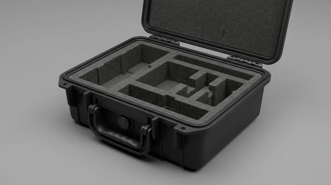
!waterproof protective case with cushioned liner for transporting electroplating line — electroplating line The role of the pressure valve during temperature swings is set out in case pressure equalization valve, and the trade-off between acid resistance and stiffness in shell material appears in aluminum versus stainless steel toolbox comparison.

Packing Lists and the Arrival Re-Inspection Loop
What most often goes out of control on electroplating parts is not the case itself but the mismatch between packing list and arrival inspection. Racks travel in sets, plates in stacks, lined vessels as single pieces. Once mixed, the floor cannot tell which part came from which batch.
| Stage | Recorded data | Purpose |
|---|---|---|
| --- | --- | --- |
| Before packing | Part number, batch, measured contact resistance, hook verticality | Establish the baseline |
| During packing | Case number, per-case part list, cushioning part number, photographs | Build the traceability chain |
| After packing | Case number, gross weight, centre of gravity, stacking limit | Basis for transport and stacking |
| On arrival | Humidity card reading, liner state, lining adhesion state | Decide whether water or acid entered |
| Before start-up | Plate spacing re-measurement, hook verticality re-measurement, inner wall visual check | Decide whether the vessel can run |
Two acceptance criteria must be written into the purchase specification without exception. First, the tank inner wall must be free of scratches and perforations: inspect the full length, concentrating on both sides of welds, the transition between floor and wall, and the lower edge of flange roots. Grazing light is mandatory, because a light held perpendicular hides the shallow scratches. Second, rack contact faces must be free of burrs and pressure marks, and insulating shields must not have shifted: sweep a fingertip across the contact face across the grain, and any resistance means a burr; check with a feeler gauge that the gap between shield and workpiece is even.
Frequently Asked Questions FAQ
Q: A rack is taken out of the bath, not rinsed, and packed straight into a protective case. What actually happens?
A: The result is worse than most people expect, and it is a delayed-onset failure rather than an immediate one. A nickel-chromium salt crust mixed with bath acid absorbs humidity inside the sealed case and turns into an electrolyte, pitting the contact faces and flaking their coatings within 24 to 72 hours. If those contacts are live, the corrosion products shrink the contact area further and unbalance current distribution across the rack. The subtler damage is that acid vapour migrates laterally along the gap between liner and shell, reaching every other rack packed in the same case and turning one neglected item into a whole-case loss. The correct procedure is to rinse in warm water and blow dry after bath exit, sleeve each contact in its own foam cell, and place a pH 3 colour indicator card where it can be read from outside. For journeys longer than seven days, or routes through hot regions, add an extra moisture barrier around the contact group and record the contact resistance baseline before the rack leaves the line.
Q: Shallow scratches on a tank inner wall are hard to find on arrival. Which inspection methods actually work?
A: Visual inspection under perpendicular light only finds scratches wider than 0.1 mm, while most transit damage falls between 0.02 and 0.05 mm, so grazing light is essential. Three practical methods exist. Shine a torch along the vessel axis with the beam held at 5 to 10 degrees to the wall; scratches then appear as broken dark lines across the light band, and the operator can sweep the beam slowly from one end to the other. Next, sweep a fingernail laterally across the surface and judge by the feel of resistance whether any burring has begun. Finally, smear blue or pale detection ink over the wall and wipe it clean, because residual lines inside the depressions reveal damage that bare eye misses. The third method works especially well on rubber-lined tanks, where the pale rubber surface gives low contrast yet responds well to the same technique. Hold the torch at the correct angle every time, since lighting angle is the single variable that decides whether this inspection is useful or worthless.
Q: When a tank must be sectioned for transport, what rules govern where it is cut?
A: The priority order is fixed. Cut at the original manufacturer's flanged joint first, because the bolt holes can be reused. Use a flat region that can be welded on site second. Choose the transition zone between stiffening ribs third, where stress is low and material remains available for a reinforcing plate. Never cut at a rib root or through a weld, since both are stress concentrations to begin with, and cutting there lets residual stress drive a new crack outward from the fresh edge. The underlying logic in every case is to keep the original load path continuous. Where a non-standard cut is unavoidable, fit reinforcing plates on both sides matching the original wall thickness, weld them in the same material on both faces, and subject the seam to liquid penetrant inspection. Each section must then independently verify transport stiffness: model it as a simply supported beam, and under self-weight plus 0.3 to 0.5 g transport acceleration the deflection must stay within 1/500 of the span. A section failing that check needs internal bracing before packing.
Q: What plate spacing should be maintained between anode and cathode plates in transit?
A: Transport spacing is governed by a condition with no liquor and no electrolyte, which makes it stricter than the in-service requirement. In service the gap comes from bath conductivity and target current density, usually 20 to 50 mm. In transit, with the electrolyte gone, any metal swarf can bridge the gap, so the requirement is a clear spacing of at least 25 mm between plates, a continuous partition of 3 mm or more between layers, spacing battens every 200 mm, and battens long enough to cover at least 80 percent of the active plate face. Plate edges need hard corner guards so they cannot puncture the liner and expose themselves. For packaging, each plate is sealed individually in a double PE bag so debris cannot migrate inside it. On arrival, re-measure spacing at one point every 200 mm and record the minimum value; a deviation beyond 3 mm means the vessel must not go into production until the plates are re-registered on the rack and the spacing battens replaced.
Q: Should packing material be selected by medium or by temperature?
A: Both matter, but the priority order is medium and concentration first, temperature second, material form third. The same material behaves very differently under different conditions: polyurethane foam resists weak alkali at room temperature yet hydrolyses and turns tacky within 24 hours in 60 degree C chrome liquor, while PE foam is stable in chromic acid but grows to three to five times its mass once it soaks up residue, becoming a new concentrated load. A PP sheet tank is safe at pH 3 to 11 with residue up to 200 mL over 24 hours, but beyond 48 hours a secondary bagging step is needed. Treat such tables as a starting point only, and always validate by immersion using an actual liner sample from the same batch: soak it under the real process temperature and concentration, then measure permanent compression set and inspect for surface tackiness, discoloration and dimensional change. Above 25 percent permanent compression set the cushion is judged failed, and the sample is discarded rather than returned to the liner stock.
Q: Can electroplating line cases be reused, and what must be checked before each reuse?
A: Yes, provided the case body is intact and the liner can be fully renewed. Four checks are mandatory before reuse. Verify sealing integrity by inspecting every seal groove for crystals, adhesive residue or debris left from the previous load. Confirm that the pressure equalisation valve still breathes, using a differential pressure method or a listening check. Examine corner guards and latch blocks, because internal micro-cracks appear in plastic corners after repeated impact and corners should be replaced on a fixed cycle even when they look intact externally. Finally, measure compression set on a test block of the nominal foam thickness and renew the liner beyond 30 percent. Cases from plating areas carry one extra risk: residual acid vapour accelerates hardware corrosion, so a periodic full clean and hardware inspection is worthwhile. Fitting a QR asset code to the case side lets staff track turnover cycles and base replacement on evidence rather than habit, and keeps transport records, liner batch numbers and damage reports linked to individual cases.
Q: If a strong acid-fog smell is detected on arrival, may the parts go straight into production?
A: Not advisable. Open the case, inspect, and isolate the affected items first. Work through a fixed sequence: read the humidity indicator card to establish whether water ingress occurred, check whether the acid-fog card triggered to establish fog intensity, then open the case and examine the liner surfaces and the first parts nearest the leak path. There are two possible origins for the smell. One is residue sealed in without draining, which is the packer's responsibility. The other is seepage through a tank weld, flange root or nozzle, which is a manufacturing defect that escaped the pre-shipment check. Distinguish them by looking for fresh damp marks or crystallised salts at flange roots and welds. Once acid fog is confirmed, rack contact faces are almost certainly affected and each contact resistance should be measured; tanks need their lining checked for blistering and delamination; and PP or PVC sheet needs a check for surface tackiness and stress cracking. Retain photographs and test data afterwards as the input to the next packing revision.
Q: Can the rectifier, heater and filter be packed in the same case as the tanks and racks?
A: Mixing them is not recommended, even where the volume would technically allow it, because the humidity and temperature conditions differ enough to damage each other. A rectifier is an electrical assembly whose electronics need relative humidity below 60 percent, while tank transport routinely exposes the case interior to 90 percent and above. A heater and a temperature sensor sharing one chamber let residual heater heat shift the sensor baseline and corrupt the control loop after start-up. A filter cartridge sharing space with any coarse liner will have its pleat pack loaded with particles that shorten filter life. Splitting the load into separate chambers is therefore better: the electrical chamber gets its own desiccant and humidity indicator, brittle assemblies are fully suspended with zero contact pressure, and heavy assemblies sit in the lower compartment with their own compression calculation. Where transport volume forces a mixed load, electrical items must go into sealed moisture barrier bags with humidity cards, separated from every wet part by a physical partition wall.
Conclusion and Related Reading
Transport protection for electroplating parts is a precise mapping between in-service precision and transit mechanics. JUNZHIJIA customises plating rack and tank cases around bath medium, vessel size and turnover frequency, supplied by Kexin New Materials (Guangdong) Co., Ltd.
Related Reading