


A magnetic drive pump replaces the mechanical seal with a static barrier: torque crosses a thin containment shell through the field of two magnet rotors. That is why chemical, pharmaceutical, electronic-grade chemical and battery-precursor plants with zero tolerance for leakage run them at scale. The parts that make this possible, however, are the most fragile items in the whole pump. Sintered neodymium magnets are hard but brittle, and once the plating is breached the substrate corrodes and crumbles. Containment shells are frequently thinner than two millimetres and lose stability the moment a point load lands on them. Silicon carbide bearings and sleeves work with clearances measured in microns, where a single grain of sand is enough to scrap a pair. JUNZHIJIA's position is that protecting magnetic drive pump spares is not mainly about surviving a drop. It is about preventing demagnetisation, preventing shell collapse and preventing contamination, and that requires compartmented location, rigid load-bearing structure and clean sealing used together. A generic foam-filled case cannot deliver any of the three.
In real spare-parts and export projects, magnetic drive pump damage rarely shows up as a smashed crate. It shows up as a component that looks perfect and leaks the moment it is installed. Magnets pull toward each other inside the box and collide, and the flux loss is invisible until the pump runs hot with insufficient torque transfer. A shell face pressed by the flange of the part stacked above it develops a slight ovality, and the eddy-current losses climb until process fluid finds a path. A silicon carbide sleeve loses one small corner, which is harmless at start-up and destructive a few hundred hours later when the fragment laps the shaft journal. All of these failures surface late, and by then the component is in a plant on the other side of the world. This article is written for equipment engineers at chemical and pharmaceutical plants, spare-parts warehouse managers and project logistics leads. It works through magnetic coupling, containment shells, sliding bearings, cleanliness, moisture and corrosion control, case structure and acceptance documents, and gives executable parameters and inspection methods at each step so that incoming spare quality stops being a lottery.
Table of Contents
- Risk Map for Magnetic Drive Pump Component Transport
- The Magnetic Coupling Assembly: Impact and Demagnetisation Control for Neodymium Magnets
- Containment Shells: Preventing Compression Damage in Thin Carbon Fibre, Ceramic and Hastelloy Designs
- Sliding Bearings and Sleeves: Protecting Precision Mating Faces and Keeping Them Clean
- Inner and Outer Magnet Rotors: Preserving Assembly Faces and Balance Marks
- Cleanliness Control in ISO 4406 and ISO 14644 Terms
- Moisture and Corrosion: Chloride Environments and Salt Spray Protection
- Liners and Compartments: Material Selection and Structural Design
- Case Sealing, Latches and Pressure Equalisation
- Lifting, Stacking and Transport Test References
- Marking, Traceability and Incoming Inspection
- Selection Checklist and Configuration Table
- Maintenance, Rotation and Case Service Life
- OEM/ODM Customisation and Project Delivery
- FAQ
- Conclusion and Further Reading
Risk Map for Magnetic Drive Pump Component Transport
Before designing a case that actually works, it helps to be precise about how a magnetic drive pump fails. Compared with an ordinary centrifugal pump, the magnetic design moves the leakage risk away from the shaft seal and onto the containment shell and the magnetic coupling. That shift also rewrites the transport damage list.
The first category is flux loss. Neodymium iron boron is a hard magnetic material whose remanence and intrinsic coercivity are sensitive to temperature, opposing fields and mechanical shock. Routine handling at ambient temperature does not change the magnetisation state, but two magnets that snap together after being drawn across a compartment collide at speed, and the local stress and micro-cracking at the impact site weaken performance locally. Long exposure to a hot trailer or the top layer of a container, where internal air can exceed sixty degrees Celsius in summer, pushes the magnet past its reversible temperature limit and accumulates irreversible loss. The second category is shell instability. Metal containment shells are thin-walled rotating parts, often between 0.3 and 1.0 mm, while non-metallic shells are thicker but markedly more brittle. Both share the same enemy: point loads and stack pressure, where the weight of the part above transfers through foam into a concentrated force that dents the shell along its generatrix. The third category is contamination of mating faces. Sliding bearings and sleeves are lubricated by the process fluid itself, so the cleanliness at packing time sets the initial wear rate, and dust, fibres, metal powder and skin oils are all critical contaminants. The fourth category is corrosion. Once the nickel-copper-nickel or epoxy coating on a magnet is chipped, the exposed neodymium iron boron oxidises quickly, the oxide swells and lifts more coating, and the damage becomes self-accelerating. Hastelloy shells resist corrosion well, yet weld heat-affected zones and flange sealing faces can still pit and crevice-corrode in chloride service.
The table below maps the main components to their failure paths and the corresponding protective measures. It can be used directly as a pre-packing checklist.
| Component | Typical material | Main transport failure | Protection focus |
|---|---|---|---|
| --- | --- | --- | --- |
| Inner and outer magnet rotor | Sintered NdFeB with Ni-Cu-Ni plating, stainless over-wrap | Mutual attraction impact, coating breach, irreversible high-temperature flux loss | Single-piece compartments, magnetic shielding boxes, temperature control |
| Containment shell | Carbon fibre composite, zirconia or silicon carbide ceramic, Hastelloy C-276, PEEK | Point-load denting, ovality, face chipping, weld micro-cracks | Rigid support sleeve, no stacking, protective face rings |
| Sliding bearing and sleeve | Pressureless sintered SiC, tungsten carbide, graphite, PEEK | Edge chipping, scoring of mating faces, embedded particles | Individual wrapping, clean cavity, no oil film |
| Pump shaft and journal | 316L, duplex stainless, Hastelloy | Bending, chrome layer scoring, thread damage | Axial support, corner guards, thread protectors |
| Flanges and seals | FKM or FFKM O-rings, PTFE gaskets | Compression set, dust adsorption, ageing | Flat storage without stacking, light protection, desiccant |
| Casing and baseplate | Cast iron or stainless precision casting | Chipping, sealing face bruising, rust | Compartment location, face isolation, rust-preventive wrap |
The mutual attraction of magnets deserves its own note. Once unwrapped, magnets placed side by side jump together, because the attractive force rises steeply as the gap closes. A small block weighing a few hundred grams can pinch a palm within a few centimetres. Inside a case, if two magnet rotors share one cavity with only a few millimetres of foam between them, vibration compresses that foam and one bump completes the journey into contact. The rule JUNZHIJIA applies in magnetic drive pump cases is one magnet per cavity, with a magnetic barrier between cavities, using stainless or galvanised steel sheet. This suppresses mutual attraction and also keeps stray external flux within the limits that allow air freight. It follows the same logic used in MRI magnet transport protection for shielding and temperature control.
The Magnetic Coupling Assembly: Impact and Demagnetisation Control for Neodymium Magnets
The magnetic coupling assembly consists of an inner rotor on the process side, an outer rotor on the atmosphere side, and the containment shell between them. The inner rotor normally carries NdFeB blocks embedded in a stainless or carbon fibre over-wrap and potted in resin, while the outer rotor is keyed to the motor shaft. The first concept to establish when packing these parts is that a magnet behaves like a ceramic. The flexural and tensile strength of sintered NdFeB is far lower than its compressive strength, so it does not deform like steel under impact. It cracks, and the crack usually propagates along the adhesive interface between blocks.
Single-piece isolation is therefore the first rule of packing. Every rotor and every loose magnet block must have its own cavity, lined with closed-cell foam or EVA selected for low compression set. Wrap thickness scales with mass: ten to fifteen millimetres for small blocks, twenty to thirty millimetres for medium rotors, and a rigid radial support ring for large outer rotors above roughly four hundred millimetres in diameter, so that foam alone is never the constraint. The second rule is shielding and pairing control. When inner and outer rotors ship as a matched pair, each goes into its own low-carbon steel shielding box or silicon-steel-lined compartment. The box short-circuits the magnetic circuit, greatly reducing the attraction between neighbouring magnets, which matters most for air freight, since aviation rules require magnetic shipments to be assessed against a surface field-strength limit before they can travel as general cargo. The third rule is temperature. On long sea voyages and summer road legs, magnet cases should not be stacked at the top of a container or left in direct sun. A temperature indicator label inside the case turns an invisible risk into a record, and any excursion above the magnet grade's working limit should trigger flux verification or the manufacturer's torque check on arrival.
Rust prevention is the other half of magnet care. The NdFeB substrate oxidises readily and depends entirely on its coating, so any impact that breaches the coating starts a corrosion site. Every piece should be inspected for coating integrity before packing; damaged items are marked separately and wrapped with rust-preventive paper rather than mixed with conforming parts. Silica gel desiccant at fifty to eighty grams per cubic metre of cavity volume, combined with an aluminium foil laminate bag, creates a local low-humidity environment. Liner materials in contact with magnets must be free of sulphur and chlorine-bearing plasticisers, since leachables attack the coating. The illustration below shows a magnet rotor in its own compartment with a magnetic barrier and shielding box between cavities.
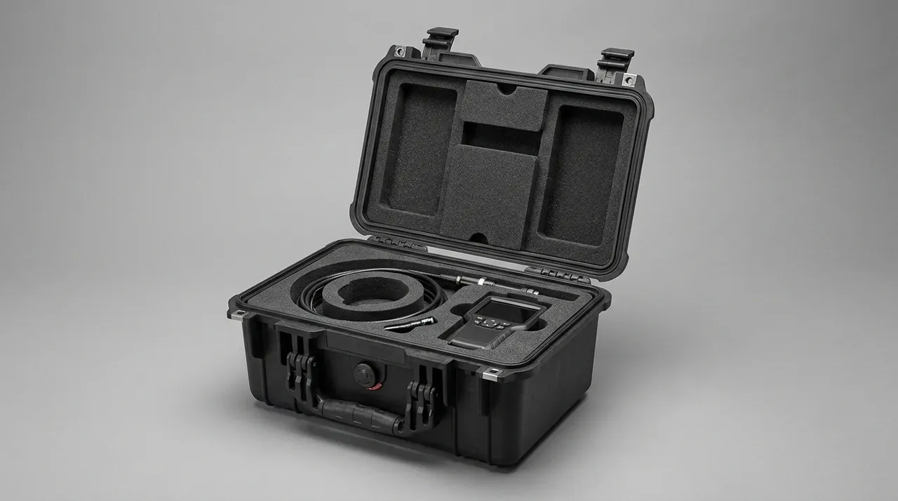
One caution: a shielding box is itself a heavy object, and its weight must not travel through foam onto the parts below. Structurally the box should sit directly on the load-bearing frame of the case base, with a ten to fifteen millimetre air gap to neighbouring compartments, which separates both magnetically and vibrationally. If a customer requires the inner and outer rotor to ship as one assembly, the pair must be locked together with the manufacturer's fixture and marked for orientation. Shipping them loose is not acceptable, because re-aligning them in the field directly affects axial offset and coaxiality of the coupling.
Containment Shells: Preventing Compression Damage in Thin Carbon Fibre, Ceramic and Hastelloy Designs
The containment shell is the heart valve of a magnetic drive pump. It isolates process fluid from atmosphere while letting the magnetic field pass through. That dual duty makes it the hardest part in the pump to transport. Shells fall into three material families, each with a different protection priority.
Metal shells are typically Hastelloy C-276, titanium or 316L, between 0.3 and 1.0 mm thick, formed by spinning or deep drawing, with the base joined to the flange by electron beam or laser welding. Their failure mode is elastic instability. A thin-walled cylinder has a critical buckling pressure under external load, and once a local dent forms, strength drops sharply and the dent can fatigue-grow under cycling pressure in service. Metal shells must never be stacked, no rigid object may be inserted into the bore, and the sealing face requires a plastic protective ring. Non-metallic shells include carbon fibre reinforced PEEK or PTFE composites, plus zirconia and silicon carbide ceramics. The composites are tougher but weak in compression, while ceramics are hard, chemically excellent and distinctly brittle: an edge or face that contacts anything hard chips immediately, and the damage cannot be repaired. Ceramic shells are especially sensitive to point contact. Any hard particle trapped between the shell and its liner will press a micro-indentation into the surface under vibration, and that indentation becomes a stress raiser in service.
The table below summarises transport sensitivity and recommended protection for the three families.
| Shell type | Typical wall thickness | Transport sensitivity | Protection configuration | Service note |
|---|---|---|---|---|
| --- | --- | --- | --- | --- |
| Hastelloy C-276 | 0.3 to 1.0 mm | External pressure buckling, sealing face bruising, weld micro-cracking | Rigid support sleeve plus face rings, no stacking, no rigid inserts | Aggressive and chloride-bearing media |
| Carbon fibre reinforced composite | 0.8 to 2.0 mm | Delamination, edge chipping, creep under sustained compression | Fully wrapped closed-cell liner plus axial restraint, no sustained point load | Applications needing low eddy-current loss |
| Ceramic (zirconia, silicon carbide) | 1.0 to 2.5 mm | Chipping, micro-cracking, point-contact indentation | Soft liner, particle-free cavity, separate compartment | High-purity and abrasive media |
The structural principle is to take the load off the shell wall. In practice, each shell gets a rigid support sleeve matched to its outside diameter and length, made from engineering plastic or an aluminium frame. The sleeve carries stacking and vibration loads while the shell supports only its own weight. A chamfered protective ring goes on each end, with an outside diameter slightly larger than the flange, so the ring contacts the ground first in a drop. A soft locating plug inside the bore stops axial movement within the cavity but must not apply radial pressure. For ceramic shells, a layer of non-woven fabric between shell and liner blocks any hard particle that finds its way in. JUNZHIJIA's experience with thin-walled rotating parts follows the same principle described for centrifuge rotor transport cases, where a support cradle carries the load and the rotor carries itself, and the stiffness check method can be borrowed directly.
The illustration below shows a shell in a rigid support sleeve with chamfered face rings, where the load path runs from the sleeve into the case frame and the wall carries only self-weight.
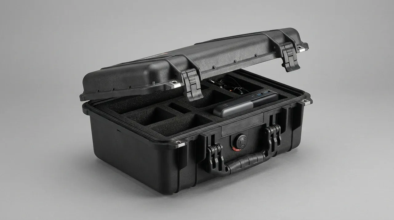
Pre-packing inspection must cover face flatness with a straight edge and feeler gauge, roundness with an inside micrometer or coordinate measuring machine, and a strong side-light visual check of welds and ceramic surfaces for cracks and chips. A shell that fails any of these should not enter a transport case at all, because the damage is neither repairable nor reliably detectable on arrival. When shells travel in the same case as magnet rotors, place them in the middle of the case with rigid support above and below, never at the edge where lateral compression acts.
Sliding Bearings and Sleeves: Protecting Precision Mating Faces and Keeping Them Clean
Magnetic drive pumps generally use process-lubricated sliding bearings. Common pairings are silicon carbide against silicon carbide, silicon carbide against graphite, and tungsten carbide against silicon carbide, with PEEK or filled PTFE for special duties. Clearances are measured in hundredths of a millimetre and are set by fluid viscosity, speed and temperature rise, so bearings ship as matched sets to drawing. If one half is scratched or mixed with the wrong partner in transit, the whole assembly is compromised.
The first requirement is that mating parts must never be stacked as a set. Bearings and sleeves get individual wrapping in lint-free cloth or antistatic foam before going into their compartments. Sliding a sleeve over a bearing outer ring to save space looks efficient and is a mistake: vibration turns two hard surfaces into a lapping pair, and a few hours on the road leaves ring-shaped scoring. The second requirement is edge protection. Silicon carbide and tungsten carbide are extremely hard and low in fracture toughness, and the bore chamfer and outer edge are stress concentrators that need a soft protective ring or heat-shrink sleeve. The third requirement is no oil. Many bearings are graphite or resin-impregnated, and mineral oil migrates into the porosity and slowly leaches into the process fluid, contaminating it. Pack dry instead, isolate humidity with vapour-phase corrosion inhibitor paper and include a humidity indicator card. If a customer specifies long-term storage protection, apply only the manufacturer-approved preservative compatible with the process fluid and label the grade and application date.
Cleanliness is the other half of this section. Magnetic drive pump bearings tolerate contamination far less than a conventional sealed pump: hard particles a few tens of microns across will cause measurable wear during run-in. The packing area should meet at least ISO Class 8 according to ISO 14644, benches should be covered with a non-shedding mat, operators should wear powder-free gloves and antistatic finger cots, and shredded corrugated board, straw and crumb foam are all prohibited. For spares shipped to semiconductor and pharmaceutical customers, a cleanliness declaration inside the case stating liner material, cleaning method and verification basis is often worth more during customer qualification than the case itself.
Inner and Outer Magnet Rotors: Preserving Assembly Faces and Balance Marks
Inner and outer magnet rotors are balanced and magnetised before dispatch, and they normally carry balance correction holes, weight mounting positions, keyways and orientation marks. The integrity of those marks determines whether the field assembly goes quickly or becomes a rework job, and they are precisely the features most easily disturbed in transit.
Preserving balance marks means they must not be covered, wiped or cleaned with solvents that swell the ink. If a balance weight works loose, the field team has to rebalance from scratch, and without the original correction data that means balancing the whole rotating assembly, which is expensive. Weights should be torque-checked before packing, marked for security, and the case labelled to show that balanced parts must not be dismantled. Keyways and dowel holes get plastic plugs so dust cannot enter and damage the fit during assembly. Shaft journals and seal seats are wrapped with protective tape and fitted with a guard sleeve, wound opposite to the removal direction so the field team can strip it easily.
Outer magnet rotors are usually larger and heavier with more exposed magnet surface, so they ship in the horizontal orientation specified by the manufacturer to avoid the shaft and hub joint loosening under sustained cantilever load. Where an outer rotor connects through a coupling half, the coupling teeth or diaphragm pack are high-precision items that need their own compartment and rust-preventive wrap. In projects delivered as a complete pump unit, the pump head and motor go into two compartments of the same case separated by a rigid divider that carries lateral load, and the motor weight must never rest on the pump flange. This compartment logic is the same approach used for diaphragm pump component cases, where pump head, gearbox and valve manifold are located in separate zones, and the compartment sizing method can be cross-referenced.
Cleanliness Control in ISO 4406 and ISO 14644 Terms
Cleanliness for magnetic drive pump spares is not a vague idea that cleaner is better. It has to become a measurable acceptance criterion. Two standards frameworks describe it. ISO 4406 rates the solid particle contamination level of hydraulic and lubricating fluids by counting particles in the greater-than-four, greater-than-six and greater-than-fourteen micron bands. ISO 14644 rates airborne cleanliness in cleanrooms. The relationship is straightforward: packing controls residual particles on surfaces and inside cavities, those particles end up in the process fluid or lubricant after assembly, and the result shows up as a degraded ISO 4406 code.
In practice, set three measurable control points in the packing process. First, part cleanliness. Bearings, sleeves and containment shells should be cleaned to the manufacturer's procedure before packing, using ultrasonic or spray methods, with particle counting on the verification fluid. A typical acceptance target is a verification fluid result no worse than 17/15/12 on the ISO 4406 scale, tightened further for semiconductor-grade applications. Second, packing environment. Air cleanliness in the kitting and sealing area should be no worse than ISO Class 8, with bench airflow and operator gowning following cleanroom practice. Third, packaging materials. Liner foam and bags need traceable cleanliness and particle-shedding ratings, because cleaning a part thoroughly and then dropping it onto shedding foam undoes the work.
These three control points belong in the documents that travel with the case, tied to incoming inspection clauses. Where a contract specifies cleanliness, JUNZHIJIA can supply cleaning method statements, packaging material lists and sampling record templates so that the customer can fold the packing step into their own supplier quality system rather than treating it as a black box. The compartment and cleaning workflow is described further in the clean-grade liner section of the custom foam insert guide.
Moisture and Corrosion: Chloride Environments and Salt Spray Protection
Magnetic drive pump spares frequently end up at coastal chemical parks or overseas ports, where a container spends weeks at sea through day-night temperature swings and high humidity, with internal relative humidity often above eighty percent and condensation forming on metal surfaces. For this equipment family, the consequences of corrosion are magnified. Any breach in magnet coating starts substrate oxidation, the swelling lifts more coating, and the cycle accelerates. Weld heat-affected zones in Hastelloy and stainless shells can pit and crevice-corrode in chloride service. Stainless fasteners seize in damp salt air, which makes field disassembly painful.
Moisture control follows a three-step order: dry first, barrier second, monitor last. Drying means removing all water from parts before packing, including bores, blind holes and threads, with no wet packing permitted. The barrier is an aluminium foil laminate or high-barrier film forming a local sealed volume with desiccant inside and heat-sealed seams. Monitoring means a humidity indicator card or temperature-humidity data logger in the package so that incoming inspection can tell whether moisture ingress occurred. For air freight and short road legs, vapour-phase corrosion inhibitor film can replace desiccant: the inhibitor vaporises inside the sealed volume and protects cast iron, carbon steel, stainless steel and plated surfaces, but it must be kept away from sulphur or chlorine-bearing liner materials.
Salt spray performance can be evaluated using the neutral salt spray method defined in GB/T 10125, comparing candidate surface treatments such as zinc plating, zinc flake coatings, passivation and powder coating under identical conditions, and using the results to decide the finish for case hardware and internal supports. Note that the case requirement should be kept separate from the component requirement: components are selected for media and duty, while case hardware is selected for the transport environment, and the two specifications should not be merged into one document. For cases rotated outdoors over long periods, corrosion design at seams and latches matters most, and the guidance on stainless hinges, over-centre latches and gasket compression in the article on toolbox hinge, latch and seal structure applies directly.
Liners and Compartments: Material Selection and Structural Design
The liner determines cushioning, location, cleanliness and static behaviour all at once. For magnetic drive pump parts, evaluate four properties together: compression set, shedding tendency, static dissipation and chemical inertness. Compression set decides whether the liner still grips after long stacking. Shedding decides whether cleanliness survives packing. Static behaviour decides whether magnetic debris and dust cling to surfaces. Inertness decides whether the liner leaches anything that attacks magnet coating or elastomer seals.
The table below compares common liner materials for this application.
| Liner material | Compression set | Shedding tendency | Static behaviour | Typical location |
|---|---|---|---|---|
| --- | --- | --- | --- | --- |
| Closed-cell EVA | Low | Low | Antistatic grades available | Main locating blocks for rotors and shells |
| Cross-linked PE (XLPE) | Low | Low | Moderate | Load pads and base layers for heavy parts |
| PU foam | Low | Very low | Moderate | Precision mating faces and bearing compartments |
| PE pearl foam | Medium | Medium | Prone to static build-up | Filler for non-critical parts only |
| Non-woven or lint-free cloth | Not applicable | Very low | Antistatic grades available | Direct contact layer on precision faces |
Structurally, a magnetic drive pump case should be layered and compartmented rather than uniformly filled. The base layer carries the heaviest and most vibration-tolerant items such as casing and flanges. The middle layer holds containment shells and magnet rotors, framed by a rigid skeleton that takes stack load. The top layer holds bearings, sleeves, seals and small hardware. Each compartment is routed slightly deeper than the part thickness so the part sits below the compartment rim by five to ten millimetres. Compartment walls should be at least eight millimetres thick with radiused or chamfered contact edges, so no sharp edge cuts into a part surface under vibration. Removable compartment systems make field counting and spare substitution easier; the modular approach in the article on the removable divider system can be adapted directly. For static-sensitive electronic-grade applications, antistatic liner surface resistance should sit between 10⁶ and 10⁹ ohms and be bonded to the case earth terminal, so handling cannot discharge through magnet coating or attached sensors.
Case Sealing, Latches and Pressure Equalisation
Because these spares are moisture-sensitive, case sealing is a critical link in the protection chain. Ingress protection is classified under IEC 60529 and GB/T 4208, and this class of spare-parts case normally needs IP67 for short-term immersion or IP65 for water jets, depending on transport and storage conditions. Achieving IP67 depends not on the gasket alone but on the match between gasket material, compression ratio and case stiffness. Gaskets are usually foamed silicone or hollow extruded EPDM, with compression between twenty-five and thirty-five percent. Too little and the joint leaks; too much and the gasket takes a permanent set that stops the lid sealing after a few cycles. Wall thickness and ribs must prevent the lid from bowing in the middle, because bowing starves the longest edge of compression.
Latches and hinges are the second decisive factor. Rotary or over-centre latches apply sustained closing force, and if they are spaced too widely the lid lifts between them and opens a leak path. A practical rule is one latch every three hundred to four hundred millimetres along the long edge, with stainless hinge pins and anti-loosening treatment so that hinge clearance does not grow and misalign the lid over years of use. The interaction between gasket compression and latch spacing is set out in the article on toolbox hinge, latch and seal structure, and magnetic drive pump cases can adopt those rules directly.
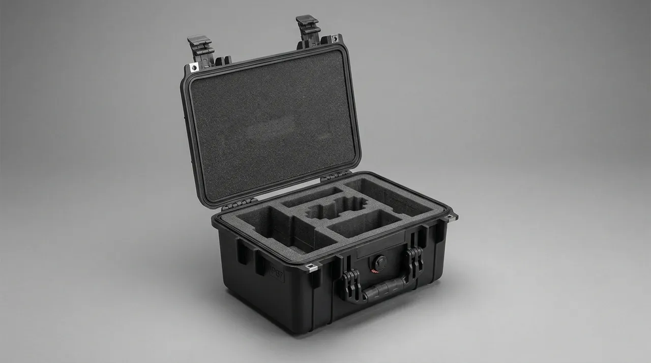
The third step is usually the one that gets forgotten: pressure equalisation. Even a perfectly sealed case meets a pressure differential when an aircraft climbs or a truck crosses a high plateau, and a drop of tens of kilopascals is enough to bulge the case, push the gasket off its seat and distort the lid, so that it either will not open or will not seal again after landing. The answer is a one-way pressure equalisation valve in the case wall that passes air slowly while blocking liquid water and dust, preserving the overall ingress protection rating. For magnetic drive pump spares travelling by air or over high-altitude roads, the valve is not optional. Selection points are covered in the article on the case pressure equalisation valve. The illustration below shows a shell support sleeve, magnetically shielded compartments and a pressure equalisation valve arranged in one case.
Lifting, Stacking and Transport Test References
A magnetic drive pump case is not in the heavy equipment category, but when matched coupling assemblies ship with shielding boxes, a single case can weigh eighty to one hundred and fifty kilograms and still needs proper lifting and stacking design. Define lifting points and sling angles, and provide forklift pockets in the base at least ninety millimetres high with steel reinforcement so forks cannot punch through the floor. Mark the centre of gravity and lifting orientation on the case face, and never sling the case with wire rope, because the clamping force travels through the walls into precision parts.
Verify stacking strength against the worst case: unit mass multiplied by design tiers and then by a safety factor, typically 1.5. That load must be carried jointly by the case walls and an internal rigid skeleton, never by liner foam. The liner absorbs shock and vibration and carries no static load. This is the rule most often violated in magnetic drive pump case design.
Transport test references depend on destination and customer requirements. Commercial packaging for North American distribution can follow ISTA series procedures such as ISTA 2A and 3A, covering drop, vibration, compression and combined temperature-humidity conditioning. Domestic Chinese transport can reference the GB/T 4857 series. Complete-equipment export projects can use the ASTM D4169 distribution cycle, selecting severity to match the actual route. For environmental suitability, MIL-STD-810H vibration and shock methods can be cited as methodology references only, since that standard does not confer any military certification, and IK ratings can be used to characterise case impact resistance. For packages containing magnets, add a post-test flux verification step, because vibration and drop effects on magnets cannot be judged by appearance.
Marking, Traceability and Incoming Inspection
Package marking should follow GB/T 191 for handling pictorial marks, including at minimum fragile, keep dry, this way up, stacking limit and do not roll, with a magnetic field warning label for magnet shipments and a flux test statement where the carrier requires one. General requirements for mechanical and electrical product packaging are covered by GB/T 13384, including case structure, liner fixing and documentation completeness. For shipments into the European Union and similar markets, wood packaging must meet ISPM 15 treatment requirements, or the design should switch to plywood, honeycomb board and foam composites to avoid fumigation delays.
Traceability should bind case, part and document together. Every part has a fixed compartment position number, the case carries a packing list with model, drawing number, batch number, measured flux or magnetic moment, balancing record and cleanliness declaration, and a unique identifier on the outside links back to the manufacturing batch and inspection records. Where a customer runs first-article approval, supply key dimensional reports together with measured shell face flatness and roundness.
Incoming inspection should run in a fixed order. Check the outer case for drop marks, water staining and whether the pressure equalisation valve is blocked. Open the case and reconcile the packing list with the contents. Inspect every magnet for coating integrity, every shell face and weld, and every bearing mating face for scoring. Sample magnets with a flux meter or gaussmeter and compare against the shipped values, treating any deviation beyond the manufacturer's tolerance as a demagnetisation risk. Read humidity indicator cards and temperature loggers. Finally, re-measure shell roundness and face flatness in a clean area. Isolate the whole case if any critical item fails, rather than releasing the good parts. This logic can be combined with the sampling rules in the article on custom case acceptance and AQL, turning subjective judgement into a recorded decision.
Selection Checklist and Configuration Table
A magnetic drive pump case is not a catalogue item. It should be configured against the pump model, the parts list and the transport route. The table below is a configuration template that can be sent out for quotation as it stands, with the customer filling in specifications and quantities.
| Configuration item | Options | What to specify |
|---|---|---|
| --- | --- | --- |
| Case size and type | Carry case, mid case, wheeled case, split large case | Largest item envelope plus liner allowance |
| Case material and rating | Copolymer polypropylene, glass fibre composite, aluminium; IP65 or IP67 | Air freight, sea freight and storage environment |
| Magnetic shielding compartments | Low-carbon steel boxes, silicon-steel lined compartments, stainless dividers | Part numbers needing shielding and allowable external field |
| Liner system | EVA, XLPE, PU, antistatic foam | Cleanliness class, static requirement, contact face material |
| Rigid load structure | Aluminium frame, steel support sleeve, shelf supports | Unit mass and stacking tiers |
| Sealing and accessories | Foamed silicone gasket, pressure equalisation valve, humidity indicator card | Air freight requirement and storage duration |
| Hardware | Stainless hinges, over-centre latches, forklift pockets, lifting points | Surface finish driven by salt spray requirement |
| Documentation | Packing list, inspection report, cleanliness declaration, flux record | Confirm item by item against the quality agreement |
The most common error when filling this table is sizing the case for the largest part and the liner for the smallest. The case is driven by the largest item, but compartment count and depth must cover every part number and reserve dedicated cavities for vulnerable items such as shells, bearings and magnet rotors. If a case carries both strong magnets and precision electronic accessories such as vibration sensors or temperature probes, a magnetic barrier must separate them and the electronics must have their own antistatic shielded packaging, following the shielding and earthing practice described for ESD shielded cases.
Maintenance, Rotation and Case Service Life
Reusable spare-parts cases cut long-term operating cost substantially, provided a maintenance routine exists. The gasket is the first consumable. EPDM and silicone gaskets harden and lose resilience under ultraviolet light, ozone and repeated compression, so check compression set every twelve to twenty-four months, and after each closure check that a continuous impression appears on the case wall. Latch springs and hinge pins are the second wear point: when they loosen, bind or lose clamping force, replace the whole component rather than adjusting it. Liner foam eventually takes a compression set and powders, and antistatic foam loses conductivity as it ages, so evaluate surface resistance every two to three years.
Rotation control should bind case to contents. Give each case a unique number and register its compartment liner and accessories, including desiccant, shielding boxes and indicator cards, as assets of that case, so that after several trips the liner is not missing and precision parts are not travelling bare. For magnetic drive pump spares, add a flux re-verification interval per trip and a replacement rule for shielding boxes after impact, since a deformed box changes the magnetic circuit in a way that no visual inspection can reveal.
OEM/ODM Customisation and Project Delivery
When a magnetic drive pump manufacturer exports spares, the packaging often has to fit into a complete-unit delivery system, with branded cases, dedicated compartments, technical documentation and co-packing alongside the main crate. JUNZHIJIA can reverse-engineer liner models from customer drawings or physical samples and provide customisation from single spare-parts cases to full unit packing sets, supporting OEM and ODM cooperation with case colour and silk-screen branding, liner tooling, model-specific seal and accessory kits, and customised document templates. For overseas distributors holding long-term spare inventories, a standardised packing scheme that maps model, compartment and document one-to-one means warehouse storage and onward shipping need no new liner work.
For the delivery workflow, ask customers to supply four inputs at enquiry stage: parts list with envelope dimensions, unit mass and centre of gravity, transport route by road, sea or air together with destination climate, and the cleanliness and traceability requirements in their quality agreement. With those inputs, case structure, liner scheme and document list can be fixed together, avoiding the rework that comes from building the case first and writing the documents afterwards. For air cargo containing magnets, confirm the carrier's assessment and declaration route for magnetic shipments early, so compliance risk is designed out rather than discovered at the airport.
FAQ
Q: Do neodymium magnets really lose strength during ordinary transport, and is shielding necessary?
A: At ambient temperature and in the absence of strong opposing fields, the magnetisation of a sintered NdFeB magnet is stable, and normal transport vibration is not enough to demagnetise it overall. The real risks are three. First, neighbouring strong magnets can attract and collide, and the local stress at impact weakens magnetic performance locally and can initiate cracks. Second, exposure to temperatures near or above the magnet grade's working limit, which happens on the top layer of a closed container in summer, causes irreversible flux loss. Third, external fields can interfere. Shielding therefore mainly suppresses mutual attraction and supports air-freight compliance assessment rather than preventing spontaneous demagnetisation. In practice, give every magnet its own compartment, put a steel barrier or shielding box between compartments, include a temperature indicator label, and sample flux or magnetic moment on arrival against the shipped record, treating deviation beyond the manufacturer's tolerance as a red flag. Record the ambient temperature history alongside the flux reading, because the two together tell you whether the cause was thermal or mechanical.
Q: The containment shell wall is only 0.5 mm thick. Is full foam wrapping enough?
A: No. Foam provides cushioning and prevents abrasion but cannot deal with stacking load or point load, which are the two failure modes that matter most for thin walls. A half-millimetre cylinder has a low critical buckling pressure, and the weight of parts above still arrives as a concentrated force after passing through foam. Long stacking or repeated vibration leaves a dent along the generatrix, which shows up in service as higher eddy-current loss and leakage toward the process side. The correct approach gives every shell a rigid support sleeve that carries stack load so the shell supports only its own weight, adds chamfered protective rings at both ends, and fits a soft locating plug inside the bore that applies no radial pressure. Ceramic shells also need a non-woven layer between shell and liner to block hard particles. Before packing, sample face flatness and roundness and inspect welds and surfaces under strong side lighting. Store shells upright in the support sleeve, never resting on the flange face.
Q: Should sliding bearings and sleeves be coated with rust-preventive oil before packing?
A: As a rule, no. Magnetic drive pump sliding bearings are usually silicon carbide, tungsten carbide, graphite or resin-impregnated, and graphite and impregnated grades are porous. Mineral oil migrates into the porosity and leaches slowly into the process stream, which is unacceptable for pharmaceutical and electronic-grade duties, and an oil film also captures dust and increases contamination of the mating faces. Keep parts dry instead, isolate humidity with vapour-phase corrosion inhibitor paper or lint-free cloth, include a humidity indicator card in the package, and wear powder-free gloves during packing. Where a customer explicitly requires long-term storage protection, apply only the preservative approved by the manufacturer for compatibility with the process fluid, label the product grade and application date, and clean to procedure before installation. Clearances here are set at hundredths of a millimetre, so an oil film of uncontrolled thickness can also hide damage during inspection: a scored face looks smooth under grease and is only revealed after cleaning at the plant, once the claim window has closed. If something must be applied, restrict it to the shaft journal, keep it off every carbon and ceramic sliding surface, and state on the label exactly what was used.
Q: ISO 4406 is a fluid cleanliness standard. How does it apply to packing?
A: ISO 4406 describes the solid particle contamination level of a fluid by counting particles in the greater-than-four, greater-than-six and greater-than-fourteen micron bands, so it does not directly regulate packaging. What it does provide is a way to quantify cleanliness, which can then constrain the packing process from the other direction. First, require parts to be cleaned to procedure before packing and the verification fluid to be particle-counted, converting the result to an ISO 4406 level with a defined ceiling. Second, control air cleanliness in the kitting and sealing area to at least ISO Class 8 under ISO 14644. Third, require traceable shedding ratings for liner and packaging materials. Writing these three control points into the documents that travel with the case and linking them to acceptance clauses turns packing from a black box into a step the customer can audit inside their own supplier quality system. Keep those records short and specific: cleaning agent, bath temperature, ultrasonic duration, drying method, particle count and the level achieved. A single page a customer quality engineer can compare against incoming data is more persuasive than a long generic statement.
Q: Does a magnetic drive pump case have to be IP67?
A: It depends on the transport and storage route. IP65, protecting against water jets, suits covered road transport and warehouse storage. IP67, protecting against short-term immersion, suits scenarios with deck water, open yards or cold-chain condensation. Where long outdoor storage or repeated washdown is expected, evaluate IP68 and material weatherability as well. The important point is that the rating depends on the whole structure rather than the gasket alone: gasket compression, latch spacing, case stiffness, seams and valve openings all feed into the measured result. If latches are spaced too widely along a long edge, the lid lifts in the middle and creates a leak path, which is the most common failure in IP67 testing. Verify a prototype case to IEC 60529 or GB/T 4208 rather than inferring a rating from material data sheets. One further caution: a case that passes IP67 when empty may not hold the same rating once loaded, because liner compression and part weight change how the lid seats, so test with representative weights inside.
Q: What marking and documentation are needed when shipping magnet components by air?
A: Start by measuring the surface magnetic field of the package using the assessment method in the IATA dangerous goods rules, to determine whether it can travel as general cargo or must be declared as a magnetic shipment. This is why the case design should use shielding boxes and inter-compartment barriers to bring external field below the limit. Prepare a magnetic declaration or flux test statement to submit with the air waybill. Apply handling and warning marks per GB/T 191, including a magnetic field warning and a keep-away-from-magnetic-media note. Include a packing list, measured flux records and part drawing numbers inside the case for customs and customer acceptance. If the destination has additional import rules, confirm ISPM 15 treatment for wood packaging in advance or switch to fumigation-free board materials. Keep the declaration and the packing list consistent with each other, because carriers and customs officers compare the two, and a mismatch between declared and actual magnet content delays shipments more often than field strength itself.
Q: Should the liner be EVA or PE, and is antistatic material mandatory?
A: EVA and cross-linked PE have low compression set and good resilience, which makes them suitable for locating and load-bearing functions, so they are the standard choice for main locating blocks around rotors and shells. PU foam sheds very little and suits direct contact with precision mating faces. Ordinary PE pearl foam has moderate resilience and durability and belongs only in filler roles for non-critical parts. Whether antistatic material is mandatory depends on the customer's industry. For spares destined for pharmaceutical, electronic-grade chemical or semiconductor customers, dust and magnetic debris pickup directly affects media purity, so use antistatic liner with surface resistance between 10⁶ and 10⁹ ohms bonded to the case earth terminal. General industrial spares may not need it, but if the case also carries sensors or electronic accessories, package those separately in antistatic shielding anyway. Judge the requirements as a set rather than one at a time, because an antistatic liner that sheds fibres, or a clean liner that cannot hold compression set, fails the same job in service. Ask for a data sheet covering all four properties together.
Q: What should incoming inspection cover, and how should acceptance limits be set?
A: Work through six steps: outer case, packing list, appearance, precision faces, magnetic performance and environmental records. Check the outer case for drop marks, water staining, and the condition of the pressure equalisation valve and gasket. Reconcile the packing list against part numbers and batches. Inspect every magnet for coating integrity, every shell face and weld, and every bearing mating face for scoring and chipping. Re-measure shell roundness and face flatness in a clean area. Sample magnets with a flux meter against the shipped values and treat deviation beyond the manufacturer's tolerance as a demagnetisation risk. Read humidity indicator cards and temperature loggers to judge moisture or heat exposure. Write acceptance limits into the purchase contract as an itemised list with sampling quantities and decision rules per AQL, so release never rests on a visual impression that everything looks fine.
Conclusion and Further Reading
A magnetic drive pump depends on two weak points, the containment shell and the magnetic coupling, and transport is the least forgiving phase for both. Magnets fear impact, heat and moisture. Thin shells fear compression and point loads. Sliding bearings fear dirt and oil. The fix is three moves: carry load in a rigid sleeve instead of the shell wall, separate magnets with compartments and barriers, and keep moisture out with drying and barrier films.
Further Reading