

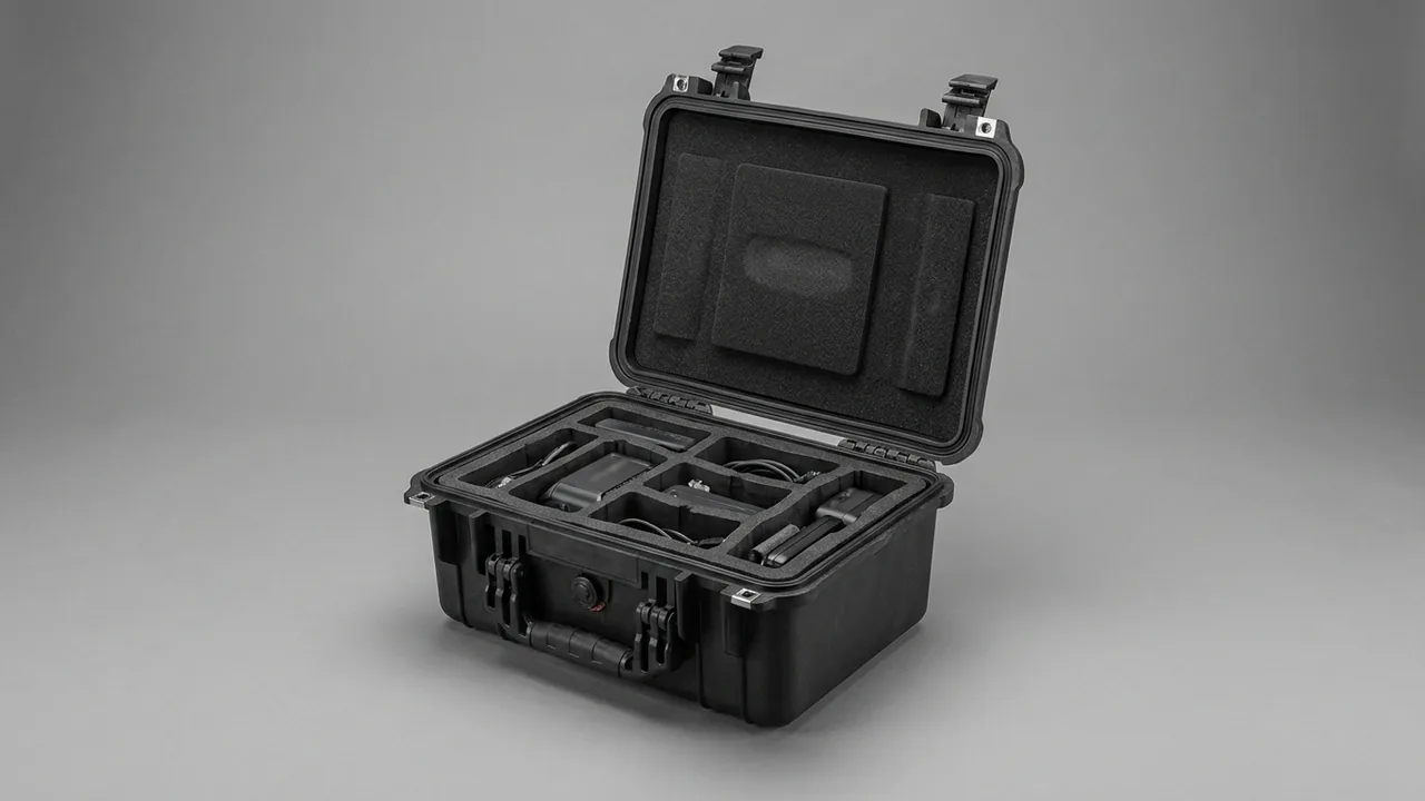
Magnet components are the hardest part of an MRI system to ship. A 1.5 T superconducting magnet typically weighs in the 3 to 5 tonne range, its wire turns operate near liquid helium temperature, and the gradient and RF coils are millimetre-tolerance structures. The goal of a magnet component case is not brute strength; it is holding shock acceleration, internal dew point and cleanliness inside the component's permitted window at the same time, because exceeding any one of the three can trigger a quench, degrade image homogeneity, or send the whole system back to the factory. The case therefore behaves like a movable precision environmental chamber: a low-conductivity isolation liner attenuates road shock, a drying and temperature-stabilising system suppresses condensation, and non-ferromagnetic hardware plus clean packaging isolate ferromagnetic contamination. This article works through superconducting magnets, gradient coils, cryogen system parts and RF coils, and gives executable answers for structure, inserts, testing and acceptance.
Magnet components are usually received in three separate legs, by the magnet manufacturer, the system integrator and the hospital. The chain includes ocean containers and also the final hundred metres of lift and corridor. Most field complaints trace back not to installation but to that invisible leg. The value of this article is that it translates failure mechanisms into quantitative case and packaging requirements, and into a checklist that can be written directly into a procurement technical agreement.
Contents
- Why Magnet Component Shipping Is the Fragile Link in Medical Imaging Supply Chains
- Three Dominant Failure Mechanisms in Superconducting Magnet Assemblies
- Gradient and RF Coils: Deformation Sensitivity and Structural Brittleness
- Cryogen System Parts and Cold Heads: Low-Temperature Shipping Requirements
- Severe Vibration Isolation: Transmissibility Curves and Dual-Layer Floating Liners
- Constant Temperature and Dew Point Control: From Desiccant to Data Logging
- Ferromagnetic Contamination Control and Clean Transfer Discipline
- Low-Outgassing Materials and Cleanroom Compatibility
- Case and Rigging Design for Constrained Hospital Installation Routes
- Inserts and Restraint: Customising to Component Geometry
- Test and Standard Basis: MIL-STD-810H, ISTA and GB/T 4857
- Unpacking, Re-Seating and Installation Handover Sequence
- Selection Checklist and Three Common Misconceptions
- Frequently Asked Questions (FAQ)
- Conclusion and Related Reading
Why Magnet Component Shipping Is the Fragile Link in Medical Imaging Supply Chains
An MRI system is not one shipment. It is a group of parts that must arrive inside the same delivery window: the magnet itself, gradient coils, RF coils, the spectrometer cabinet, the cold head and helium compressor, and water cooling skids. They often leave from different suppliers by different modes. The magnet travels on a heavy flatbed or in a frame container, while gradient and RF coils fly or move as less-than-truckload freight. When arrival schedules drift apart, the hospital equipment room simply sits empty, and every day of idle shielded room and HVAC modification keeps accruing cost.
The fragility concentrates in three places. The first is mode transfer, when freight moves from an ocean container onto an inland truck and then onto a crane. Every transfer is a potential drop or impact. The second is the final hundred metres, the lift car, the doorway, the corridor corner and the ramp, which are often the tightest and roughest part of the entire chain. The third is uncontrolled temporary storage, since equipment frequently arrives before the equipment room is finished and the magnet case may sit for weeks in a construction area or a temporary warehouse, where continuous humidity and cleanliness control matters more than short-haul transport does.
Field experience shows that a meaningful share of post-delivery anomalies in medical imaging equipment can be traced to transport and storage rather than manufacturing defects: a damaged vacuum jacket raising helium boil-off, micro-cracking in gradient coil resin, oxidised RF coil connectors, or standing condensation inside the case. What these share is that they are not necessarily visible on arrival. They appear after the first scan or after weeks of operation, as artefacts, homogeneity failures, or frequent helium top-ups. The real purpose of a magnet component case is therefore not merely to deliver the goods but to ensure the component is still in the physical state it left the factory in at the moment of unpacking. For a component with irreversible damage modes, packaging cost and return-to-factory cost usually differ by two orders of magnitude, which is exactly the line item procurement teams most often underrate.
Three Dominant Failure Mechanisms in Superconducting Magnet Assemblies
Packaging parameters can only be set once the failure mechanisms are understood. Superconducting magnet failures fall into three groups.
Mechanical disturbance triggering a quench. Superconducting wire turns are held by epoxy impregnation and banding, and small clearances remain between turns. When external shock makes turns move relative to each other, local friction generates heat, breaking the critical conditions for the superconducting state. Heat then propagates along the conductor and a quench begins. Once a quench occurs, the stored magnetic energy converts to heat almost instantly, a large volume of liquid helium boils off, and re-energising takes days under specialist conditions. This is the single event a magnet case exists to prevent.
Fatigue damage in the cold mass suspension. The cold mass hangs inside the vacuum vessel on a small number of low-conductivity support rods, designed for self-weight plus transport loads with a limited safety factor, and usually made of glass-reinforced epoxy. Repeated bending stress creates micro-cracks whose consequence is not immediate fracture but a degraded thermal path: helium boil-off creeps up from the factory figure and the hospital keeps paying for extra top-ups for years.
Ferromagnetic contamination and field artefacts. A superconducting magnet still carries field during shipping, and some models ship already energised. Iron filings, carbon steel swarf and flaked zinc plating, once drawn into the bore or onto the cryostat skin, can produce local field distortion in the imaging volume, showing up as dark bands or geometric distortion. Contamination of this kind is extremely hard to remove on site.
| Component | Dominant risk | Sensitive quantity | Packaging direction |
|---|---|---|---|
| --- | --- | --- | --- |
| Superconducting magnet body | Quench, support rod fatigue | Shock acceleration, tilt angle | Low-conductivity dual-layer isolation, attitude and tilt locking |
| Cryostat outer shell | Vacuum jacket damage, surface scoring | Local pressure, point contact | Area support instead of point support, soft facing plates |
| Cold head and helium compressor | Oil migration, tube deformation | Attitude, displacement | Factory attitude fixed, port blanks, dry nitrogen blanket |
| Gradient coil | Resin cracking, dimensional drift | Torsion and bending stress | Rigid base cradle, torsion restraint, no stacking |
| RF coil | Connector oxidation, dielectric moisture | Relative humidity, dew point | Dry packaging, individually sealed connectors |
One point deserves emphasis: magnet vendors issue transport limits as a manual delivered with the equipment, and the packaging plan must follow that manual rather than a generic packaging standard. In industry experience, most magnet models call for transport shock to be held within sub-g acceleration pulses lasting a few milliseconds, and tilt is usually limited to roughly 30 degrees, with the exact figures depending on model and suspension design.
Gradient and RF Coils: Deformation Sensitivity and Structural Brittleness
A gradient coil is a set of copper windings cast as a single epoxy body that also contains shielding layers and cooling channels. Its manufacturing precision directly sets the spatial linearity of the image, so dimensional tolerances are usually expressed in fractions of a millimetre. Cured epoxy is strong in compression but limited in bending and impact, and it fails by brittle cracking rather than plastic yield. Once cracked, the coil may still pass electrical tests while shedding resin debris into the bore, and the cooling channels may slowly weep.
Two packaging rules follow. The first is no stacking. A gradient coil cylinder carries its own weight without trouble, but when another heavy item rests on it, local pressure quickly exceeds the allowable resin stress, so the case needs a dedicated tier and a rigid divider. The second is torsion restraint. If the two ends are clamped while the middle is unsupported, bending vibration during transport applies repeated shear at the resin-to-copper interface, so the liner should provide full-length conformal support rather than two-point support.
RF coils vary widely. A body coil resembles a gradient coil structurally, while surface and head coils are light thin-wall assemblies, often with ABS or glass-reinforced composite covers that resist crushing poorly. Their real enemy is moisture: connectors, tuning capacitors and PIN diode circuits that take on water drift in tuning and lose signal-to-noise ratio. RF coils are best packed in individual dry barriers, each in its own foil laminate bag with desiccant and then into a segregated case compartment, with the case itself controlling day-night temperature swings as described in our guide to wide temperature range protective cases, so that repeated condensation inside the bags cannot occur.
Cryogen System Parts and Cold Heads: Low-Temperature Shipping Requirements
Cryogen system parts include the cold head, helium compressor, flexible helium lines, level probes, quench lines and relief valve assemblies. The shipping difficulty is not mass but internal state.
A cold head is a precision reciprocating machine with pistons and clearance seals. It must remain in the attitude specified by the manufacturer during transport. Laid flat at random, lubricant migrates under gravity into the working clearance, making the cold head hard to start or reducing its cooling capacity, and this damage is invisible to a static inspection. Pack it on a conformal cradle with positive stops that hold attitude deviation inside the permitted range, and keep a tilt indicator label on the outside.
A helium compressor is charged with high-pressure helium. All line connections need plugs plus protective wrap so that foreign matter cannot enter. Compressors are heavy, so the case floor must be stiff enough that lifting does not flex it and let the machine shift. Flexible helium lines must never be bent to a small radius; the bend radius must not fall below the manufacturer's figure, and the lines should not cross or be pinched against hard items in the case.
Quench lines and relief valve assemblies form part of a pressure boundary, and their sealing faces and setting mechanisms are easily bruised in transit. Cases for these items should follow pressure-component thinking; see our notes on restraint and marking practice for pressure vessel component cases, using compartmented positioning, upward-facing ports, and blind plates plus dust caps. Parts that involve a vacuum jacket also need protection from point contact on the shell: any sharp corner, bolt head or strap buckle can become a stress raiser and destroy the vacuum. For the wider logic of shipping deep-cold hardware, see vacuum insulation protection for cryogenic tank component cases.
Severe Vibration Isolation: Transmissibility Curves and Dual-Layer Floating Liners
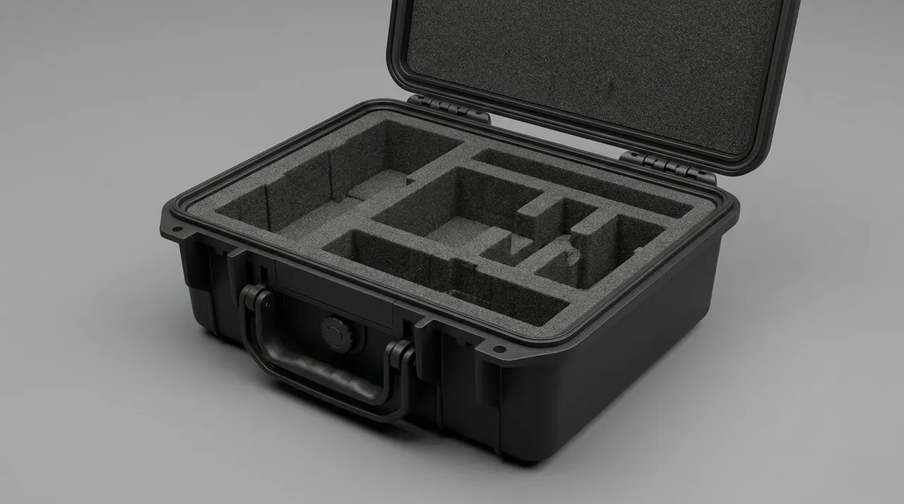
Magnet components demand far more vibration isolation than ordinary precision instruments. The design logic is reduce the input, then dissipate energy, then limit displacement.
Reducing the input depends on choosing the isolation frequency. For single-degree-of-freedom isolation, the natural frequency of the isolation system should sit at roughly one third of the excitation frequency or lower to achieve useful attenuation in the isolation region. Road transport concentrates its excitation energy at low frequency, so soft support with a low natural frequency is better at small accelerations with large displacement, at the cost of static sag and attitude control. The common compromise is a dual-layer arrangement: an inner layer of low-density closed-cell foam handles high frequency and small amplitude, while an outer layer of high-density EVA or polyurethane limits displacement and holds attitude.
Dissipating energy depends on damping. Open-cell foam damps better than closed-cell foam but carries higher moisture and outgassing risk. Closed-cell polyethylene and ethylene vinyl acetate offer low outgassing and low moisture uptake, which suits magnet rooms and clean environments. Cast polyurethane liners can be fully conformal for irregular cavities, but the cured part must be confirmed free of migratable amine residues.
Limiting displacement is the job of stops. Once the case is lifted or cornered, inertia can drive the floating component into the case wall. The remedy is a preload between liner and case plus corner displacement blocks, so that the liner floats freely under normal vibration while the blocks take over the load beyond the design limit. The block material should be softer than the case wall so it cannot damage the case in the opposite direction.
Several details are routinely missed. The case itself must be stiff enough, otherwise a soft liner inside a soft case turns the whole assembly into one low-stiffness spring that amplifies displacement. The liner-to-component interface should be area support rather than point support, with thin aluminium or rigid PVC spreader plates. Lifting and tipping are impact events too, so the case should carry centre-of-gravity and lifting-point markings, and side tipping without liner support must be prohibited. For broader material and structure combinations, see cushion liner and case structure design.
Constant Temperature and Dew Point Control: From Desiccant to Data Logging
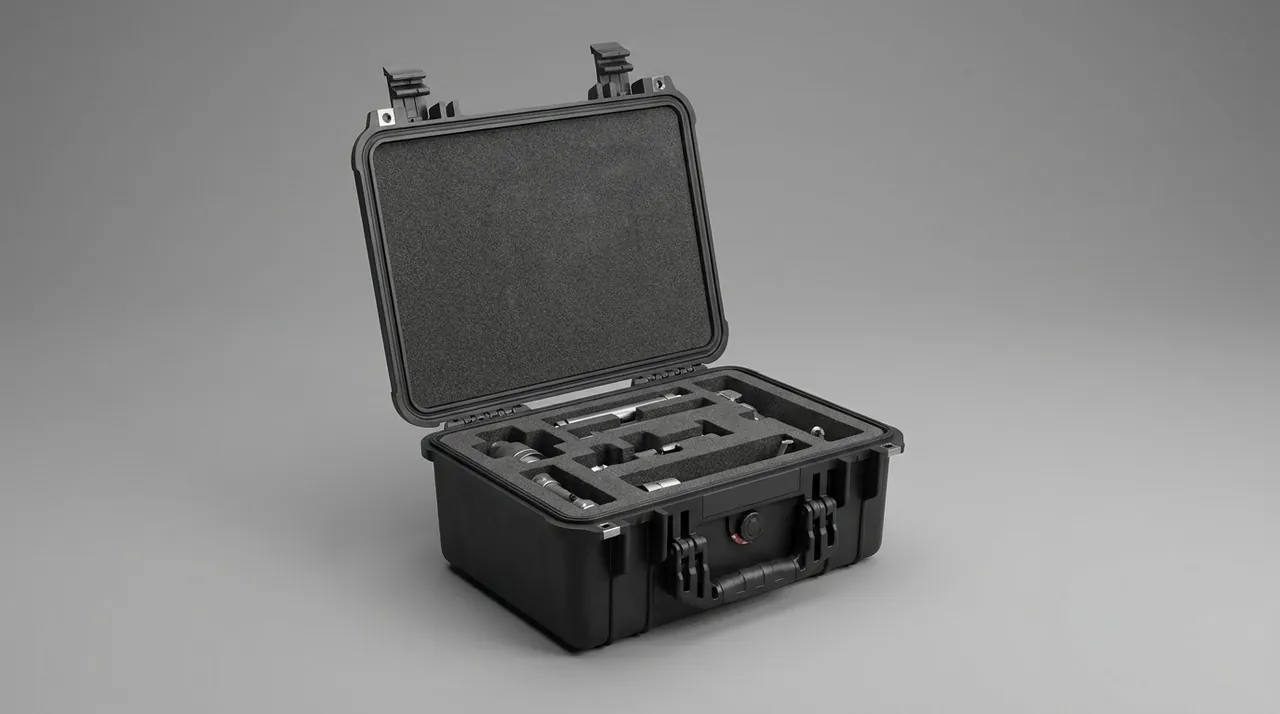
Temperature risk for magnet components shows up in three ways. First, thermal shock: a component moving from a cold store or a winter apron straight into a warm equipment room develops a large gradient, and mismatched thermal expansion between glass-reinforced epoxy and metal creates internal stress. Second, condensation: when the component surface temperature falls below the case air dew point, a water film forms on electrical connectors, optical encoders and vacuum shell coatings. Third, sustained high temperature: a closed container in summer can far exceed ambient, challenging the upper limit of some electronic modules.
Control measures rank as follows.
- Reduce the water content of the case air. Use molecular sieve or silica gel, sized from the free volume and expected storage duration with a safety margin. Bag the desiccant in breathable sachets and secure it so it cannot pile against the component in transit.
- Raise the case sealing class. Gasket geometry, material and compression set govern the moisture ingress rate; see gasket material selection and compression design. Magnet component cases are normally designed and physically verified to IP67 under GB/T 4208, which corresponds to IEC 60529.
- Fit a pressure equalisation valve. A well-sealed case develops a pressure differential in air freight or high-altitude road transport, which makes opening difficult and can damage the seal. Use a hydrophobic breather valve; see selection and installation of pressure equalisation valves.
- Log temperature and humidity. Place the logger at a representative point, usually near the upper surface of the component, with a sampling interval able to capture the day-night cycle. Data must be exportable and archivable immediately on opening. The log is the only effective evidence chain in an acceptance dispute.
- Use phase change cooling only when justified. Phase change material smooths short high-temperature excursions but adds significant case mass, which must be weighed against existing lifting limits.
Common practice holds the dew point inside a magnet component case below minus 20 degrees Celsius and applies an external humidity indicator card so the state can be judged before the case is opened. Note that desiccant has a finite capacity, so long sea passages or extended storage require scheduled replacement, and the plan should state the replacement intervals and who owns that task.
Ferromagnetic Contamination Control and Clean Transfer Discipline
The sensitivity of magnet components to ferromagnetic contamination means the case must be designed for clean, non-magnetic service, not only for impact.
Prohibited structural hardware: carbon steel bolts and self-tapping screws, zinc-plated washers, plain steel strapping, steel rivets, iron lifting eyes. Once these shed particles in handling, they can be attracted to the magnet or carried into the bore by air movement, and later removal is extremely costly. Specify 304 or 316 stainless steel, 5052 aluminium, brass, nylon and polycarbonate. Fasteners should be stainless with an anti-galling treatment so they do not generate metal debris when removed.
Prohibited packaging consumables: timber crates stapled with ferrous staples, galvanised steel banding, plain wire, and label inks containing metallic pigment. Prefer plywood crates with heat treatment or fumigation to satisfy wood packaging requirements, and ban staples entirely.
Transfer discipline starts at the vehicle standing point rather than at the equipment room door. Measures include laying clean transition mats, staging tools and fixtures on a tray and checking them for magnetism, banning angle grinders and cutting work on site, and banning ferrous tool bags near the magnet room. With regard to people, anyone carrying a cardiac pacemaker or implanted electronic device must not enter the magnet exclusion zone, and oxygen cylinders, key rings and watches must be deposited according to site rules.
| Stage | Common contamination source | Countermeasure |
|---|---|---|
| --- | --- | --- |
| Case manufacturing | Carbon steel fasteners, plated parts | Replace all with stainless or non-metallic items |
| Packing and closing | Steel banding, wire, staples | Use nylon or PET strapping, plywood crates |
| Rigging | Wire rope burrs, hook wear debris | Synthetic slings with corner protectors |
| On-site unpacking | Carton dust, tool swarf | Zoned unpacking, clean as you go, magnetic check |
| Temporary storage | Floor swarf, wind-blown grit | Dust covers and clean mats, hardened storage area |
Low-Outgassing Materials and Cleanroom Compatibility
Air cleanliness in the magnet room and equipment room is usually managed against the ISO 14644 classification concept, and some hospitals impose temporary particulate controls during installation. Once materials inside the case release condensable organics, they form a molecular film on the cold cryostat skin, lenses and optical measurement surfaces, and that film is very difficult to remove.
Screen materials against the total mass loss and collected volatile condensable materials concepts of ASTM E595, and prefer these classes: closed-cell polyethylene foam, EVA foam, polyimide film, aluminium foil laminate barrier film, and cross-linked polyethylene bags. Avoid sulphur- or halogen-bearing rubber goods, ordinary flexible PVC sheet with migrating plasticiser, screen-printed markings based on xylene or toluene solvents, and uncured silicone sealant that keeps outgassing under vacuum or at low temperature.
Labels and markings are also outgassing sources, so use low-outgassing synthetic paper with water-based ink, or engrave the marking directly into an aluminium plate. Where a component needs both stricter cleanliness and vibration isolation, see high-cleanliness vibration-isolated packaging for satellite payload component cases; its layered packaging and clean unpacking sequence applies equally well to magnet hardware.
Case and Rigging Design for Constrained Hospital Installation Routes
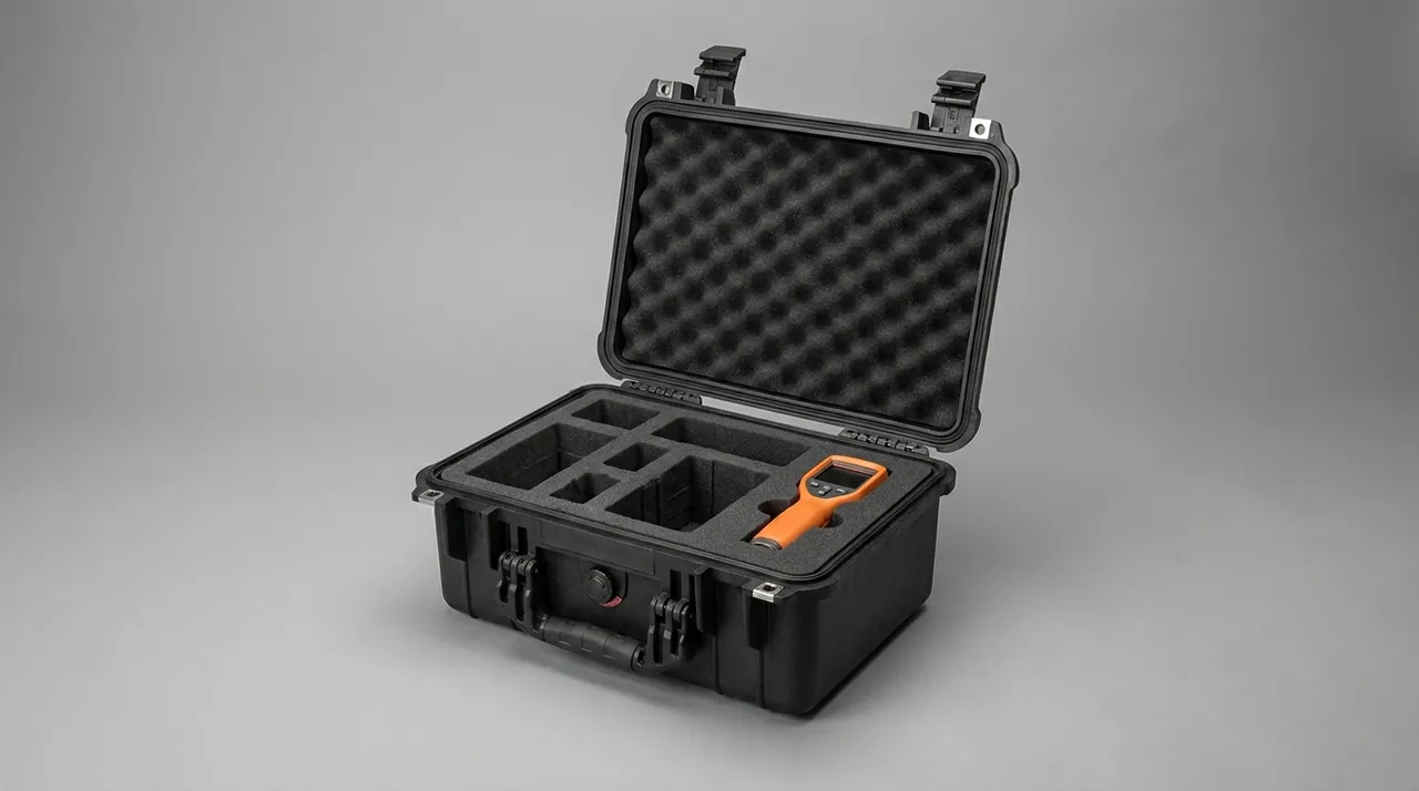
The final destination of a magnet component case is a hospital, and hospital access conditions are frequently overlooked during equipment selection. Typical bottlenecks include a lift car whose door width or depth is insufficient, a right-angle turn in the corridor outside the equipment room, a floor loading limit, a ramp or step at the entrance, and a fixed shielded doorway. These conditions must be measured before the case is designed, not discovered on delivery day.
Pre-survey checklist: measure net width, net height, turning radius, floor loading and ramp gradient along the entire route from the vehicle standing point to the equipment room; confirm the lift car's internal dimensions and rated load; confirm whether anything overhead (canopy, catenary, pipework) obstructs the lifting point. The measurements should be issued as a written record and used as the hard envelope for case dimensions.
Design responses: when the route's net width is smaller than the largest component outline, the case can use a removable lid and removable side panels so the component can be lifted straight out on slings while still supported, avoiding a second handling cycle. Keep the case footprint a regular cuboid and avoid protrusions. Provide universal lifting eyes at the four corners, positioned symmetrically about the centre of gravity, with a design load factor on the eye-to-case connection of at least 4:1. Add forklift pockets in the base and engrave the centre-of-gravity line and lifting points.
Rigging and transfer: use synthetic slings rather than wire rope, with corner protectors to stop edge cutting. Sites usually need two kinds of equipment working together, a hydraulic lift table for horizontal transition and a small mobile crane or forklift for vertical lift. All rigging work should run under a site permit system with the area cordoned off. After unpacking, move the component on a dedicated transfer trolley with conformal support rather than pushing it on a timber pallet. For the reliability of hinges, latches and seals under repeated opening, see hinge, latch and seal structure design for toolboxes.
Inserts and Restraint: Customising to Component Geometry
The insert is the real functional part of a magnet component case. The three mainstream options have different boundaries.
| Option | Best fit | Advantages | Watch points |
|---|---|---|---|
| --- | --- | --- | --- |
| Cast polyurethane | Irregular cavities, single design at volume | Fully conformal, continuous structure, moulded locating slots | Confirm cure residue and outgassing, high tooling cost |
| CNC-machined EVA | Small to medium batches, regular shapes | Short lead time, fast iteration, layered assembly | Laminate joints must be compressed, density sized to load |
| Hybrid foam plus aluminium frame | Heavy loads, long routes | Stable attitude, controllable displacement | Insulate frame from case to avoid metal-to-metal contact |
The quantitative inputs for an insert design include at minimum component mass and centre of gravity, allowable acceleration, allowable tilt, number of assembly cycles and the tools available on site. The outputs should cover support area distribution, preload, displacement clearance, extraction and lifting path, and an assembly sequence drawing. For high-precision components that must be re-seated on site, leave clearance for locating pins and angular datums in the liner so that re-seating does not become trial and error.
Do not restrain components by tightening wire rope or plastic ties directly onto them. The liner should provide location, with ties as a secondary safety only, and always with a soft pad between tie and component. Lock all fasteners against loosening and inspect for displacement marks after transport. Where components are tracked by serial number, fit a document pocket holding the packing list, liner drawing, inspection records and re-seating instructions. For how insert verification and acceptance are judged, see custom insert acceptance and AQL sampling.
Test and Standard Basis: MIL-STD-810H, ISTA and GB/T 4857
Verification of a magnet component case must leave a traceable record. Choose standards using a three-step logic of transport mode, then test item, then acceptance criterion. The table below lists commonly used references and their scope.
| Standard or document | Coverage | Notes |
|---|---|---|
| --- | --- | --- |
| GB/T 4857 series | Drop, stacking, random vibration, shock | Baseline domestic methods, combine according to transport legs |
| ASTM D4169 | Distribution cycle assurance | Often cited for air plus road combinations |
| ISTA 3A / 3E | Parcel and unitised transport tests | Applies to air unitised or LTL scenarios |
| MIL-STD-810H | Vibration, shock, temperature, humidity methods | Used as an environmental test method reference only, not a military certification |
| GB/T 4208 / IEC 60529 | Enclosure ingress protection | Used to confirm IP67 sealing |
| GB/T 191, GB/T 13384 | Packaging markings and general rules for mechanical and electrical products | Marking, stacking limits, centre of gravity and lifting points |
| GB/T 10125 | Salt spray testing | Corrosion verification for sea freight or coastal storage |
| UL94 | Flammability rating for plastic materials | Self-assessment of foam and plastic parts |
| ISO 14644 series | Cleanroom classification | Basis for clean transfer and packaging area control |
One warning is important: vibration testing for a magnet component case cannot simply reuse an electronics random vibration spectrum. Magnet risk concentrates in two regimes, low-frequency large-displacement motion and short high-acceleration pulses, so the test plan should include both a low-frequency large-displacement vibration item and a drop or half-sine shock item, with accelerometers placed at critical points on the component. Pass or fail on the test alone is not sufficient evidence; recorded values are. Every test should document sensor range, sampling rate and mounting position, otherwise the data cannot support a dispute decision.
Unpacking, Re-Seating and Installation Handover Sequence
Unpacking is a sequenced technical operation, not a matter of cutting straps. Run the following steps and sign each one off.
- Read the environment record first. Export the temperature and humidity logger data before opening, and confirm no excursion beyond limits; check whether the external humidity indicator card and tilt indicator have changed colour.
- Inspect the case. Record dents, deformation and abnormal gasket compression on the exterior with photographs; confirm lifting points and latches are not deformed.
- Open and document. Open in the sequence drawing, photograph before separating liner from component, and record the actual position of the component in the liner to compare against the as-shipped condition.
- Check for ferromagnetic contamination. Using non-magnetic tools and clean wipes, inspect the outer surfaces, focusing on bore edges, flange faces and packaging interlayers for metal particles.
- Verify the component. Against the vendor manual, check appearance, labels, port blanks and connector caps, confirm no parts are missing, and for cryogen-related parts check whether boil-off or level readings sit inside the factory range.
- Re-seat and store. If the equipment room is not ready, move the component into a temperature and humidity controlled holding area and keep the liner and case for a second transfer; never leave a heavy component lying flat without support for long periods.
- Hand over to installation. File the transport record, unpacking record and vendor installation report in a single equipment file as the basis for later warranty and performance acceptance.
The most important principle in this sequence is document before you disturb. Any anomaly should be recorded before unpacking. Once a component leaves its liner, attributing liability becomes extremely difficult.
Selection Checklist and Three Common Misconceptions
Use the checklist below item by item with the supplier; a missing line means the plan is not yet closed.
| Check item | What to confirm |
|---|---|
| --- | --- |
| Component list and centre of gravity | Mass, envelope, centre of gravity, allowable tilt for each item |
| Transport route | Modes, number of transfers, net clearance and floor loading on the final leg |
| Environmental window | Allowable temperature range, case dew point limit, logger configuration |
| Cleanliness requirements | Cleanliness class, low-outgassing material list, ferrous hardware ban list |
| Structure | Maximum case dimensions, lifting points and forklift pockets, removable panels |
| Insert | Material and density, support distribution, displacement clearance, sequence |
| Verification | Standards and items, sensor placement, report format |
| Documentation | Packing list, liner drawing, logger data, acceptance criteria |
Misconception one: treating drop resistance as vibration isolation. Drop resistance addresses a low-frequency, large-displacement accident. The daily threat to magnet components is cumulative damage from long, low-amplitude vibration, and the remedies differ. A case validated only by drop testing may still let support rods fatigue on a long road leg.
Misconception two: substituting an ordinary dry box for a temperature-stabilised drying case. Ordinary dry boxes are sealed and sized for electronic components and cannot cope with day-night temperature swings across climate zones or with extended storage. A sealed box without a pressure equalisation valve may not even open normally after air freight.
Misconception three: ignoring the final hundred metres. A large share of damage happens during short internal movements inside the hospital, and that leg usually has no constraints in the packaging plan at all. Adding net width, turning geometry and floor loading as design inputs is the lowest-cost improvement available.
Frequently Asked Questions (FAQ)
Q: Do MRI magnet component cases really need dew point control, or will an ordinary dry box do?
A: They need it, and dew point is often more critical than temperature. What decides whether liquid water forms is the difference between the component surface temperature and the case air dew point. After storage in a cold area, a component entering a warm humid equipment room can have a surface temperature more than ten degrees below the surrounding dew point, and the water film forms preferentially at electrical connectors, flange faces and coating defects. Ordinary dry boxes rely on static sealing plus desiccant, with no pressure equalisation valve, so air freight or high-altitude road transport creates a differential that flattens the gasket or prevents opening. Their desiccant charge is also sized for small electronics and is long since saturated after several weeks at sea. The correct approach is to calculate moisture ingress leg by leg, fit enough molecular sieve or silica gel with a defined replacement schedule, hold the case dew point below minus 20 degrees Celsius, and log temperature and humidity throughout. Only then can data either prove or exclude an environmental cause when an anomaly appears at unpacking.
Q: What vibration acceleration is permitted when shipping a superconducting magnet?
A: The figure comes from the magnet vendor for each model and suspension design, and the transport manual governs. There is no universal number. Engineering-wise, the limit originates in three constraints acting together: the fatigue life of the cold mass support rods, the relative displacement threshold of the wire turns under shock, and the tolerance of the vacuum jacket to shell deformation. These jointly define an acceleration limit paired with a pulse width. In industry experience, most models are considerably stricter about short shock pulses than about continuous vibration, because a single high-acceleration pulse is more likely to displace wire turns. A case design therefore cannot be judged solely by passing one vibration spectrum; it must consider pothole impacts, speed bumps, handling drops and rail coupling shocks together. The practical route is to write allowable acceleration, pulse width and allowable tilt into the technical agreement at the design stage, then place accelerometers at critical points on the component during verification and compare recorded peaks against the manual limits, item by item. If a recorded peak approaches but does not exceed the limit, note it in the record anyway as a lead for later performance investigation.
Q: Why can a magnet component case not use ordinary carbon steel fasteners?
A: The core reason is that ferromagnetic contamination causes irreversible damage. A superconducting magnet often still carries field during shipping, so debris shed from carbon steel fasteners, flaking from zinc-plated washers and even grinding dust left during assembly can be drawn onto the cryostat skin or into the bore edge. Once such particles settle near the imaging volume they distort the local field, showing up as dark bands, geometric distortion or reduced signal-to-noise ratio, and they are almost impossible to remove completely on site, usually requiring disassembly or return to the factory. Beyond fasteners, crate staples, galvanised steel strapping, label inks with metallic pigment and burred wire rope are equally high risk. A workable approach is to switch all case and packing hardware to 304 or 316 stainless steel, 5052 aluminium, brass, nylon and PET strapping, use synthetic slings with protective sleeves for lifting, and require the supplier to perform a magnetic particle check inside the case before dispatch with a written record. The cost increment is small, and for a component with irreversible damage modes it is a necessary investment.
Q: What preparation do cryogen system parts need before being packed?
A: The objective is to have the component enter transport with a protected internal state. Confirm the cold head remains in the manufacturer's specified attitude so that internal lubricant does not migrate into the working clearance, pack it on a conformal cradle with positive stops, and keep a tilt indicator label visible. The helium compressor is pressurised internally, so all line connections should receive plugs and dust caps plus protective wrap to keep out foreign matter and prevent thread damage. Flexible helium lines must never be bent to a small radius; stay above the manufacturer's minimum bend radius, avoid crossing or pinching against hard items, and give them a dedicated tier or an arced cradle where possible. Level probes and quench lines form part of a pressure boundary, so position them in compartments with ports facing up and fit blind plates, following pressure component practice. For extended storage, consider a slight positive pressure of dry nitrogen plus desiccant and a humidity indicator card inside the case. List every plug and protective cap as a separate line on the packing list so that none is missed during site installation.
Q: After shipping, how do we tell whether a gradient coil has deformed?
A: Deformation is rarely visible to the eye, so work through an indirect evidence chain. First inspect appearance: look for fine cracks, whitening or shedding on the cast epoxy, especially at the coil ends, cooling channel fittings and shield layer overlaps, where stress concentrates. Second, re-measure dimensions and geometry with calibrated instruments against the factory drawing, focusing on mounting faces and hole positions for out-of-tolerance deviation; this is normally done at the system integrator or before hospital installation. Third, run functional verification: after installation, perform routine gradient linearity and eddy current compensation tests, and compare any geometric distortion or edge dark banding against the factory baseline. Fourth, trace the packaging state: check for compression marks in the liner, displaced displacement blocks and impact marks on the case exterior, which indicate whether an out-of-limit event occurred in transit. One caution: resin cracking in a gradient coil may leave electrical performance intact while continuing to shed debris, so even when tests pass, any visible shedding should be escalated and evaluated under procedure.
Q: The hospital route is narrow. How should case dimensions and rigging be planned?
A: Planning starts with measurement, not with a case drawing. Survey the entire route from the vehicle standing point to the equipment room, recording net width, net height, usable diagonal at right-angle turns, floor loading limits, ramp gradient, and the lift car internal dimensions and rated load, and confirm whether a canopy, catenary or pipework obstructs the unloading point. These figures form the hard envelope for case dimensions. Design responses include using a removable lid and removable side panels so the component can be lifted directly out on slings while still supported, avoiding a second handling cycle on the ground; keeping the outline a regular cuboid to reduce protrusions; fitting universal lifting eyes at four corners positioned symmetrically about the centre of gravity with a connection design load factor of at least 4:1; and adding forklift pockets plus engraved centre-of-gravity and lifting point markings. For rigging equipment, prefer synthetic slings with corner protectors, a small mobile crane or forklift for vertical lift, and a hydraulic lift table for horizontal transition. All rigging should be brought under the hospital permit-to-work and cordon arrangements.
Q: What customisation and documentation support can JUNZHIJIA provide?
A: As a brand of JUNZHIJIA, JUNZHIJIA builds protective case programmes to order for demanding applications such as MRI magnet components. Typical scope covers calculating insert support and displacement clearance from component mass, centre of gravity, allowable acceleration and allowable tilt; selecting foams and auxiliaries against cleanliness and outgassing requirements and supplying the material list plus in-house inspection records; designing case outline, removable structure and lifting points around the measured hospital route envelope; and configuring compartments, label positions and document pockets by component serial number. On documentation, we can work with customers to provide packing lists, liner drawings, assembly and disassembly sequence instructions, flammability self-assessment to UL94 concepts, seal class verification records, and an export format for the in-case temperature and humidity logger. Where a project must satisfy a specified test standard such as the GB/T 4857 series, ASTM D4169 or ISTA, we can coordinate third-party laboratory execution and issue the report. Wholesale, distribution and OEM/ODM cooperation models are supported, and seal kits and spare part lists can be configured per project batch. Specific terms follow the mutually agreed technical agreement and quotation.
Q: After shipping we see image homogeneity degradation. How do we separate a packaging problem from a shielded room problem?
A: Build a timeline and eliminate causes one by one. Start with the environmental record: export journey temperature, humidity and shock data and check whether any leg exceeded limits, because an excursion raises the probability of a transport cause sharply. Next check the site: RF door gasket condition, waveguide vent installation, and any new metal in the equipment room such as ceiling rails, cable trays or fire pipework. Third, check the magnet itself: compare helium level and boil-off readings against factory values, since rising boil-off points to vacuum jacket or support rod damage. Fourth, compare homogeneity results against the factory and commissioning baselines, and note whether degradation is global or local. Local dark bands suggest local field distortion or a foreign body; global degradation points to shielding, shimming or magnet state. Finally, preserve evidence, because attributing liability requires the packaging, unpacking, installation and vendor inspection records together.
Conclusion and Related Reading
A magnet component case is a transportable environmental control system. It must deliver vibration isolation, temperature-stabilised dryness, cleanliness and rigging readiness at the same time, because strength in one dimension never compensates for weakness in another. JUNZHIJIA builds custom inserts, non-ferromagnetic structures and low-outgassing packaging for superconducting magnets, gradient coils, cryogen parts and RF coils.
Related reading