

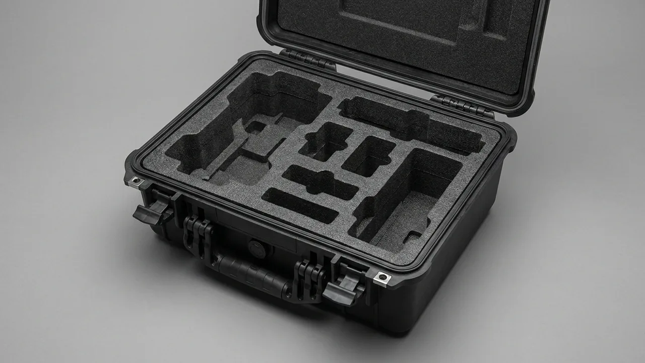
A satellite payload travels from the integration hall to the launch site, or from the spacecraft test room to an environmental laboratory, often covering only a few tens or hundreds of kilometres. That short leg effectively decides whether the payload arrives on schedule. The conclusion is unambiguous: payload modules, optical payloads, star trackers, and antenna assemblies cannot be crated using a generic valuable-instrument approach. Cleanliness, low outgassing, vibration resistance, and static control must be designed onto one drawing at the same time. Define the packing and unpacking environment in ISO 14644 cleanliness terms, screen liners and consumables against the ASTM E595 outgassing logic, verify the cushioning chain using random and sine vibration test methods, and hold particles and molecular contamination away from optical surfaces with full-time equipotential bonding and double-layer peel packaging. Only then can the payload be unpacked and used without a second cleaning cycle. Any plan that packs first and remediates later ends up back in the cleanroom.
Compared with ordinary industrial spares, the cost of rework on a satellite payload is not carried by the part itself but by the schedule behind it. One contaminated mirror may trigger re-cleaning, re-measurement, and re-calibration, and can push the spacecraft test sequence. Worse, most damage is invisible on the day of unloading. Particulate contamination only shows under dark-field or high-magnification inspection, outgassed deposits only reveal themselves after thermal vacuum testing, and micro-cracks in adhesive layers from sustained vibration only grow during mechanical testing. This article is written for payload subsystem suppliers, spacecraft prime contractors, and procurement staff. It sets out failure inventories by component class, cleanliness chain design, low-outgassing material screening, cushioning and vibration verification, the double-layer peel workflow, and acceptance clauses that can go straight into a technical agreement.
Table of Contents
- Transport Failure Modes and Protection Boundaries for Satellite Payload Components
- Cleanliness Chain Design: Packing and Unpacking in ISO 14644 Terms
- Outgassing Control and Material Screening: The ASTM E595 Logic
- Supporting, Stiffening, and Restraining the Payload Module
- Protecting Optical Payloads and Precision Optical Surfaces
- Clean, Vibration-Damped Packaging for Star Trackers and Attitude Sensors
- Interface and Coating Protection for Antenna and Microwave Assemblies
- Antistatic Packaging and ESD-Sensitive Units
- Vibration Design: Random and Sine Test Logic
- Double-Layer Peel Packaging and the Unpacking Transfer Workflow
- Temperature, Humidity, Condensation, and Pressure Equalisation
- Liner Material Selection, Cavity Design, and Customisation
- Marking, Traceability, Test Verification, and Arrival Acceptance Clauses
- FAQ
- Conclusion and Further Reading
Transport Failure Modes and Protection Boundaries for Satellite Payload Components
Collected field records group satellite payload transport damage into four directions, and they feed on each other. Contamination comes first. Particles landing on a mirror or optical window change scattering behaviour immediately, while molecular contamination deposits as a nanometre-thin film on cold optical surfaces. Neither disappears on its own. Geometry is second. Once the mounting datum of a large payload module is chipped or plastically deformed, the spacecraft interface needs on-site fitting, and fitting introduces fresh metal swarf and a fresh contamination source. Electrical damage targets electronics units and star trackers, where electrostatic discharge punctures detectors, CMOS pixels, or front-end circuits, typically surfacing only during a powered self-test. Mechanical damage appears as loosened fasteners, micro-cracked bond lines, and damaged seal grooves on corrugated horns and waveguide flanges.
All four share one time signature: a long latency, poor reproducibility, and disputed responsibility. The design objective is therefore not simply to move the hardware but to arrive in a state that can be re-measured, judged, and traced. The judgement method has to be fixed before packing. Optical surfaces are checked by dark-field inspection and wipe sampling, module datums by coordinate measuring machines or laser trackers, and electronic units by electrical self-test. The table below pairs each component class with its failure focus and matching action so that items can be checked one by one.
| Component class | Primary failure mode | Unit protection action | Fixing and support method | Process indicator (typical) |
|---|---|---|---|---|
| --- | --- | --- | --- | --- |
| Payload module body | Chipped mounting datum, plastic structural deformation | Protective pad over datums plus a recorded surface survey | Rigid base plate with original hole pattern, never suspended | Datum flatness change on re-measurement not above 0.2 mm |
| Optical payload (barrel or lens) | Particulate and molecular contamination on mirrors | Dust-free cover plus double bag with peelable inner layer | Low-outgassing support seats, primary mirror never load-bearing | No new visible particles on arrival dark-field check |
| Star tracker | Detector ESD puncture, optical head misalignment | Antistatic shielding bag plus clean inner wrap | Compartment tray restraint, baffle opening upward | Liner surface resistance of 10^4 to 10^6 ohm |
| Antenna assembly and waveguide feed | Chipped flange seal groove, sulphidised plating | Non-metallic flange cap plus clean plug | Clamps carry the body, end faces free | Flange face visually free of particles and swarf |
| Electronics units and harness | ESD puncture, connector strain | Individual antistatic bag | Pins upward in divided tray | Bonding terminal resistance as agreed in the specification |
| Precision structures and brackets | Stress distortion, coating loss | Edge and corner guards | Equally spaced multi-point support, spacing set by stiffness | Straightness not above 1 mm per metre |
Judgement principle: no visual inspection result replaces re-measurement. Measure before packing, after packing, and on arrival. The delta matters far more than the absolute figure.
Cleanliness Chain Design: Packing and Unpacking in ISO 14644 Terms
The cleanliness requirement for a satellite payload cannot be written only at the moment of unpacking. It has to be defended stage by stage across the whole chain of packing, sealing, transfer, entry into the facility, and unpacking. That is what a cleanliness chain means. ISO 14644-1 sets class limits by maximum permitted particle concentration per cubic metre, commonly written as ISO Class 5 through ISO Class 8, with the older hundred, thousand, and ten-thousand designations still used in everyday engineering conversation. For payload packaging, three locations need separate definitions: the environment where packing takes place, the state the case cavity must maintain, and the environment where unpacking takes place. Usually the unpacking environment is the strictest, because that is the one moment the hardware is genuinely exposed to air.
The practical way to build the chain is to manage an outer layer and an inner layer separately. The outer layer is the transit case itself. It carries mechanical protection, sealing, and climate resistance, and it may be handled in an ordinary workshop or even outdoors. The inner layer is the clean wrapping system that touches the payload, comprising dust-free bags, clean liners, clean support seats, and protective covers, operated only in a controlled environment. The two are joined by a peel layer, which is the double-layer structure discussed later. The benefit is straightforward. The case can be lifted, stacked, and loaded in any environment, and as long as the peel layer is intact the clean inner state is preserved.
Consumable choices shape the result just as much. Liners must not use fibre-shedding flocked material, unsealed open-cell foam, or plasticised flexible PVC. Operators wear powder-free gloves and cleanroom headwear, and do not talk, cough, or move quickly above an open case. Tools, logbooks, and label stock are wiped before entering a controlled zone. The exterior of the case is wiped and film-protected before crossing the cleanroom threshold so that outside dust is not carried in. Where class, sealing level, and work instructions must be defined together, the environment matching method described in the cleanroom-grade protective case selection guide is a useful reference.
Outgassing Control and Material Screening: The ASTM E595 Logic
In an orbital vacuum, organic molecules released by materials do not disperse and vanish. They migrate along temperature gradients and deposit on cold surfaces, forming molecular contamination that cannot be reversed by optical cleaning. Satellite programmes therefore impose low-outgassing requirements on liners, adhesives, labels, and packaging consumables. The industry screening logic comes from the ASTM E595 vacuum outgassing test method, which measures total mass loss (TML) and collected volatile condensable materials (CVCM) under defined temperature and vacuum conditions. A widely used engineering gate is TML no greater than 1.0 percent and CVCM no greater than 0.10 percent. That gate is written for materials that fly, but a packaging liner inside a sealed case releases volatiles onto the same optical surfaces, so applying the same screening logic is both reasonable and inexpensive.
The difficulty is that conventional cushioning materials sit in natural tension with low-outgassing demands. Standard EVA and PE foams cushion well and cost little, but carry a higher volatile baseline. Silicone foam stays flexible at low temperature yet may contain low-molecular-weight siloxanes, and once those migrate onto an optical surface they are extremely hard to remove. Three compromise routes work in practice. First, insert a low-outgassing barrier film between the foam and the hardware so volatiles have nowhere to deposit. Second, replace only the parts that touch the payload, such as support seats and pads, with low-outgassing compounds, while non-contact zones keep standard foam for cushioning. Third, cap the internal temperature and the rate of temperature change to reduce volatile flux per unit time. The table below gives experience-based orientation for common liner and consumable materials; final selection still depends on test reports obtained from the supplier.
| Liner or consumable | Relative outgassing baseline (experience-based) | Typical use | Caution |
|---|---|---|---|
| --- | --- | --- | --- |
| Low-outgassing closed-cell foam | Low | Support pads and restraint blocks touching hardware | Request TML and CVCM reports, watch batch drift |
| Standard closed-cell EVA or PE foam | Medium | Cradles, interlayers, void filling | Add a barrier film between foam and optical surfaces |
| Polyester or polyimide film | Low | Wrap layers and barrier layers | Avoid dust traps at creases, seal cut edges |
| Silicone foam | Medium (siloxane risk) | Low-temperature cushioning | Use cautiously near optical payloads |
| Plasticised flexible PVC | High | Not recommended for payload packaging | Plasticiser migration contaminates optics and plating |
| Flocked or unsealed open-cell material | High (also sheds) | Do not use in direct contact | Only acceptable far from hardware on outer case walls |
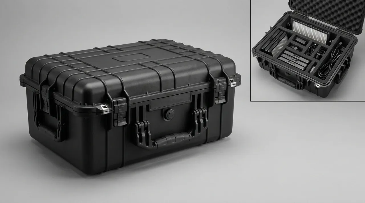
The most reliable way to decide whether a material route is acceptable is a witness-coupon trial. Place a coupon of the same material as the optical surface inside a sealed container of the intended specification together with the candidate liner, then run an accelerated soak at the highest transport temperature expected, and afterwards check the coupon for hazy deposits or a change in contact angle. This test costs very little and locks the material route down before tooling is cut. For combinations with tighter cleanliness and outgassing targets, the material zoning logic in the custom foam insert tooling guide is worth reading alongside this section.
Supporting, Stiffening, and Restraining the Payload Module
A payload module body is heavy, relatively compliant compared with the spacecraft structure, and has concentrated mounting interfaces. In transit it sees two load families: static load from its own weight and from stacking, and dynamic load from road excitation. Support distribution controls the static case, restraint plus cushioning controls the dynamic case. The first step in support design is to identify the design load path, normally the original mounting flange, the interface ring, or the lifting interface. Supports must land on those features. Optical windows, radiator surfaces, and thin-walled panels must never carry weight.
The support faces themselves need attention. Direct metal-to-metal contact between a support block and a structure produces fretting wear under vibration, generating metal powder and leaving witness marks. Support faces should therefore carry a non-metallic low-outgassing pad 5 to 10 mm thick, compressed 10 to 20 percent under static load. For lateral restraint, leave a 2 to 3 mm assembly gap between the side blocks and the structure edge and fill it with low-resilience foam. The gap prevents sustained compression at room temperature from concentrating stress, while the foam absorbs lateral impact energy. Straps restrain displacement only and are never the primary fixing. A tension that produces roughly 10 mm of deflection when pressed by hand is a reasonable target.
For modules heavier than about 100 kg, a better answer is a load-bearing base plate rigidly connected to the case, with the module bolted to the plate through its original holes and the plate connected to the outer case through distributed elastic support blocks. This creates a two-stage load path of case, elastic supports, rigid plate, and module. Dynamic load is spread over a large area before it reaches the module, which is far more effective than simply thickening the foam. Where a component needs tighter temperature or vibration control, the multi-stage suspension and thermal buffering approach described for precision component transport with temperature and vibration control transfers well to large payload module sections.
Protecting Optical Payloads and Precision Optical Surfaces
The core rule for optical payload transport fits in one sentence: keep every optical surface from touching anything, and from touching anything that can outgas. Optical surfaces include mirrors, windows, filters, and detector windows. Their shared weakness is that they suffer from both particulate and molecular contamination, and neither can be cleaned on site without risk. Three protection layers are standard. The first is the optical cover or cap supplied by the manufacturer, which stays fitted for the entire journey. The second is an inner clean wrap, using cleanroom-grade film or a bag around the whole assembly, with seams facing down and openings directed away from optical surfaces. The third is the clean cavity inside the case, where liner surfaces are treated for cleanliness and the cavity floor carries a collection groove so that trace particles generated in transit settle away from the hardware.
Orientation matters just as much. An optical payload should travel in its design load orientation, or with the optical axis vertical, as stated in the manufacturer technical conditions. Never support a barrel horizontally at two points only, because self-weight produces mid-span sag and long-duration vibration can change the spacing between lens groups. Where horizontal transport is unavoidable, fit equally spaced curved cradles along the whole barrel, line the cradle curve with clean felt or closed-cell foam, and maximise contact area. Point supports are not acceptable. Clearance between every cradle and any optical surface must be explicit, and contact is permitted only at structural rings or flanges.
Humidity is the second enemy. High humidity builds an adsorbed water layer on a mirror, which then desorbs slowly in vacuum, carrying contamination with it. Fit desiccant and a humidity indicator card, and target a relative humidity below about 40 percent for long transport legs. At the same time, avoid combining aggressive drying with static accumulation, so keep desiccant dosing conservative in the region of 20 to 40 g per cubic metre, which is enough to suppress condensation. Optical liners are shaped very differently from ordinary cushioning parts; the clean routing and edge sealing notes in the EVA foam insert custom process apply directly.
Clean, Vibration-Damped Packaging for Star Trackers and Attitude Sensors
Star trackers, sun sensors, and inertial sensors are hybrids of precision optics and precision electronics, and their inner packaging requirements are often stricter than those for large payload modules, because small size and low areal density make them easier to excite at high frequency. Four design points matter. First, pack each unit individually, using an antistatic shielding bag as the inner layer and a clean bag outside it, without evacuating to a hard vacuum so that the bag cannot press on the baffle and load the structure. Second, restrain by area contact with elastic preload rather than point clamping. Seat the unit in a compartment tray and hold the top face with a light elastic pad to remove vertical play. Third, point baffles, barrel apertures, and similar openings upward or sideways, never downward, so particles cannot fall into the optical path. Fourth, give every unit its own compartment number and position number so that arrival checking is done against the packing list.
Clamping force must be quantified. Excessive preload leaves residual stress in the mounting ears or structural ring and produces micro-deformation after long storage, while insufficient preload allows relative motion under high-frequency vibration that wears through surface coatings. A practical method is to fit pressure-sensitive paper, or to place white paper on the pad, press once, and read the witness width, so that feel becomes data. Partition walls between units should be at least 10 mm thick and must carry load independently. The clamping force of one unit must never be transmitted to its neighbour through a shared divider.
One easily overlooked detail is residual magnetism. Some sensors are sensitive to it, and fasteners, wire in labels, or nearby permanent-magnet lifting gear can all matter. Avoid magnetic locating clips in the packaging, forbid permanent-magnet lifting devices, and keep magnetic items well separated from sensors. Where moisture control is also required, fit low-dust desiccant with a small humidity indicator card and handle the internal-to-external pressure differential using the equalisation approach described later.
Interface and Coating Protection for Antenna and Microwave Assemblies
The most vulnerable part of an antenna or microwave assembly in transit is not the body but the interfaces: flange seal grooves, connector pins, threaded holes, and plated surfaces. Silver plating on waveguides and feeds sulphidises to black in sulphur-bearing air, raising surface resistance and increasing insertion loss. Once a flange seal groove is dented, even correct seal compression cannot produce a continuous sealing line, and there is no way to repair it on site. The protection logic is to seal inside and shield outside. Fit a non-metallic protective cap over the flange face first, in nylon or PEEK, so that the cap itself cannot become a metal impact source. Plug the waveguide aperture with a clean plug that will not shed, and keep the mating face smooth enough to avoid generating particles.
Fixing follows the principle that clamps carry the body and end faces stay free. The flange face is the weakest sealing interface and must never rest on the case floor or a support beam. Clamp the waveguide body or a structural flange instead. Flexible waveguide sections must not be bent below the manufacturer minimum radius, with ten times the outer dimension a common experience-based figure, and should be coiled or laid on a large-radius curved cradle so that permanent kinks do not form. Relative movement between parts must be eliminated, because small reciprocating friction between adjacent metal parts polishes bright marks into platings, and these are the most common deduction in visual acceptance.
For feeds with high cleanliness requirements, the case interior can be filled with dry nitrogen or fitted with low-dust desiccant, and operators should wear powder-free gloves rather than touching plating bare-handed. Arrival inspection is best done in the order of flange first, bore second, electrical performance last, so that a failed electrical test can be attributed correctly rather than being blamed on transit by default. Material selection, compression values, and compression set limits for seals are tabulated in the seal material selection comparison.
Antistatic Packaging and ESD-Sensitive Units
The electrostatic sensitivity of satellite electronics is usually classified under the human body model and the charged device model, and many devices tolerate only a few hundred volts under HBM, while a person walking on a dry floor or removing a synthetic jacket can easily generate several thousand volts. The transport objective is equipotential bonding throughout. Wrap each unit in a metallised shielding bag, place it in a conductive foam compartment tray, bond the tray to the case bonding terminal through conductive gasket or metal braid, and bond the whole case to the workstation earth bar before unpacking begins.
Humidity is the second variable in static control. Below about 30 percent relative humidity, synthetic liners and plastic case surfaces readily accumulate charge, so long-term storage and transport should be held between roughly 30 and 60 percent relative humidity with a humidity indicator card in the case. Here a frequently missed conflict appears. Static control wants moderate moisture, while optics and vacuum cleanliness want dryness. Where components with different requirements travel in one case, compartment them and set separate humidity strategies instead of picking a single compromise value. For antistatic liners, choose conductive EVA or PE with a surface resistance of 10^4 to 10^6 ohm, which cushions without acting as an insulator. Mark the case to GB/T 191 with the electrostatic-sensitive and keep-dry pictograms.
Unpacking is the weakest moment in the whole chain. The disciplined sequence is: bond the case to the workstation earth first; then remove units from their shielding bags at a static-protected workstation with a grounded mat and a verified wrist strap; do not open the bag immediately but let it sit on the bench to equalise, then cut from the end furthest from the device pins; and transfer devices in conductive tote boxes rather than placing them on ordinary plastic bags or clothing. The full antistatic packaging system is set out in the ESD shielding case solution, whose foam resistance bands and bonding methods apply equally to satellite units.
Vibration Design: Random and Sine Test Logic
Cushioning exists to bring excessive acceleration down to a level the hardware can survive. Two routes run in parallel: energy absorption through foam compression, and structural two-stage suspension. For large payload modules, simply adding more foam is ineffective, because compression across a large area is uneven and hard spots form. A better arrangement puts distributed elastic support blocks between the case and the load-bearing plate, spreading load across many points, and then covers them with a continuous foam layer to give point support plus area cushioning. For small precision units, a lighter approach works better: a compartment tray with an elastic top clamp, using structural restraint instead of a thick cushion layer, so that a few kilograms of hardware do not require a heavy case.
On material parameters, satellite components commonly use closed-cell EVA or PE foam at 45 to 70 kg per cubic metre, compressed 10 to 20 percent under static load. Softer material takes a permanent set under sustained vibration and the support fails, while harder material absorbs almost nothing. Drop verification is scaled by mass: light optical items may be checked at 60 to 80 cm on a corner or edge, heavy modules at 40 to 50 cm. These are engineering experience values and should be confirmed by test. Low-frequency resonance also needs attention. When the natural frequency of the foam and hardware system falls in the 5 to 20 Hz band and approaches the dominant frequency of the vehicle, response can amplify several-fold, so foam density, damping layers, or support spacing must be adjusted to push the natural frequency away from the excitation band.
Random and sine vibration serve different purposes and cannot substitute for each other. Random vibration describes broadband energy distribution by power spectral density and is closer to real road and cargo aircraft environments. Sine vibration excites one band at a time by fixed frequency or sweep, which is how structural resonances and fastener failures are located. The table below pairs both with the usual accompanying tests.
| Test item | Reference method | Verification intent | Parameters (typical) | Judgement |
|---|---|---|---|---|
| --- | --- | --- | --- | --- |
| Random vibration | GB/T 4857.23 or ASTM D4169 | Simulate broadband transport energy | One road spectrum and one heavy-haul spectrum, 30 to 60 min per axis | No displacement, no strap release, no liner collapse |
| Sine sweep | MIL-STD-810H Method 514 logic (method reference only, not a military certification) | Locate resonances and weak structure | 5 to 100 Hz logarithmic sweep at about 1 octave per minute | No abnormal noise at resonance, no loosened fasteners |
| Drop | GB/T 4857.5 or ISTA 2A | Handling shock | Corner, edge, and face once each | No through-thickness liner collapse |
| Stacking | GB/T 4857.3 | Storage and load stacking | Load converted from stack height, held 24 h | No permanent case wall deformation, liner recovers |
| Thermal shock | MIL-STD-810H Method 503 logic | Seal and adhesive ageing from temperature swings | High and low cycles with controlled transfer time | No gasket cracking, no foam embrittlement |
| Damp heat | MIL-STD-810H Method 507 logic | Humid environment tolerance | High-temperature high-humidity cycling | No condensation or mould inside the case |
The most common mistake is testing only at case level. Split verification into two lines. Case level proves the shell, latches, gaskets, and liner survive extreme load. Component level, performed before the liner is frozen, uses a dummy load or a scrapped unit to check restraint reliability, permanent foam set, and strap loading. Test sequence selection should follow the execution logic in the ISTA transport testing procedure and the ASTM D4169 distribution cycle design.
Double-Layer Peel Packaging and the Unpacking Transfer Workflow
Double-layer peel packaging is standard practice for clean transport of satellite payloads. Its logic is to leave contamination on the outer layer and cleanliness on the inner layer, using successive peeling to complete the environmental transition. The construction is simple: the payload first receives an inner clean wrap of dust-free bag, clean liner, and protective cover; an outer protective bag or soft cover goes over that; and a transition layer, such as a clean woven sleeve or antistatic cover, may sit between them. The finished wrap is then secured in the clean cavity of the transit case.
The workflow has four nodes. Node one is packing inside the cleanroom, confirming the inner wrap is intact and recording its cleanliness state. Node two is transport and ordinary-environment handling, where only the outer layer is exposed and the case may sit in an ordinary workshop, on a loading dock, or briefly outdoors, with the outer layer taking dust, rain, and abrasion. Node three is transition-zone peeling: remove the outer layer in the airlock before the cleanroom entrance, peeling from top to bottom and rolling inward so that particles are not flicked off, with the operator still outside the controlled area and the waste bagged and removed immediately. Node four is inner-layer removal after entering the cleanroom, when the environment is at the specified class and the clean face of the inner wrap is opened only in that environment, completing handover and re-measurement.
Several details decide success. Peel order is irreversible: the outer layer comes off outside, the inner layer only inside, and nobody may open the inner layer early to verify contents. Records must be traceable: log time, location, operator, and the humidity indicator reading at every packing and unpacking, producing a round-trip record card. Waste must be managed: bag the removed outer layer at once and never stack it in the airlock. Tools must be clean: scissors, knives, and tie cutters should be dedicated cleanroom tools, cleaned on a schedule. Wipe the case exterior before and after crossing the cleanroom threshold. Where a case is reused over a long programme, the cleaning and maintenance routine in the protective case cleaning and care guide applies, and its requirements for sealing grooves and latch regions are directly relevant to satellite payload cases.
Temperature, Humidity, Condensation, and Pressure Equalisation
Condensation is the most concealed damage source in transit. Across a day-night temperature cycle, a case breathes: warming air inside expands and vapour pressure rises, then cooling at night deposits water on metal and optical surfaces. For a satellite payload the harm is not only corrosion. Condensation carries soluble contaminants from the air onto optical surfaces and leaves spots. Control has three layers: combine case sealing with a pressure equalisation valve to reduce air exchange; fit low-dust desiccant plus a humidity indicator card, dosed at 60 to 100 g per cubic metre with the upper end for long or humid routes; and do not open the case on arrival, but let it warm in the store for 2 to 4 hours so that a temperature differential cannot condense moisture instantly.
The equalisation valve matters especially across altitude and climate changes. A payload case moving from lowland to a high-altitude launch site, or from an outdoor hot zone straight into a temperature-controlled cleanroom, can see a differential of tens of kilopascals. If the case is fully sealed, the suction at the moment of opening deforms the gasket and can even hold the lid shut. The valve passes air slowly while blocking liquid water, typically in the 100 to 500 mL per minute range. Selection should confirm a waterproof breathable membrane and dust protection, and the valve should be mounted high on a side wall away from direct spray. Because the valve does allow trace moisture exchange, humidity-sensitive payloads need a larger desiccant reserve so the system is designed as breathable but humidity-controlled. Valve and seal integration details are covered in the pressure equalisation valve selection guide.
Liner Material Selection, Cavity Design, and Customisation
Satellite payload components share a common profile: irregular shape, tight accuracy, small batch, and frequent model changes. Liner design therefore has to balance tooling cost against restraint quality. Above a certain batch size, cutting EVA or foam cavities directly from a three-dimensional model is the most economical route, with a single-side clearance of 1 to 2 mm to the component outline and a cavity depth of 60 to 70 percent of component height, so the part is reliably restrained yet still easy to lift by hand. For small batches or frequent model changes, a standard case with a modular divider system is more sensible, building the restraint cavity from adjustable dividers, locating blocks, and locally cut pads.
The two routes can be combined. Use cut cavities for main cradles to hold accuracy, and use small compartments for accessories such as bolt kits, protective caps, harness, and alignment tooling. Compartment positions, clamp positions, and base plate positions should be numbered on one liner drawing and mapped one-to-one to the packing list, so that site checking is done by position number. In clean applications, liner cross-sections should avoid dust traps and use radiused or chamfered transitions to make cleaning easier.
JUNZHIJIA, operated by Kexin New Materials (Guangdong) Co., Ltd., delivers liner cavity drawings and bills of materials from customer three-dimensional models and packing lists for satellite payload programmes, and can write low-outgassing material requirements, antistatic requirements, and cleanliness class requirements into a single liner technical specification. The case side can be matched with size families, seal specifications, pressure equalisation valves, and bonding terminal arrangements, with OEM and ODM branding and model-matched seal kits. Where a payload programme has many models and small batches, the practical route is a platform case with swappable liners, spreading tooling investment across the family while keeping per-model restraint accuracy. General vendor assessment and sampling methods are described in the guide to choosing a protective case OEM factory.
Marking, Traceability, Test Verification, and Arrival Acceptance Clauses
Marking is not decoration. It is the entry point of the traceability chain. Apply GB/T 191 and GB/T 13384 markings covering at least this-way-up, keep-dry, electrostatic-sensitive, fragile, and do-not-stack pictograms, together with case number, part number, description, quantity, net weight, gross weight, packing date, and operator identification. Cases that must be opened in a cleanroom should also carry a clear exterior instruction to peel the outer packaging before entering the controlled area, so that the step is not skipped. Lifting points must align with the structural load path, lifting slings should be sleeved, and the sling angle should stay within 60 degrees to limit horizontal force.
Verification should be organised on two lines, case level and component level, with judgement criteria written into the agreement. Case level proves the shell, latches, hinges, gaskets, and liner under stacking, random vibration, drop, and impact. Component level uses dummy or scrapped units to check restraint and cushioning, with permanent foam set recorded as the key figure. Environmental sequences may be drawn from MIL-STD-810H methodology, noting that the standard is cited here only as a source of test methods and does not constitute any military certification; it verifies the case and protection chain, not payload electrical performance. Baseline transit packaging items follow the GB/T 4857 transport packaging testing series, and a fuller mapping of methods and documents is given in the MIL-STD-810H environmental test compliance note.
Acceptance clauses should be quantified and checkable on arrival:
- Case exterior free of impact damage and corrosion; latches and hinges operate smoothly; gaskets not permanently flattened or cracked.
- Equalisation valve clear and breathing correctly; humidity indicator card unchanged or within the agreed colour band.
- Liner free of through-thickness collapse; foam set no more than 10 percent of original thickness.
- Optical protective cover not detached or displaced; dark-field check on arrival shows no new visible particles.
- Flange caps intact and matching the packing list in quantity; flange faces visually free of particles and swarf.
- Unit shielding bags unbroken and unopened; antistatic liner surface resistance within the agreed band.
- Packing list, numbered liner position drawing, round-trip record card, and actual contents all consistent.
For high-value payloads, agree an non-conformance handling process in the same document, defining who may judge, under which environmental conditions a re-check is performed, and where the return path and cost responsibility lie. Settling the dispute mechanism in advance is far more effective than assigning blame afterwards.
FAQ
Q: How should the cleanliness class for a satellite payload case be defined?
A: Define it by the unpacking step, not by the whole transport process, because the payload is genuinely exposed only at that moment. The usual approach writes three lines separately. First, the class of the packing environment, commonly ISO Class 6 to 8 depending on how sensitive the hardware is. Second, the state the case cavity must maintain, which for the inner clean wrap means simply that the wrap is intact, with no class number required. Third, the class of the unpacking environment, usually the strictest and taken from the payload technical conditions. Align the class with the cleanliness requirements already stated in the payload specification so that a contradiction between hardware demand and achievable unpacking conditions does not appear. Two engineering cautions apply. ISO classes govern particle concentration only, and molecular contamination sits outside that framework, so it needs separate control through low-outgassing material screening. The class number must also be accompanied by a defined measurement method, sampling locations, and occupancy state, whether as-built, at-rest, or operational. Without those, the same specification is read differently by different organisations and cannot be judged at acceptance.
Q: How should ASTM E595 outgassing limits be written into purchasing requirements?
A: Write them on two levels. At the first level, for parts that touch the payload directly, such as support seats, pads, barrier films, and labels, require test reports for total mass loss and collected volatile condensable materials, screened against the widely used gate of TML not above 1.0 percent and CVCM not above 0.10 percent, and state that ASTM E595 is the referenced method. At the second level, for non-contact cushioning parts, apply indirect control: state that they must not touch optical surfaces, require a low-outgassing barrier layer between them and the hardware, and cap the maximum internal temperature to suppress volatile flux at source. Note that not every foam can meet flight-level outgassing limits, and demanding it raises cost sharply without guaranteeing an available supply. A more practical route is low-outgassing material at contact points and standard material plus barrier film elsewhere. Also require batch consistency and change notification obligations, because a reformulation can shift the outgassing baseline with no visible change in the finished part.
Q: May an optical payload mirror touch the liner?
A: No. Under no circumstances should an optical surface touch a liner, foam, or bag directly. There are two reasons. Mechanically, a mirror is the least tolerant surface to local loading, and any contact can leave a mark or damage the coating. Chemically, contact means volatiles can deposit at very short range, and once molecular contamination forms it can hardly be removed without damage. The correct approach places every contact point on structural rings, flanges, or barrel exteriors, so that optical surfaces meet only clean air or inert gas. Where the structure forces close wrapping, keep a defined clearance between the optical surface and the wrap material and maintain a clean airflow path in that gap. Another common mistake is to pad under a barrel with a cleanroom wipe just in case, which actually introduces fibres into the optical path. The correct temporary protection is the original cover or a clean rigid cap, never any soft material.
Q: For a payload case, should random vibration or sine vibration be performed?
A: They serve different purposes, so usually both are performed, but their roles must be kept apart. Random vibration describes broadband energy by power spectral density and is closer to real road and cargo aircraft excitation. It proves that the liner, straps, and restraint survive a long broadband exposure and is the mainstay of transport packaging verification. Sine vibration excites one band at a time by fixed frequency or sweep and is better suited to design verification and fault localisation, because it locates structural resonances, loosened fasteners, and weak bond lines; a logarithmic sweep from 5 to 100 Hz at about one octave per minute is common. When writing the agreement, settle three things: whether the test object is case level or component level with a dummy load; the excitation profile, level, and duration per axis; and judgement criteria stated as observable conditions such as no displacement, no release, and no collapse, rather than a vague requirement of no damage. If MIL-STD-810H conditions are cited, note that the standard serves only as a source of test methods and implies no military certification.
Q: How is double-layer peel packaging operated, and where do mistakes usually occur?
A: The construction is an inner clean wrap plus an outer protective wrap. The inner layer uses dust-free bags and clean liners, with a protective cover where needed, while the outer layer takes dust, rain, and abrasion. Operation has four nodes: packing inside the cleanroom with the inner state recorded; transport and ordinary handling with only the outer layer exposed; peeling the outer layer in the airlock before the cleanroom entrance, rolling from top to bottom with waste bagged and removed at once; and removing the inner layer after entering the controlled area, once the environment is at class. Three mistakes dominate. Someone opens the inner layer outside the controlled area to verify contents, which destroys the whole chain in one action. The outer layer is shaken rather than rolled, so particles are flicked onto the inner surface. Unclean tools are used and mixed with general site tools. Counter these by writing a work discipline that the inner layer is never opened early, by defining the removal motion as rolling rather than shaking, and by issuing dedicated cleanroom unpacking tools and waste bags.
Q: Can the case be reused for payload turnaround?
A: Yes, and for satellite payload programmes reuse is often more sensible than single-trip packaging, provided a cleaning and life management regime exists. After every return to store, complete a fixed routine: remove particles and debris from the liner surface; wipe interior and exterior with a neutral cleaner, concentrating on seal grooves and latch regions; inspect gaskets for cracking, flattening, or debonding; check that the equalisation valve is not blocked; and confirm hinges are tight and latch springs correct. Three figures drive life judgement: permanent compression set of the foam, which warrants replacement beyond 10 percent of original thickness; resilience of the gasket, which warrants replacement when it no longer recovers promptly after hand pressure; and any stress whitening or cracking in the shell. Cases with many turnarounds and long routes should receive an annual sealing spot check. For cleanroom-grade cases, keep a cleanliness state record logging every cleaning and inspection so that the next payload release decision rests on evidence rather than memory.
Q: Can star trackers and antenna assemblies travel in the same case?
A: Sharing a compartment is not recommended. Where space forces mixed loading, compartment them with multiple isolation measures. Risk comes from three directions. Antenna assemblies are usually metal structures with concentrated mass, so any movement becomes a high-energy impact source. Fretting between metal parts generates metal powder, and the optical faces and baffles of a star tracker are the most particle-sensitive items in the shipment. Some antennas and fasteners are magnetic and can conflict with sensor residual magnetism limits. Where mixed loading is unavoidable: give the sensor its own rigid compartment with walls at least 10 mm thick carrying load independently; maintain the compartment under positive pressure or at least physically separated from contamination sources; double-wrap the antenna and treat it against shedding, placing it low and near the centre of gravity; keep straps and fixing points of the two classes fully independent with nothing shared; and ban permanent-magnet lifting gear. Confirm the arrangement with a dummy-load vibration trial before freezing the drawing.
Q: What customisation and documentation can JUNZHIJIA provide for satellite payload programmes?
A: JUNZHIJIA delivers against a goal of traceability and acceptance on three levels. On structure: liner cavity drawings and compartment numbering generated from customer three-dimensional models, standard case size families, load-bearing base plates, distributed elastic support designs, and swappable divider systems. On materials and cleanliness: low-outgassing contact part selection with barrier film schemes, antistatic liners in the 10^4 to 10^6 ohm range, dust-free edge sealing and cavity geometry without dust traps, plus desiccant dosing and pressure equalisation valve recommendations. On documentation: seal specifications with compression figures, a technical statement of sealing class and temperature range, transit test reports written to whichever standard the buyer names, packing lists, case marking schemes, and work instructions for outer-layer peel. Customisation covers OEM and ODM branding, model-matched seal and spare kits, and for programmes with many models and small batches a platform case with swappable liners so tooling investment spreads across the family.
Conclusion and Further Reading
Satellite payload protection means holding four requirements inside one case at once. Cleanliness comes from double-layer peel packaging and the cleanliness chain. Low outgassing comes from material screening and barrier film. Vibration control comes from point support plus area cushioning, verified against random and sine test methods. Static control comes from equipotential bonding and humidity control. Write the classes, materials, test conditions, and acceptance thresholds into the technical agreement.
Further Reading