

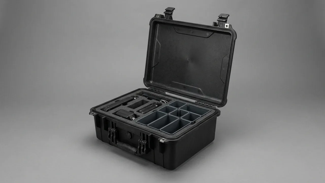
Seismic surveying is an industry built on laying thousands of sensors across open country and bringing every one of them back. A single 3D survey commonly deploys several thousand to more than ten thousand geophones, dozens to hundreds of acquisition units, and tens of kilometres of cable, all moved in by truck, pack animal and on foot. The conclusion up front: the measure of a seismic equipment case is not how much it holds, but whether four requirements hold at the same time, namely that geophone sensitivity and natural frequency do not shift, that acquisition unit memory and timing stay stable through vibration, that cable connectors take in neither water nor grit, and that a field crew can count and retrieve gear quickly while wearing gloves in poor light. In a geophysical crew's cost structure, repair and loss of equipment usually costs far more than the cases themselves. A geophone whose natural frequency drifts by ten percent can bias first-break picking across a whole spread, and one water-damaged acquisition unit can cost a full day of the acquisition window. This article works through each equipment family, giving protection parameters, the standards behind them and case architecture methods, for geophysical contractors, seismic instrument makers and exploration service companies.
Field rhythm rules out factory-style packaging. Desert crews work above 45 degrees C by day and near freezing at night, rainforest crews face 90 percent relative humidity year round, and cold-region crews work below minus 30 degrees C in winter, with condensation forming on case walls the moment a case is carried from the open into a tent. Shipping geophones and acquisition units in canvas bags and cardboard boxes produces five recurring problems on return to camp. Geophone tail spikes and shells take impact and natural frequency drifts, so every unit needs re-testing or scrapping. Memory card sockets and connectors in acquisition units loosen under resonance, producing missing channels or data gaps. Line cable connectors take in grit, contact resistance rises and the noise floor climbs. Decoders and source control units absorb moisture and fail field self-test. Cases break open during pack transport and geophones are scattered and lost along the route. These failure modes overlap with the sensor protection discussed for sonar transducer transit cases, but seismic work is distinctive in one respect: enormous quantities, moderate unit value and a very large aggregate loss.
Contents
- Seismic survey equipment families and their field transport damage map
- Geophones and digital sensors: one cavity per unit and vibration control
- Acquisition units and recorders: vibration control and data integrity
- Source control units and decoders: humidity control and connector protection
- Cables, line spreads and geophone strings: connector and grit protection
- What IP67 sealing means in field practice
- Humidity management: desiccant, indicators and vapour phase inhibitors
- Fast handling design: ergonomics for field crews
- Inserts and seals across the temperature range
- Static control and shielding: the hidden electrical risks
- Insert material selection: where EVA, PE, PU and XLPE each fit
- Transport and field drop validation: ISTA, ASTM D4169 and MIL-STD-810H
- Case formats for backpacking, pack animals and manual carries
- Frequently asked questions
- Conclusion and further reading
Seismic survey equipment families and their field transport damage map
A land seismic acquisition system normally splits into five equipment groups: geophones and geophone strings, acquisition units and seismic recorders, source control units including encoders and decoders, line and cross-line cable, and power, storage and tooling. Value density varies enormously. A moving-coil geophone is cheap per unit but deployed in huge numbers, so total value and total rework are considerable. An acquisition unit is expensive and far less numerous, and it contains analogue front ends, analogue to digital conversion, timing and storage, which makes it precision electronics. Decoders and source control units combine radio, satellite timing and self-test circuitry, and are the most humidity-sensitive items in the whole spread.
The table below gives the main weak point and the recommended zoning for each equipment family, and it can serve as the first check layer of a packing and counting list.
| Equipment | Main transport weak point | Recommended zoning |
|---|---|---|
| --- | --- | --- |
| Moving-coil geophone | Damaged tail spike, displaced spring leaf changing natural frequency, shocked magnetic circuit | One unit per compartment, tail spike cap fitted, never loose in bulk |
| Digital or MEMS sensor | Cracked accelerometer package, zero offset change, failed housing seal | Original blister tray plus secondary damping cavity, never stacked |
| Acquisition unit or recorder | Board resonance, loose memory socket, disturbed timing module | Antistatic bag, cavity gripped on four sides, removable damping cradle |
| Source control unit | Damp radio module, loaded antenna connector, bent pins | Separate soft-lined cavity, antenna and cables in their own bay, dust caps |
| Line and cross-line cable | Water and grit in connectors, over-tight bend radius, abraded jacket | Reel or large-diameter coil, dust and water caps on every connector |
| Geophone string and takeout | Stress concentration at the takeout root, tangling between strings | One hanger per string, takeouts secured and never left hanging |
| Lithium battery pack | Short circuit, crushing, heat, state of charge management | Packed separately to UN38.3 practice, insulated terminals, never with loose metal |
| Tooling and accessories | Loss, corrosion, mixed specifications | Compartmentalised and labelled, packed as complete functional sets |
Looking at damage mechanics, transport failure in seismic gear differs from ordinary industrial parts. The problem is not heavy items crushing light ones, but performance drift driven by continuous vibration combined with grit abrasion. A geophone's natural frequency comes from the mechanical balance between spring leaf and inertial mass, and the impact from a single one metre drop can leave a small plastic deformation in the spring leaf, moving frequency from 10 Hz to 10.8 Hz with no visible external trace. Acquisition unit failures more often start with board resonance and fretting wear in connectors, showing up as raised channel noise or occasional data gaps: the unit passes despatch inspection and only fails in the field.
One more link is routinely overlooked: the takeout and connector of a geophone string, which is the weak joint of the whole spread. If the takeout root is flexed repeatedly in transit, strands break inside. In the field this shows up as a handful of dead channels, and the crew walks the line joint by joint to find them, spending far more labour than the joint itself is worth.
Geophones and digital sensors: one cavity per unit and vibration control
Geophones are the most numerous item in seismic equipment, and the design objective is one unit per cavity, restricted movement, no hard contact. A moving-coil geophone consists of a housing, a magnetic circuit, a spring leaf and an inertial mass, with natural frequencies commonly at 4.5 Hz, 10 Hz and 28 Hz, and damping coefficient and sensitivity as factory calibrated parameters. Once those three parameters shift because of transport shock, the unit still produces a signal but it is no longer a conforming part.
The method has four steps.
First, one unit per compartment. Cut the insert to follow the geophone outline including tail spike and lead wire, with a single unit in each compartment and never loose in bulk. Print the compartment count on the case nameplate so quantities can be verified by counting, rather than assuming that a full-looking case is a complete one.
Second, treat tail spike and shell separately. The tail spike concentrates load and should carry a plastic or rubber cap. Leave 2 mm to 3 mm of clearance between shell and compartment wall rather than an interference fit. For metal-shell geophones use neutral PE or EVA for the compartment wall, because soft PVC with migrating plasticisers dulls and contaminates surfaces over long contact.
Third, restrict vertical movement. Add a hold-down pad above each compartment so the geophone is pressed without being crushed, with pad compression held between 15 and 25 percent. Supporting from below while doing nothing above is the most common defect in field cases: units jump compartments and strike each other on rough roads.
Fourth, route lead wires and string cable separately. Take the string lead out through a side channel with a rounded inner edge so no sharp lip cuts the jacket. Never lay the wire bundle across the geophones and never let it span between compartments.
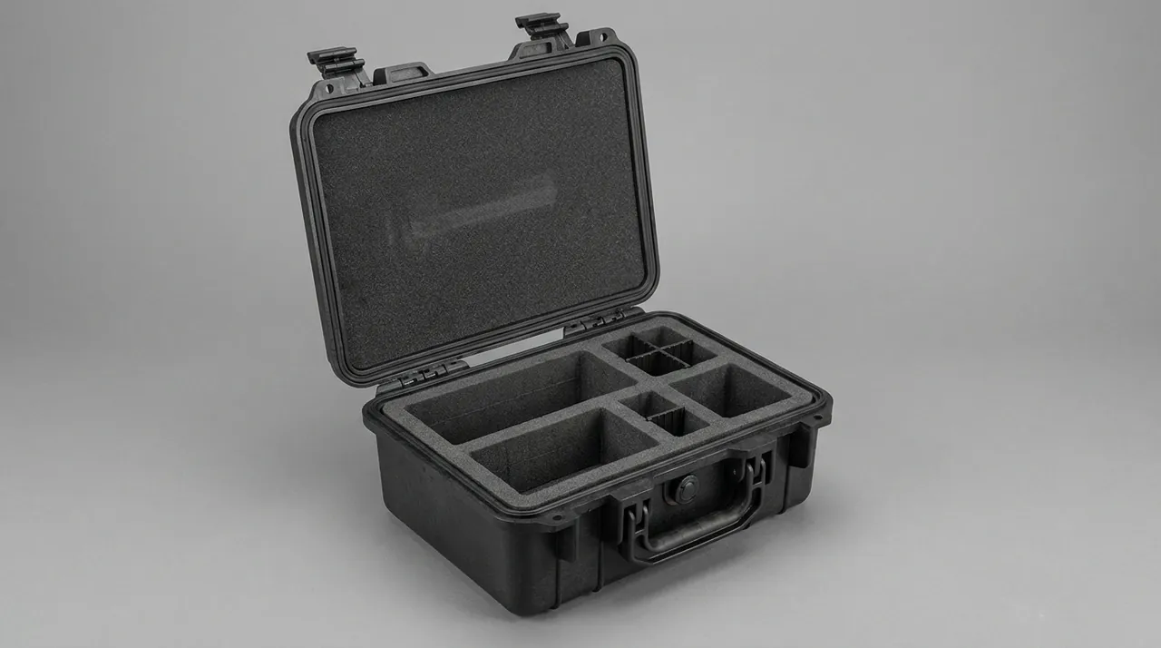
Digital sensors and MEMS accelerometers demand more. Their sensing elements are micro-machined structures, sensitive to both high-frequency shock and electrostatic discharge. Beyond the damping requirements above, keep the original blister tray and place the whole tray into a secondary damping cavity, and have operators discharge personal static before touching an electrical interface. Avoid open-cell foam that sheds inside the case, because debris can migrate into connectors.
Working figure: the inertial mass of a 10 Hz moving-coil geophone weighs only a few grams, and the stress margin of its suspension spring leaf under drop shock is limited. Practice in the industry is to keep a single unit's drop height below 0.5 m and to require that natural frequency and sensitivity remain inside calibration tolerance after a one metre case drop.
Site handover should follow a three-step sample check. Inspect appearance first, covering tail spike, shell and lead wire root. Then measure natural frequency and damping on a portable tester, sampling two to five percent per batch. Finally verify quantity against string numbers. If any step is out of tolerance, widen the sample rather than swapping a single unit.
Acquisition units and recorders: vibration control and data integrity
Acquisition units and seismic recorders carry the value of the whole system, since one unit often serves dozens of channels. Inside are the analogue front end, 24-bit conversion, timing and synchronisation, storage and battery. The keywords are vibration control, moisture control and static control, and data integrity is the combined result of all three.
The first damping principle is to avoid suspension. Boards and internal storage are sensitive to resonance in the 20 Hz to 200 Hz band, which is exactly where truck suspension and pack animal gait put their energy. The insert must grip on four sides rather than only cushioning underneath, with 3 mm to 5 mm of elastic compression so the unit sits in contact without pressure. Where a unit has its own isolation cradle, fit a shipping pin or rigid support block so the isolator cannot travel freely and hammer its end stops.
Moisture control needs two levels at once. At unit level, an acquisition unit is usually rated IP67 or better, provided that connector caps, battery compartment seals and card door are all properly closed. Confirm cap closure unit by unit before loading, and do not rely on case sealing to compensate for a unit that was left open. At cavity level, fit indicating desiccant and, for sea freight or long wet-season routes, add vapour phase corrosion inhibitor to protect connector pins.
Static control is directly tied to data integrity. Memory cards and solid state storage are static sensitive, so use antistatic gloves or a wrist strap when handling, and avoid non-conductive inserts that build up triboelectric charge. Where crews must swap media frequently in the field, provide a dedicated swap station inside the case with conductive foam holding media low in the cavity, rather than letting crews carry cards loose in a pocket where they bend and pick up static.
| Risk source | Typical symptom | Protection measure | Field verification |
|---|---|---|---|
| --- | --- | --- | --- |
| Board resonance | Raised channel noise, occasional data gaps | Four-side grip, 3 to 5 mm elastic compression | Check insert impressions for even marking on opening |
| Storage micro-movement | Read and write errors on disk or solid state media | Separate damping cradle, shipping pin | Power-up self-test and channel consistency test |
| Moisture ingress | Self-test failure, oxidised interfaces | Unit caps closed, desiccant, vapour phase inhibitor | Desiccant indicator colour, connector appearance |
| Static discharge | Permanently dead channel, corrupted storage | Antistatic insert, grounded handling | Insert surface resistance, work practice audit |
Battery packs need separate comment. Lithium batteries must meet UN38.3 testing, and packing should insulate terminals, keep each pack separate, avoid sharing a cavity with loose metal and display the lithium battery mark on the outer case. If the equipment must ship energised, state the state of charge limit and declare it to the carrier as required. For the air leg, the dangerous goods packaging requirements in hazardous goods transport cases are a useful reference.
Source control units and decoders: humidity control and connector protection
Vibroseis work depends on the radio link and satellite timing between encoder and decoder. This hardware is small, connector-rich and carries external antennas, so transport protection focuses on interfaces and antennas rather than on the enclosure.
Connector protection has three points. First, fit matching dust and water caps to every exposed connector in transit. Do not substitute tape, because adhesive residue contaminates the sealing faces and changes the feel of later mating. Second, store cables apart from units. A cable under vibration behaves like a whip, and if it shares a cavity with a unit the connector root takes repeated bending stress; provide a dedicated cable bay, or coil the cable into a large loop and tie it. Third, if antennas and antenna bases are removable, pack them separately in soft lining. If they are fixed, build a support guard around the antenna so that external impact does not reach the base.
Moisture treatment must cover both static storage before power-up and thermal cycling during work. The first depends on desiccant and case sealing, the second on the unit's own sealing design. When a unit is carried from a 5 degrees C night into a 40 degrees C tent, the air inside the case warms faster than the hardware, and condensation forms on cold surfaces. A case fitted with a pressure equalisation valve relieves that differential while keeping its sealing classification, cutting the inward rush of moist air at the moment of opening; the mechanism is described in protective case pressure equalisation valves.
One further requirement is easy to miss. Source control units often work alongside high-pressure hydraulic vibrator components, so equipment cases must not contact hydraulic oil or grease. Once oil soaks into an insert, the foam releases odour for a long time, holds dust and contaminates connector sealing faces. Provide a replaceable oil barrier layer inside the case, or set an explicit rule that oil products and electronics travel in separate vehicles.
For units with radio modules, switch off and disconnect the battery for transport so the unit cannot wake up, drain the pack or emit radio frequency interference. Fit a guard over the power button. These details look minor, but the most common field complaint about a unit that will not start traces back to a battery drained by accidental power-up.
Cables, line spreads and geophone strings: connector and grit protection
Cable is the bulkiest and most easily damaged family in seismic work. Functionally it divides into line cable, cross-line cable, geophone strings and takeout leads; structurally it is mostly multi-core screened cable with circular sealed connectors. Failures concentrate in exactly two places: the connector and the cable root.
Connector protection is about keeping water and grit out. In transit, cap every male and female connector with its matching dust cap, and place a little desiccant inside the cap. Connectors must not rest directly on the case floor; put them in lined channels or on hangers. Connectors recovered from the field usually carry mud and fine sand, so clean before packing rather than packing dirty. Once grit enters the pin chamber, the next mating abrades the plating and contact resistance rises.
Bend radius is the key point for the cable body. Line cable is multi-core, and repeated tight bending fatigue-fractures the copper conductors. For transport, a coil radius of at least ten to fifteen times the cable outside diameter is advisable; for 10 mm line cable, keep the coil diameter above 200 mm. Where a reel is used, fit side plates so the coil is not crushed in transit. Where cable is coiled without a reel, cross-tie it at four points to prevent it twisting into itself.
| Cable item | Main damage mode | Transport attitude | Connector treatment |
|---|---|---|---|
| --- | --- | --- | --- |
| Line cable | Abraded jacket, fatigue-broken conductors | Reel or large-diameter coil with side plates | Dust and water caps both ends |
| Cross-line cable | Loaded connector, tangled coil | Separate hanger or compartment, never with heavy items | Connectors secured, not hanging |
| Geophone string | Broken strands at takeout root, tangling | One hanger per string, takeouts facing the same way | Strain relief sleeve at takeout root |
| Jumper lead | Loss, mixed specifications | Compartmentalised and labelled, kept as sets by length | Bundled as a set and labelled |
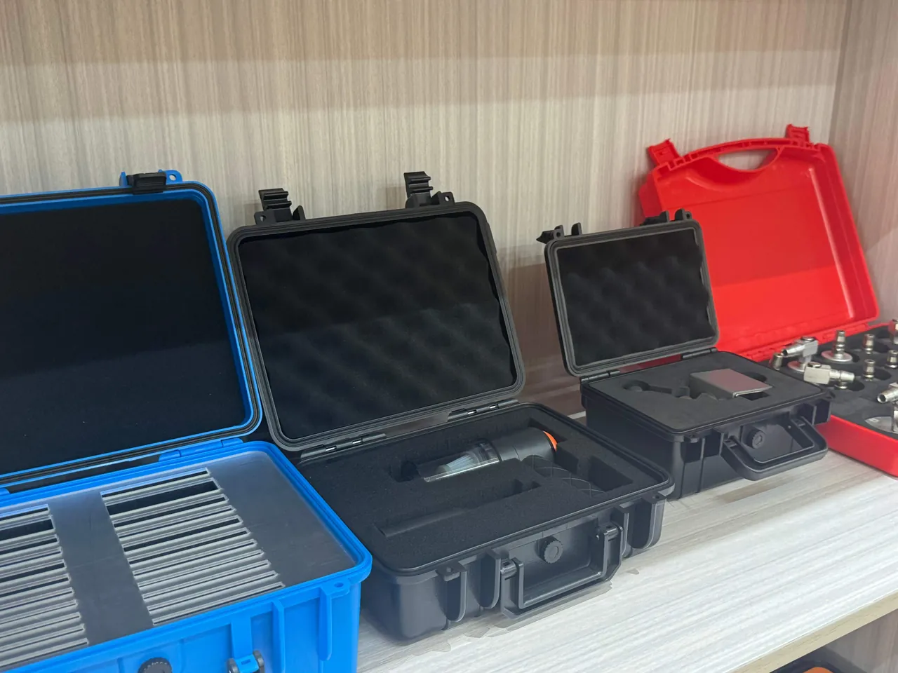
The geophone string takeout is the part that most needs detailed design. The takeout root is a classic stress concentration, and any hanging load in transit converts into broken strands inside. Fit a strain relief sleeve, using heat shrink or a rubber boot, and secure the takeouts along one direction on the hanger so the hanger carries the load rather than the conductor. As with the watertight connectors discussed for transducer cable and sealing, takeout reliability is set jointly by assembly process and transport protection.
Counting matters especially for cable. Print specification and quantity plates inside the case and follow a one-bay-one-specification rule so crews do not estimate specification by eye. Where many cable types are similar in length, a removable divider system lets the layout follow the work batch, cutting wrong picks and losses.
What IP67 sealing means in field practice
Field requirements for case protection can be stated in one line: keep rain out, keep grit out, survive short immersion. The classification basis is IEC 60529, with its Chinese equivalent GB/T 4208, where the first digit covers dust and the second covers water. IP67 denotes dust tight plus no harmful effect after defined short immersion, typically one metre for thirty minutes.
| Field condition | Main threat | Suggested rating | Note |
|---|---|---|---|
| --- | --- | --- | --- |
| Camp cabins and vehicle transfer | Airborne dust, occasional rain | IP55 | Entry configuration for short covered routes |
| Desert and gobi | Continuous fine sand ingress | IP65 | Dust is the priority, rubber parts must resist dry heat ageing |
| Hills and plains in the rainy season | Sustained rain, mud spray | IP66 | Strong water jets, hinges and latches need mud protection |
| Rainforest and swamp | High humidity, standing water, wading carries | IP67 | Covers short immersion, seals must resist hydrolysis |
| Cold regions with freeze-thaw | Ice water immersion, hardened seals | IP67 | Verify seal elasticity at minus 30 degrees C |
An IP rating describes how hard it is for external media to enter the enclosure, and does not mean internal humidity stays controlled. Geophone and acquisition unit sensitivity to moisture comes from two directions: electrochemical corrosion of metal parts, and falling insulation resistance in connectors. The correct approach therefore combines a sealed shell with internal humidity management. The shell stops liquid water and grit, while desiccant and humidity indicators control vapour phase humidity inside, and vapour phase inhibitor protects bare metal surfaces. With sealing alone and no internal management, condensation can still appear inside a case after sea freight through the tropics. The correspondence between rating and construction is set out in waterproof case IP ratings and IP67 protective cases.
One further field consideration is repeated opening. A survey crew opens its cases once or several times a day, so gasket and latch wear runs far ahead of a warehouse scenario. Choose a case with a replaceable gasket and individually replaceable latches, and state the replacement interval at handover. Hinge, latch and gasket fit determines whether a dust path remains once the lid is closed, which aligns with the structural points in case hinge, latch and seal construction, with one extra field requirement: the case must lock one-handed through a heavy glove.
Humidity management: desiccant, indicators and vapour phase inhibitors
For a geophysical crew, moisture control is not a one-off packing action but a continuous process spanning factory, sea freight, warehouse, field and return to camp. The case is only the carrier for that process.
Desiccant selection and quantity should be argued with numbers. Silica gel at 25 degrees C and 60 percent relative humidity absorbs roughly 20 to 30 percent of its own weight; molecular sieve performs better in the low humidity range but needs a higher regeneration temperature. A practical sizing rule is 20 g to 30 g of silica gel per 10 litres of free air volume inside the case, taking the upper figure for sea freight or humid regions, and keeping at least 30 percent margin because every opening and every older gasket raises the moisture ingress rate.
Humidity indication works best with two elements. A colour indicator card allows immediate visual judgement against a threshold. An irreversible maximum humidity card records the peak across the whole journey, which is particularly useful when responsibility has to be established: if the card shows a peak far above threshold, a seal failure occurred somewhere in transport or storage.
Vapour phase corrosion inhibitor suits connector pins, screws and metal housings. Three usage points apply. First, the inhibitor carrier should not sit in direct contact with optical parts or rubber seals, because volatiles can affect material performance. Second, the inhibitor needs a reasonably enclosed space to build a protective atmosphere, so case sealing is a precondition. Third, the inhibitor has a shelf life, and past that date it must be replaced rather than stretched.
| Control measure | Target | Usage point | Replace or check interval |
|---|---|---|---|
| --- | --- | --- | --- |
| Silica gel desiccant | Vapour phase humidity inside the case | 20 to 30 g per 10 litres free volume | Indicator colour change, or end of each season |
| Molecular sieve desiccant | Continued adsorption at low humidity | Higher regeneration temperature, better replaced whole | Judged by moisture indicator |
| Colour indicator card | Fast visual judgement | Fixed where it is visible on opening | Every opening |
| Maximum humidity card | Peak record across the journey | Filed as a responsibility record | After each transport batch |
| Vapour phase inhibitor | Connector pins and fasteners | Kept clear of rubber and optical parts | Per manufacturer shelf life |
Note that desiccant cannot substitute for cleaning. Mud carried back inside a case keeps releasing moisture into the vapour space and saturates the desiccant quickly, so clean before packing should be written into crew rules as a hard requirement.
Fast handling design: ergonomics for field crews
A field case differs fundamentally from a factory tote because the user wears thick gloves, works in poor light, is short of time and often has no level surface to work on. Those constraints should translate into specific structural requirements rather than a vague wish for easy access.
The first is the opening action. Single-action opening, one latch released and one push to close, suits field tempo better than multiple catches. Where the lid is a hinged type, fit gas struts or a stay so it holds position and is not blown over; in windy areas this matters greatly, because a falling lid both traps fingers and spoils the gasket impression.
The second is layered visibility. Where a case has two or more layers, the upper layer should be a removable tray or basket so that lifting it out exposes the whole lower layer, rather than leaving a deep cavity to grope in. For high-count items such as geophones, a shallow many-column layout lets every unit be seen and reached directly.
The third is counting efficiency. Label each compartment with a number and the quantity it should hold, and fix a counting sheet inside the lid. For items that belong to a set, such as a string of six, count by string rather than by unit, which sharply reduces miscounts. Crews using barcode or tag management can provide a tag station inside the lid, so labels are not covered by mud on the outside.
The fourth is the carry format. Manual carries are often long, so the case should offer a stowable shoulder strap or harness with padding on the back face. When carried on the back the centre of gravity should sit close to the spine, which means limiting case thickness. For pack animal transport, the case needs corner protectors and top strap loops for lashing, and its drop and crush requirements should be raised one level above the vehicle scenario.
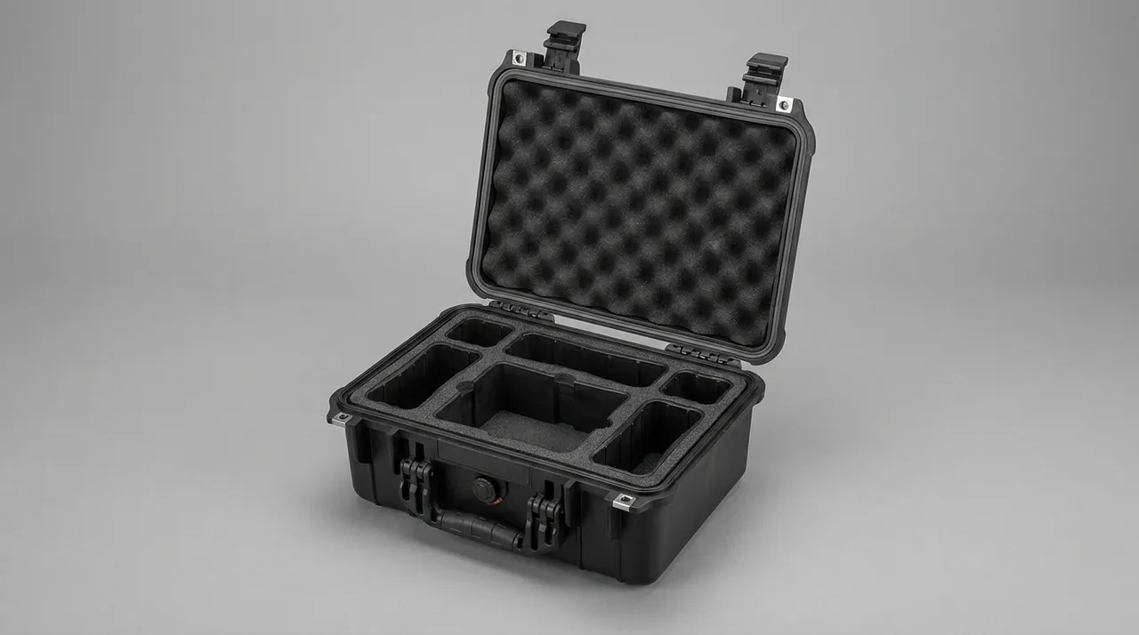
Fast retrieval must be matched by fast repacking. Crews finish at dusk, when gear is most likely to be thrown back into the case. Use physical means to guide correct repacking: make compartment shapes match item shapes so a wrong placement stops the lid closing, and use hooks rather than pockets in the cable bay so a missing item leaves an empty hook. This follows the same principle of structure guiding correct behaviour described for removable divider systems.
Inserts and seals across the temperature range
Seismic work spans desert to high cold, and case materials must function across that range. Temperature affects a case through three paths: inserts hardening or softening, seals losing elasticity, and breathing driven by thermal cycling.
On inserts, EVA hardens progressively at low temperature and loses resilience. Ordinary PU foam becomes noticeably brittle below minus 20 degrees C and hydrolyses in sustained high humidity. PE foam performs comparatively well in cold but has moderate resilience. XLPE keeps useful flexibility at low temperature and suits the cushioning layer in cold-region work. Ask suppliers for low temperature data rather than judging by feel at room temperature.
On seals, nitrile rubber has good oil resistance but moderate low temperature behaviour. Silicone rubber holds stable elasticity from about minus 50 to plus 200 degrees C and is a common choice for wide-range field cases. EPDM offers excellent weathering and hydrolysis resistance and suits rainforest and high humidity work. Note that silicone is sensitive to certain oils and solvents, so compatibility must be assessed where oil products are present nearby.
| Temperature regime | Insert suggestion | Seal suggestion | Particular caution |
|---|---|---|---|
| --- | --- | --- | --- |
| Ambient minus 10 to plus 40 degrees C | EVA 40 to 60 kg/m3 | Nitrile or EPDM | General configuration |
| Hot desert above plus 50 degrees C | PE or high density EVA | EPDM for heat ageing | Prevent softened material sticking to hardware |
| Cold below minus 30 degrees C | XLPE cushion layer with low temperature EVA | Silicone rubber | Opening torque rises, latches should be adjustable |
| Humid rainforest | Closed cell PE or EPP | EPDM for hydrolysis | Prevent water uptake and mould in inserts |
| Freeze-thaw cycling | Closed cell material, no open cell water uptake | Silicone or EPDM | Check sealing after ice water immersion |
Breathing driven by thermal cycling is pronounced in the field. The case warms by day, internal pressure rises and air bleeds slowly out through the seal; it cools at night, pressure falls and moist air is drawn back in. Repeated cycling drives internal humidity toward ambient. Mitigation includes a pressure equalisation valve with a waterproof breathable membrane, and control of opening time, for example opening early in the morning and avoiding long open periods at midday. Broader material and architecture guidance for wide temperature duty is given in wide temperature protective cases.
Static control and shielding: the hidden electrical risks
Seismic acquisition front ends work at microvolt signal levels, and both electrostatic discharge and external electromagnetic interference show up directly in data quality. Transport looks like an electrical non-issue, but at least three pathways connect the two.
The first is static accumulation. Carrying a case in a dry environment, common in deserts where daytime relative humidity falls below 20 percent, generates triboelectric charge. If the insert is insulating and the equipment has no discharge path, a discharge can pass through a connector at the moment of handling. Use dissipative inserts with surface resistance in the 10^6 to 10^9 ohm range, or cover an insulating insert with a conductive textile layer, and provide a grounded station for media handling. Insert construction and verification for dissipative materials is described in ESD shielding cases.
The second is shielding integrity. Where an acquisition unit has a metal housing, its shielding and grounding behaviour depends on whether the case creates an unintended ground path. In transit, avoid sustained contact between the housing and a metal case frame, which would wear the plating under vibration, and avoid hard inserts that scratch the shielding layer.
The third is magnetic interference. Magnetic fixtures on vehicles or pack harnesses, such as magnetic bases and magnetic tools, should never travel in or immediately beside a case holding geophones or acquisition units. The magnetic circuit of a moving-coil geophone is sensitive to strong external fields, and long exposure close to a strong magnet can show up as a sensitivity deviation during calibration.
For cases carrying spare media, batteries and tooling, apply electrical zoning: main unit zone, media zone, battery zone and tool zone kept separate, so that metal tools cannot roll against a connector under vibration. This zoning principle parallels the metrological-risk zoning used for gauge block cases, with the risk type changed from dimensional accuracy to electrical performance.
Insert material selection: where EVA, PE, PU and XLPE each fit
The insert is the mechanical interface between case and hardware, and its selection decides whether damping, moisture control, static control and counting efficiency all hold at once. The field difference from a factory setting is that the case must survive a wide temperature range, repeated opening and manual carries, so selection depends on low temperature behaviour, water uptake and abrasion resistance as much as on softness.
| Material | Density range | Where it fits | Main shortfall | Typical items |
|---|---|---|---|---|
| --- | --- | --- | --- | --- |
| EVA | 40 to 70 kg/m3 | General compartment inserts from ambient down to minus 10 degrees C | Hardens at low temperature, resilience falls | Geophones, decoders |
| PE | 25 to 50 kg/m3 | Cushion layers and dividers for humid and rainforest duty | Moderate resilience, collapses after compression | Cable bay dividers, tray cushions |
| PU | 35 to 70 kg/m3 | Load-bearing saddles and compression blocks | Hydrolyses in high humidity, brittle when cold | Acquisition unit cradles, battery blocks |
| XLPE | 30 to 60 kg/m3 | Cushion layers for cold region work | Higher unit price, demanding forming process | Cold region equipment cases |
| Dissipative foam | 30 to 60 kg/m3 | Handling zones requiring static control | Surface resistance drifts with humidity | Media stations, controller area |
Beyond the material itself, three process points deserve emphasis. The first is compartment tolerance: a contoured compartment should be roughly 2 mm to 3 mm larger than the item on each side, working with a hold-down pad above to create full restraint from both directions. An interference fit loads hardware continuously and actually accelerates deformation of seals and housings. The second is channel design: channel width should exceed cable bundle diameter by a factor of 1.2, inner edges should be radiused, and a transition slope should link channel and compartment so wire is not flexed repeatedly over a sharp lip. The third is serviceability: attach inserts with nylon rivets or hook and loop so that field damage can be repaired locally by the crew instead of returning the whole case. Foam forming and tolerance control are covered in custom EVA foam insert processes.
For high-count geophone cases there is a more economical approach: a common base tray with plug-in divider blades. One case then adapts to different geophone outlines such as 10 Hz and 4.5 Hz by changing blades, and a single damaged compartment can be replaced in the field.
Transport and field drop validation: ISTA, ASTM D4169 and MIL-STD-810H
Validation of a field equipment case cannot simply copy an industrial packaging sequence, because the logistics chain includes stages that ordinary packaging never meets: un-surfaced road travel, pack animal vibration, hand tossing at unloading and open air storage in the field.
| Standard | Nature | Correspondence to field duty | Suggested use |
|---|---|---|---|
| --- | --- | --- | --- |
| ISTA series | Transport packaging test procedures | Vehicle transport, stacking, drop | Select the sequence to the real chain, focus on insert compression after vibration |
| GB/T 4857 series | Basic tests for transport packages | General domestic acceptance | Use as the baseline and add field specific items |
| ASTM D4169 | Distribution cycle performance testing | Multi-leg movement by road, sea and inland | Assemble the test sequence from the distribution cycle |
| MIL-STD-810H | Environmental test methods, method reference only, not a military certification | High and low temperature, damp heat, vibration, shock methods | Borrow method and severity, make no certification claim |
This must be stated plainly. MIL-STD-810H is an environmental test method standard, and using its methods is not the same thing as holding a military certification. Outward documents should not claim certification.
Four practical points guide test design. First, the test article must be the production configuration, with the same insert material, gasket section and latch design as delivered. Second, vibration testing should cover the pack animal band, since the low frequency generated by a walking animal differs markedly from a vehicle spectrum, and validating only against a vehicle spectrum may underestimate fatigue at takeouts and connector roots. Third, drop testing should include corner and edge drops, because field tossing rarely lands flat, and after the test both case sealing and equipment electrical performance should be checked. Fourth, internal humidity should be a measured before-and-after parameter, using a maximum humidity card inside the case to judge whether sealing and desiccant configuration worked. A fuller breakdown of the procedures is given in ISTA transport testing procedures, and the graphical symbols of GB/T 191 and the general packaging conditions of GB/T 13384 should also be treated as acceptance criteria for marking and construction.
The way results are reported should also be standardised. Supply a validation summary with each case, listing test items, test article configuration, verdict and corrective action for any failure, with the testing body named. For a buyer, data that reveals the failure boundary is more valuable than a bare pass.
Case formats for backpacking, pack animals and manual carries
The last mile of a seismic survey often has no road. Gear comes off the vehicle and may then be carried two to five kilometres on foot, or moved by horse or yak to the line. Case format matters here as much as insert design.
The vehicle scenario turns on stacking and restraint. A case should have flat top and bottom faces for stable stacking, anti-slip pads at the base corners and lashing pockets or rings on the sides so it can be tied to the vehicle side rails. A near-cubic format makes best use of volume.
The backpack scenario turns on weight distribution and body fit. Provide stowable shoulder and waist straps, a padded back face and a contour that follows the spine, and keep the load centre near the geometric centre so the shoulders are not unevenly loaded. Keep single case weight below about 25 kg, and switch to a two person carry or add a wheel set above that.
The pack animal scenario turns on impact and crush resistance. A case on a pack saddle takes continuous lateral compression and irregular shock, so choose a format with reinforced corners and ribbed side walls, corner protectors and top strap loops, and avoid very flat or very slender shapes that cannot be lashed stably on a pack saddle.
| Carry method | Main load character | Suggested case format | Accessory requirements |
|---|---|---|---|
| --- | --- | --- | --- |
| Vehicle | Stacking static load, low frequency vibration | Near cubic, flat base | Anti-slip base pads, lashing rings |
| Backpack carry | Local pressure, swinging | Spine contour, moderate thickness | Stowable shoulder and waist straps, back pad |
| Two person carry | Concentrated load at handles | Symmetric side handles, reinforced beams | Handle rating at least 1.5 times total weight |
| Pack animal | Lateral crush, random shock | Reinforced corners, ribbed walls | Corner protectors, top strap loops, rain cover |
Whatever the format, the case must be identifiable: carry a clear crew marking and equipment class marking, and state single case weight and centre of gravity. Where one crew uses several case sizes, standardise colour coding and numbering so loading and sorting stay orderly. Packing and transport symbols follow GB/T 191 and can be printed directly on the case, which reduces the problem of text that cannot be read in poor field light.
Frequently asked questions
Q: Can geophones be shipped loose in one case if soft foam separates them? A: It is not advisable. The core problem with bulk loading is insufficient restraint rather than insufficient cushioning. A geophone's natural frequency depends on the mechanical balance between spring leaf and inertial mass, and in a loose load the load state of every unit is undefined: the bottom layer carries the static weight above it, the middle layer can strike its neighbours under vibration, and the top layer can jump compartments. Soft foam lowers the peak impact but cannot restrict movement, so over a long journey the spring leaves take repeated micro-deformation and their stiffness changes, which shows up as natural frequency drift and sensitivity change. The correct approach is one unit per compartment with a contoured seat, support from below and a hold-down pad above to restrict vertical movement, with pad compression between 15 and 25 percent. If shipping capacity forces mixed loading, at least use rigid dividers between layers, independent compartments within each layer and cushioning between layers, and make sure no unit can cross between compartments. Bulk loading also makes counting difficult, and losses are often discovered only at the next opening, when the trail is already cold.
Q: Does the battery have to be removed from an acquisition unit for transport? A: It depends on the carrier and the equipment design, but either way the basic lithium battery transport requirements apply. For air freight, cells are normally required to be switched off, terminals insulated and either packed separately or declared under the applicable provisions for equipment containing batteries, and a state of charge of no more than 30 percent of rated capacity may be required, all according to the carrier and the applicable dangerous goods rules. Sea and road transport are less restrictive but still require insulated terminals and protection against crushing and short circuits. From a protection standpoint, removing the battery for separate shipment has two benefits: it lowers overall unit weight and centre of gravity, reducing inertial load on the insert, and it avoids keeping the battery at high temperature inside the case for long periods. The risk is that repeated connection and disconnection wears the terminals and the pack may be left out in the field. A middle path is to leave the battery installed but isolate the main circuit with a shipping insulator, and to include a pre-loading and pre-power-up checklist card in the case, listing terminal insulation and switch state as handover confirmation items.
Q: Once grit gets into line cable connectors, can they be cleaned and reused, and how is that judged? A: In most cases they can be cleaned, but the damage level must be assessed. Light contamination shows as a rough mating feel and fine sand on surfaces; treat it with dry compressed air, wipe pins and sockets with anhydrous alcohol, inspect the seal for deformation or cuts, and after replacing the seal apply the specified silicone grease. Moderate contamination shows visible wear marks on pins with the plating not yet penetrated; measure contact resistance first, and if the deviation from the factory value is within the permitted range the connector can continue in service but should be tagged as a watch item with a shortened recheck interval. Severe contamination means plating worn through to base metal, bent or broken pins, or clearly raised contact resistance; these connectors should be scrapped and replaced, not sanded back into service, because abrasion removes more plating and changes pin diameter, producing a loose fit and repeated failures. The key instrument is a micro-ohmmeter able to read milliohm values, plus a set of reference values from a new connector. For prevention, caps on every connector in transit and a clean-before-packing rule are essential.
Q: How long does an IP67 field case actually stay watertight in service? A: IP67 describes the outcome of a type test on a new case, and real service life depends on how fast the seals wear and how intensively the case is used. A survey crew opens its case once or more per day, so the gasket takes repeated compression and develops permanent set, and latch clamping force falls as the mechanism wears; at the same time grit entering the sealing face cuts microscopic channels. Experience suggests that under heavy use a gasket typically needs inspection and replacement within one to two working seasons, and that interval should be shortened further where sand is abundant or the case is regularly carried through mud. Measures that extend service life include choosing a case with a replaceable gasket and individually replaceable latches, checking the sealing face for sand before every closing, rinsing the case exterior with clean water before opening, and running a simple spray self-check at intervals. Remember that IP67 does not guarantee controlled internal humidity, so desiccant and humidity indicators still need scheduled replacement and review.
Q: Between geophones and acquisition units, which has the higher protection priority? A: Acquisition units carry the higher financial risk and geophones carry comparable mission risk, so it is better not to rank them but to design separately by loss pathway. A single acquisition unit is worth far more than a single geophone, and its failure can stop a whole spread, so its protection target is zero failure: four-side grip, a separate damping cradle, an antistatic insert and strict humidity management all have to be in place. A geophone is inexpensive but deployed in enormous numbers, and its risk profile is large-scale performance drift plus loss. If three percent of ten thousand geophones fall outside natural frequency tolerance, data quality in the problem area is affected, and geophones are the item most easily left behind in the field, where the combined cost of loss and recount labour far exceeds the unit price. A sound approach is to set different acceptance metrics for the two families: for acquisition units, power-up self-test pass rate and channel consistency; for geophones, sampled natural frequency pass rate and quantity reconciliation rate, each with its own case configuration.
Q: Why should a field case format be designed around the carrying method? A: Because each carrying method imposes a different load character on the case, and one format covering all of them sacrifices both performance and cost. Vehicle transport applies stacking static load and vehicle vibration, so the case needs flat top and bottom faces and stable stacking, where a near-cubic shape improves volume utilisation and the priority is compression and stacking resistance. Backpack carry applies local pressure and swinging, so the case needs a spine contour, stowable straps and a back pad, with single case weight held within a range that can be carried for hours, and the priority is ergonomics. Pack animal transport applies lateral crush and irregular shock, so the case needs reinforced corners, ribbed walls and reliable lashing points, and the priority is impact and deformation resistance. The three scenarios pull wall thickness, ribbing and accessories in different directions, so on projects with complex terrain and multiple transfer stages a combination of a vehicle main case and backpack sub-cases is usually more economical than a single format, and it protects the equipment better.
Q: If the humidity indicator card shows an over-limit reading, does the equipment have to be sent for repair? A: Not immediately, but a graded handling flow is required. Step one is isolation: set the affected case aside so its contents are not mixed with conforming equipment. Step two is appearance and function checking: look for rust points on metal parts, oxidation on connectors and deformed seals; sample geophones for natural frequency and sensitivity and run power-up self-test plus channel consistency on acquisition units. Step three is graded disposition. If appearance and function are both normal, dry the contents by opening the case in a low humidity space or using a dry cabinet, then repack with fresh desiccant. If there are light rust points but function is normal, clean and treat the surface, apply corrosion protection, and downgrade the items to non-critical lines. If function tests are out of tolerance, send the items for repair. Step four is root cause: read the peak value and timing from the humidity record card, decide whether a seal failed, desiccant expired or the case was not resealed in time, and write the conclusion back into the crew procedure. Where only the indicator card is over limit and no functional abnormality appears, scrapping the equipment is not warranted.
Q: Is a custom moulded insert really necessary for a seismic case, or is generic foam with dividers enough? A: Generic foam with dividers can work temporarily where quantities are small and equipment specifications are uniform, but for a standing crew with large volumes and consistent models a custom insert pays back better. Three benefits stand out. First, restraint consistency: moulded compartments hold tolerance, so full restraint from below and above can be guaranteed, whereas hand-cut foam cannot hold the same tolerance everywhere and protection varies across the case. Second, counting efficiency: moulded compartment positions are fixed, so a lid counting sheet enables fast reconciliation, while divider layouts drift with user habit. Third, service life: moulded inserts use validated density, so compression set is predictable, and a modular design lets one damaged compartment be replaced rather than the whole insert. Where models change often, a common base tray with plug-in divider blades is a middle path. Tooling cost should be assessed against crew size, as set out in the custom foam insert guide.
Conclusion and further reading
A seismic equipment case shows up in two measures: data quality and crew productivity. Essentials: one compartment per geophone with two-sided restraint, four-side grip plus static and humidity control for acquisition units, strain relief at takeouts and connectors, materials rated for IP67 and the full temperature range, and a format matched to carrying method. JUNZHIJIA builds these cases to order.
Further reading