

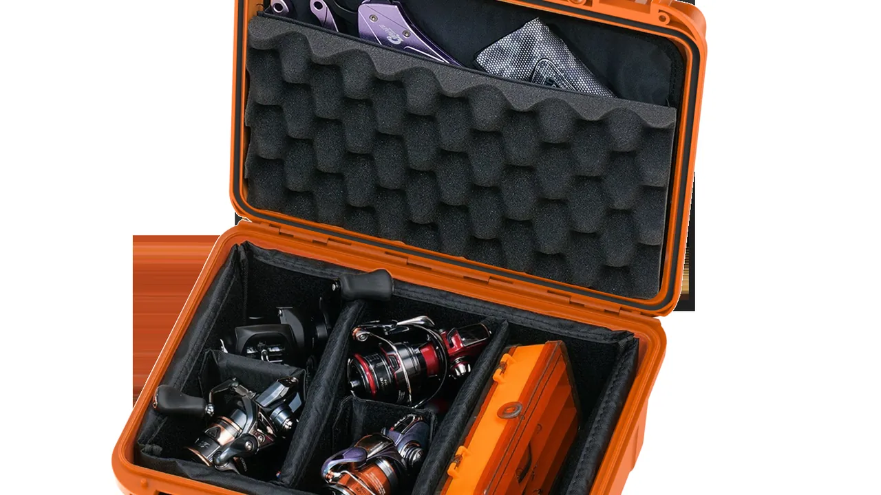
Sonar transducers travel from the manufacturing plant to shipyard outfitting, from the quay aboard a vessel, back to the factory for repair, or as spares carried with a fleet. They are the classic high-value, low-quantity, irreplaceable item. The conclusion is unambiguous: hydroacoustic transducer arrays, sonar electronics cabinet units and towed cable connectors must be packed by component class rather than as generic cargo. The acoustic face must never be compressed and never scratched, and may only ever touch soft materials. Array elements must hold their relative positions inside locating cavities so they cannot drift. Electronics cabinets must be rack-mounted on vibration isolators that limit the relative movement of boards and the backplane. Towed cables and their connectors must be coiled at a bend radius no smaller than the maker's limit with proper stress relief at the termination. The case itself must be sealed to IP67 (IEC 60529 / GB/T 4208), upgraded to IP68 immersion duty where the route demands it, and layered with marine salt fog corrosion protection and vibration damping, so the parts can go straight onto the acoustic re-test bench after long sea voyages and repeated handling. Leaving a transducer bare in a wooden crate, using cardboard to pad the corners, or coiling cable by hand is the most common field error.
The transport risk profile of sonar equipment differs from that of ordinary oceanographic instruments because it involves three things that cannot be repaired after the fact: acoustic performance, watertight integrity and corrosion resistance. Once the acoustic face takes a permanent dimple or a scratch, the acoustic impedance characteristics of the transparent layer and the matching layer change with it, and sensitivity and directivity drift in ways that are difficult to correct. Once the watertight structure takes an impact in transit and the sealing face deforms microscopically, leakage only appears after the unit is submerged in service, at which point recovery and repair are extremely expensive. Salt fog corrosion advances slowly over months, starting at fastener threads and eventually reaching galvanic contact surfaces. Add to this the small batch quantities, high unit value and long repair turnaround of sonar equipment, and the return on transport protection investment is genuinely favourable. This article sets out protection structures, sealing grades, cushioning parameters and acceptance clauses by component category, for the technical and procurement staff of sonar OEMs, marine electronics suppliers, ocean survey organisations and fleet support departments.
Table of Contents
- Typical Failure Modes in Sonar Transducer Parts Transport
- No-Compression, No-Scratch Protection of the Transducer Acoustic Face
- Array Compartmentalization and Element Position Retention
- Watertightness and Moisture Control: IP67 Sealing and Immersion Boundaries
- Marine Salt Fog Corrosion and Galvanic Isolation of Metal Parts
- Rack and Board Retention in Sonar Electronics Cabinet Units
- Bend Radius and Stress Relief for Towed Cables and Connectors
- Low Outgassing and Cleanliness Control for Acoustic Materials and Acoustic Windows
- Shock and Vibration Damping: Vibration Sensitivity of Transducers and Hydrophones
- Case Body Material, Seals and Pressure Equalization Valve Selection
- Temperature, Humidity, Condensation and Desiccant Configuration
- Transport Compliance Testing and Acoustic Re-Test on Arrival
- Sea Freight, Lifting and Stacking Markings
- Case Rotation, Cleaning and Spares Management for Marine Projects
- FAQ
- Conclusion and Further Reading
Typical Failure Modes in Sonar Transducer Parts Transport
Field feedback from recent years clusters sonar equipment transport damage into four classes. The first is acoustic face damage: dimples pressed into the acoustically transparent rubber layer, grooves cut by sharp objects, contamination by adhesive residue. The root cause is direct contact between the acoustic face and a hard support, or mutual compression between adjacent items. The second is structural damage: cracks in the piezoelectric ceramic stack under drop shock, debonding between the matching layer and the acoustic backing, leakage at the joint between the transducer housing and the mounting flange. Damage of this class frequently leaves no external trace yet puts measured performance out of specification. The third is electrical and watertight damage: bent pins in a watertight connector, chipped sealing faces, cable jackets crushed flat around an internally broken conductor. The fourth is corrosion and fouling: galvanic corrosion forming between fasteners and aluminium parts, blistering and flaking of plated layers, residual biological fouling that turns foul in humid conditions and corrodes the surfaces it sits on.
What all four classes share is delayed exposure. An acoustic face dimple can only be confirmed by acoustic re-test or underwater listening. A watertight defect only leaks after the first dive. Galvanic corrosion only becomes visible after months. A protection scheme must therefore deliver four properties at once: zero contact with the acoustic face, positive structural support, electrical protection, and corrosion isolation, together with the ability to re-test on arrival.
A further complication is that the failure modes interact. Impact energy absorbed by a soft liner that has already taken a compression set is redirected into the next most compliant path, which is usually a connector or a cable termination. A case that has been opened and resealed at sea with a salt-contaminated seal groove will pass a visual check and fail an immersion check. For that reason, protective packaging for sonar parts should be treated as a system whose elements are specified together, not as a box plus a bag of foam. The table below sets the failure focus of six core component categories alongside the corresponding protective action.
| Component category | Primary failure mode | Per-item protective action | Retention and support method | Process indicator (typical value) |
|---|---|---|---|---|
| --- | --- | --- | --- | --- |
| Hydroacoustic transducer (single unit) | Acoustic face dimples, ceramic stack cracking | Soft protective sleeve plus anti-scratch liner bag | Flange seated in a soft-lined cavity, radiating face suspended | No hard contact and no adhesive residue on the acoustic face |
| Transducer array | Element position drift, mating face misalignment | Individual sleeve for every element | Compartmentalized location blocks, element pitch locating blocks | Relative element displacement of 0.5 mm or less |
| Sonar electronics cabinet unit | Board loosening, backplane slot damage | Board retaining bars plus ESD bags | Rack rails locked, isolators at all four corners | Zero board displacement, no plastic deformation of isolators |
| Towed cable | Small-radius kinking, internal conductor breakage | Winding onto a large-diameter drum | Cable body carries no load, ends restrained | Bend radius not below the maker's limit |
| Watertight connectors and terminations | Bent pins, chipped sealing faces | Dedicated caps plus individual sleeves | Individually keyed positions, pins facing up | Sealing faces free of visible scratches |
| Acoustic window / fairing | Scratches, compression deformation | Curved soft cradles | Arc-shaped cradles matching the shell curvature | Uniform contact pressure with no point loading |
No-Compression, No-Scratch Protection of the Transducer Acoustic Face
The radiating face of a transducer is the only path by which sound enters and leaves the device. It is normally covered by a polyurethane or vulcanised rubber acoustic window, beneath which sit the matching layer and the piezoelectric ceramic stack. That face cannot be compressed, cannot be scratched and cannot even be taped casually, because adhesive residue creates a local acoustic impedance discontinuity that shows up as anomalous sensitivity during acoustic re-test.
The first principle of protection is that the acoustic face touches soft material only, and the contact pressure approaches zero. Fit a powder-free soft sleeve over the acoustic face first, then place the unit into its cavity. Chloroprene rubber and expanded PE both work, provided neither sheds particles. The cavity is relieved on the acoustic face side so that face is fully suspended, and all support is taken by the mounting flange or by the side wall of the housing.
Cavity material must be free of sharp corners. Every corner that can touch the part should be radiused at R5 or larger, and the liner surface should carry a felt or flock layer. Transducers must never be stacked directly on one another, and the acoustic face of one unit must never point at the metal housing of another. For array sections that carry an acoustic window or a fairing, the curved shell must be carried by an arc cradle matched to its curvature, with the contact area as large as possible; point supports are prohibited. The packing list should state the acoustic face direction explicitly, and when several units share a case they should face the same way so the orientation can be verified at a glance. The general principles of corner radii and relief design for irregular components are covered in the guide to foam insert cavity design, and the way soft components are handled there applies directly to transducers.
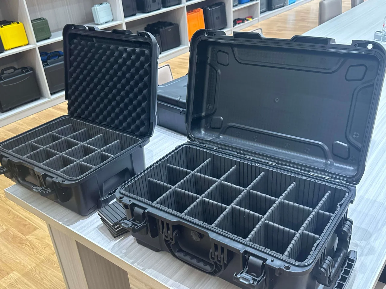
One point that is repeatedly missed is the handling stage before packing. A transducer that has been set down on a bench with its acoustic face in contact with the surface has already been compromised, even if nothing appears to have happened. The recommended practice is to keep every transducer on a face-down stand that supports the flange rather than the window, and to move it only with the sleeve fitted. Personnel should wear lint-free gloves, because skin oils are a contaminant in their own right once they reach the acoustic window, and they leave no visible mark. Where a protective film is used, it should be a low-tack electrostatic PE film, and its model number and application date should be logged so the film can be traced if a sensitivity anomaly appears later. Ordinary pressure-sensitive tape is not acceptable, because the residue it leaves demands solvent cleaning, and the solvent is often more damaging to the acoustic window than the residue would have been.
Array Compartmentalization and Element Position Retention
An array is built from many elements arranged at a defined pitch, then either vulcanised as a whole or assembled mechanically. The relative positions of the elements determine beamforming accuracy directly. If elements are allowed to shift individually in transit, the directivity of the complete array can fall out of tolerance even when every individual element is perfectly intact.
The protection emphasis for an array is therefore global restraint with element-by-element location. First, locating blocks matched to the element outline clamp each element at its intended position. Those blocks are fixed to a common baseplate, so the array is constrained as a single rigid body. The baseplate is then connected to the case through a cushioning layer, which spreads impact loads across the whole array face rather than concentrating them on individual elements. Element pitch should be checked against the array drawing at the design stage of the liner, because a locating block machined to the nominal outline of an element with a moulding flash will grip on the flash and hold the element slightly off pitch.
For large arrays that cannot be cased as a single unit, sectioned packing is acceptable, but the section position and serial number of every section must be recorded, and protective caps must be fitted at the joints so the mating faces cannot be knocked. A sectioned array needs its element pitch and mating face flatness re-measured on arrival, and the acceptance clause should state the measurement method and permitted deviation. As a rule, relative element displacement is held within 0.5 mm and mating face misalignment within 0.3 mm. Lifting an array needs the same care: slings should pass around the array frame and never around the elements themselves, and the lifting angle should match the designed lifting points. Where array sections are swapped frequently, the modular logic of a removable divider and locating system allows the locating blocks to be made as changeable inserts, reconciling multi-model reuse with location accuracy.
Watertightness and Moisture Control: IP67 Sealing and Immersion Boundaries
Sonar equipment has an ambivalent relationship with water: it works in the water and it is at its most vulnerable to water during transport. The concern is not immersion as such, but immersion that nobody notices. The protection target for the case therefore has two layers. The first is full dust tightness and short-term immersion protection to IP67 (IEC 60529 / GB/T 4208), keeping the interior dry during loading in the rain, on a flooded deck, or after a brief fall into the water. The second is that any ingress should leave a readable trace, for example a humidity indicator card and water-sensitive labels inside the case, so the seal can be judged the moment the case is opened.
It needs to be stated clearly that the IP rating of the case and the watertight rating of the equipment are two different things. The equipment's watertightness is determined by the transducer's own sealing structure. The IP rating of the case only protects against accidental ingress from the transport environment; it does not substitute for the equipment's own watertightness. Where the route involves small boat transfer, deck lifting or a realistic chance of going overboard, IP68 can be selected, but the knock-on effects of increased case weight, harder opening and pressure equalization demand must be assessed at the same time. Seal material selection should prioritise seawater resistance, ozone resistance and UV resistance; silicone rubber and EPDM are the common choices, and the corresponding compression and hardness figures are set out in the comparison of seal material selection. The table below maps case protection grades to transport scenarios.
| Protection grade | Reference standard | Typical test condition | Applicable transport scenario | Items to consider at the same time |
|---|---|---|---|---|
| --- | --- | --- | --- | --- |
| IP65 | IEC 60529 / GB/T 4208 | Water jets with no harmful effect | Indoor transfer, covered vehicles | Not suitable for open deck storage |
| IP66 | IEC 60529 / GB/T 4208 | Powerful water jets | Loading in rain, short exposure outdoors | Seal must be UV resistant |
| IP67 | IEC 60529 / GB/T 4208 | 1 m water depth for 30 min short immersion | Quay transfer, water on deck | Pressure equalization valve must be a waterproof breathable type |
| IP68 | IEC 60529 / GB/T 4208 | Continuous immersion (conditions agreed with maker) | Small boat transfer, possible overboard | Case weight and lifting method must be recalculated |
| Additional requirement | GB/T 10125 | Neutral salt fog 96 h or more | Long coastal and shipboard storage | Passivation of metal parts, galvanic isolation |
Marine Salt Fog Corrosion and Galvanic Isolation of Metal Parts
Corrosion at sea is not simply rust. It is salt fog, humidity, thermal cycling and galvanic effects acting together. Chloride ions in salt fog break down the passive film on metal surfaces, and stainless steel can suffer pitting and crevice corrosion in a chloride environment. When aluminium parts touch stainless steel parts directly, the resulting galvanic couple accelerates corrosion of the aluminium.
Protection works at three levels. At the material level, metal parts of the case should be 316 or 316L stainless steel where possible, with aluminium parts anodised and fitted with insulating washers as required. At the structural level, nylon or PTFE washers should be inserted between dissimilar metal contact surfaces to break the galvanic path, and anti-seize compound should be applied to bolted joints so threads do not seize after long storage. At the verification level, a neutral salt fog test to GB/T 10125 should show no functional corrosion of case metal parts and latches within 96 h.
Routine maintenance is part of corrosion protection. After every return to store from a voyage, the case surface should be rinsed with fresh water to remove salt deposits and then dried, with particular attention to the latches, hinges and the area around the pressure equalization valve, because these are where salt accumulates most readily and where it is hardest to wash out. The general practice for hinge and latch construction is described in hinge, latch and seal structures, but marine duty calls for the material grade to be raised by one step across the board. Where a case is stored on deck for long periods, the base should not rest directly on a steel deck that holds water; it should be raised on dunnage with ventilation maintained underneath.
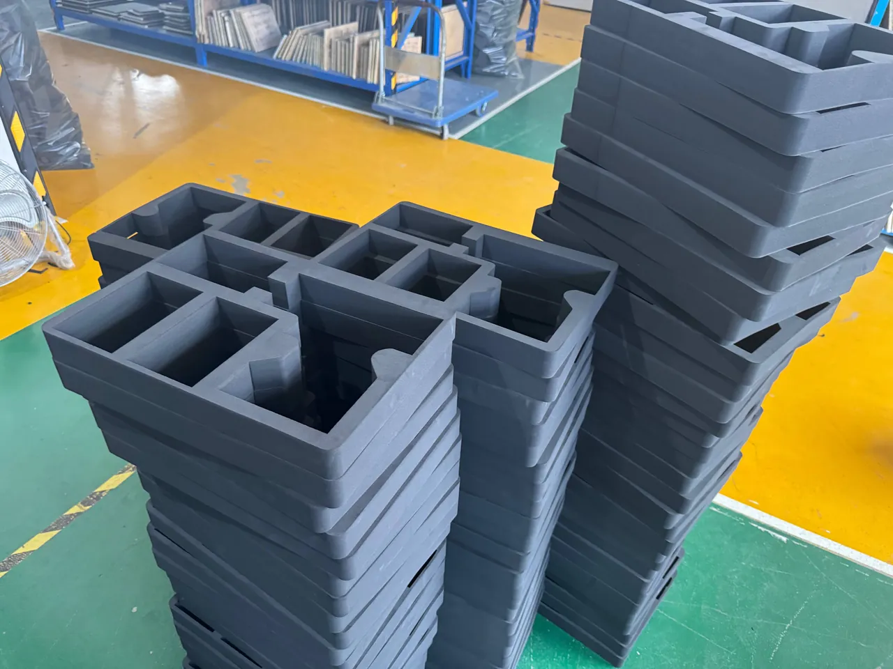
A second, less obvious corrosion path runs through the inside of the case. Desiccant that has become saturated, a liner that has absorbed salt water, or a soaked strap stored inside will all keep the interior humid and drive corrosion from within while the exterior looks perfect. The remedy is procedural: never store wet accessories in a sealed case, replace desiccant on a defined interval rather than on appearance, and record the indicator card reading at every opening so that a rising trend is visible before damage occurs.
Rack and Board Retention in Sonar Electronics Cabinet Units
Sonar electronics cabinet units are usually integrated in 19-inch rack form, containing signal processing boards, power amplifier modules, power supplies and a backplane. The biggest transport risk is not the enclosure being knocked; it is the microscopic reciprocating motion of boards inside their slots. Low-frequency vibration on a road journey lets a board creep slightly along its slot direction, and over time this produces gold finger wear, relaxation of the slot spring contacts and ultimately intermittent contact. These faults do not necessarily raise an alarm during power-on self-test, yet they appear randomly during at-sea operations.
The answer is dual restraint. Boards are first locked individually with the retaining bars or clamp plates supplied with the rack. The whole board set is then wrapped together with the rack in an ESD bag to keep dust and moisture out of the slots. Wire rope isolators or rubber isolation pads are fitted at all four corners of the cabinet, so the cabinet is elastically suspended relative to the case and vibration in the 5 to 20 Hz band is attenuated. Isolator selection must be calculated from cabinet weight and the number of mounting points, and after installation the cabinet should show a clear elastic rebound when pushed by hand.
The backplane and mother board should stay in place and must not be removed for weight saving and packed separately. A removed backplane is more vulnerable in its own packaging, and the alignment accuracy on reassembly is difficult to guarantee. Heavier modules such as amplifiers and power supplies should be positioned in the lower part of the rack to create a low centre of gravity. There must be no rigid connection between the cabinet and the case other than the isolators, because any such connection bypasses the isolation and renders it ineffective.
Desiccant and a humidity indicator card belong inside the case, and the cabinet should be wrapped in a moisture barrier film. The film should not be vacuumed, because external pressure would bear directly on the boards. On arrival, the first check is that every board retaining bar is in position, followed by a connector-by-connector confirmation that nothing has loosened.
Bend Radius and Stress Relief for Towed Cables and Connectors
The towed cable is the component most often taken for granted in a sonar system. It can look perfect on the outside while having a broken internal conductor or a flattened jacket, and it will then test good one day and bad the next. Cable damage comes from three sources: a winding radius that is too small, which creases the jacket and crushes the internal shield; the cable body being used as a load-bearing element and cinched tight with a strap; and force applied at the termination, which deforms the watertight structure.
The protection scheme follows three rules: the cable body carries no load, the ends are controlled, and coiling uses a large diameter. Use a drum or curved cradle whose diameter is not below the maker's limit. For towed array cables the empirical bend radius is usually not less than 20 times the cable diameter, although the maker's specification takes precedence and some thin or fibre-optic composite cables require more; ordinary signal cable can be relaxed to 10 times the diameter. The drum should have flanges at both ends to stop the layers sliding off, and soft interleaving sheets should be placed between layers to prevent layer-to-layer compression.
Terminations, especially watertight connectors, should be fitted with dedicated caps and placed in individual keyed positions with pins facing up, and desiccant should be placed inside the cap. The transition between cable and termination needs stress relief, achieved by securing the cable with a soft strap at a defined distance from the termination so that the pull is taken by the fixing point rather than by the connector.
Cable temperature behaviour also matters. Polyurethane jackets stiffen at low temperature and crack more readily when bent, so in winter the cable should be allowed to warm to room temperature before coiling, and it must never be forced to bend below the maker's minimum service temperature. On arrival, continuity and insulation resistance should be measured and the readings logged as a baseline for later fault diagnosis.
Low Outgassing and Cleanliness Control for Acoustic Materials and Acoustic Windows
Acoustic materials such as transparent rubber, polyurethane coatings and sound-absorbing backing are mostly polymers, and they release trace plasticisers and organic volatiles as temperature rises. These volatiles do not damage acoustic performance by themselves, but they accumulate inside a sealed case and condense on the acoustic window as an oily film that changes the acoustic boundary condition of the surface. Where transducers share a case with electronics, volatiles can also contaminate connector pins and gold fingers.
There are three control measures. The interior should have moderate ventilation or a pressure equalization valve so it is never fully sealed for long periods. Liner materials should be low-outgassing formulations, avoiding plasticiser-containing PVC foam. Acoustic windows with high cleanliness requirements should be covered with a low-tack protective film before packing, and the film removed immediately before installation.
Cleanliness control also covers particulate contamination. The acoustic face should be wiped with a lint-free cloth moistened with pure water and dried before packing, and silicone-oil-containing cleaners are prohibited. Liners must not use flocked materials or cardboard that sheds fibre. If a case has previously carried oil-bearing parts, it must be thoroughly cleaned and the liner replaced before it is used for acoustic items.
For components that will enter a cleanroom or go onto an acoustic test bench, the exterior of the case should be wiped before it crosses the threshold, so that quay dust is not carried into the test environment. In practice the most reliable approach is to dedicate cases to acoustic duty and never to lend them to general transport, because a single contaminated case in a batch will show up as an unexplained sensitivity anomaly that costs far more to investigate than the case itself.
Shock and Vibration Damping: Vibration Sensitivity of Transducers and Hydrophones
The piezoelectric ceramics inside transducers and hydrophones are brittle materials. They can withstand underwater acoustic pressure in service, yet they are highly sensitive to high-frequency shock and drop. The core of cushioning design is to control peak acceleration and avoid resonance.
Closed-cell EVA or PE foam with a density of 40 to 60 kg/m3 is commonly used as the first cushioning stage, with compression controlled between 10 and 20 percent. For heavier array sections, an additional independent elastomeric support block outside the foam forms a second isolation stage, so that impact energy is absorbed progressively across the two stages. The density of the foam is not the only variable: the loaded area and the thickness of the foam layer determine the natural frequency of the packed system, and a thin layer of dense foam behaves very differently from a thick layer of light foam even where the static deflection is the same.
Particular attention is needed because acoustic components usually have low natural frequencies. If the natural frequency of the cushioning system approaches the dominant frequency of transport vibration, the response is amplification rather than attenuation. The engineering approach is to prepare foam in two density grades and, after the first packing, to confirm by measurement that peak acceleration is within the permitted range by placing a shock and vibration recorder inside the case. The material density is then fixed. Drop verification heights are selected by component weight: 60 to 80 cm corner-and-edge drops for a single transducer, and 40 to 50 cm for heavy arrays and cabinets. These are engineering reference values and the final figure must be confirmed by measurement. The relevant test sequences can be designed against ISTA transport testing procedures and the ASTM D4169 distribution cycle. Density and resilience comparisons for cushioning materials are set out in the cushioning liner selection guide.
Case Body Material, Seals and Pressure Equalization Valve Selection
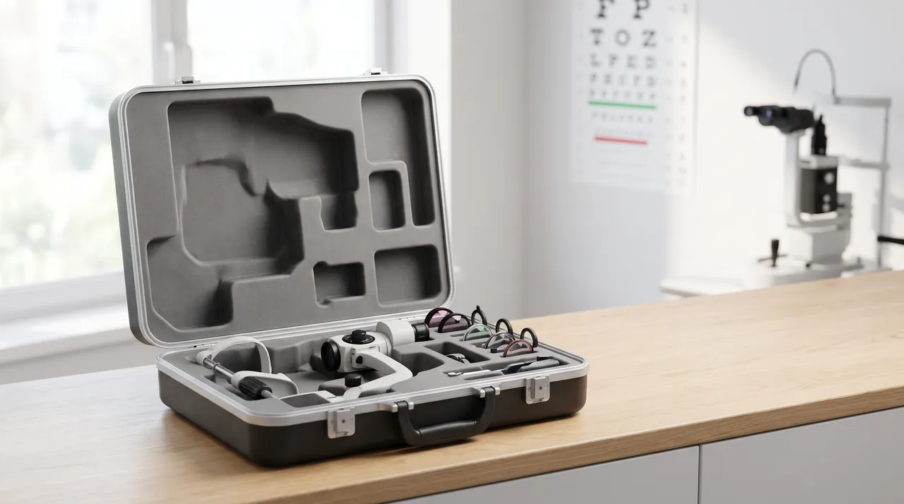
Case selection for a marine project has to satisfy three requirements at once: sealing, corrosion resistance and handleability. The case body should use modified PP or an ABS blend engineering plastic. Large array cases can use rotationally moulded LLDPE with an aluminium alloy frame to raise torsional stiffness. Every exposed metal part should be selected to the corrosion requirements in the salt fog section.
Seals should be silicone rubber or EPDM with 25 to 35 percent compression and a hardness of 50 to 60 Shore A, which is the common range. The cross-section of the seal groove must match the seal profile so it cannot roll over under compression. Where a case is opened and closed frequently at sea, a slightly lower compression with a deeper groove is more forgiving than a high-compression arrangement that demands perfect cleaning of the groove every time.
A pressure equalization valve is equally necessary in marine transport, but two aspects differ from land use. First, the valve must be a waterproof breathable type with a salt-fog-resistant membrane. The membrane in an ordinary breather valve clogs readily in a salt fog environment, producing a valve that lets air in but not out, or fails completely. Second, where the case will cycle between high deck temperatures and low hold temperatures, the air flow rate should be on the generous side, with an empirical value of 200 to 500 mL/min, and the desiccant quantity should be increased to compensate for the moisture exchanged. The valve should be mounted high on a side wall, clear of the load paths created by lifting and stacking and clear of the direct path of wash-down water. Wheeled cases used aboard ship should have their wheels locked and anti-slip pads fitted, so that vessel motion cannot make them travel.
Temperature, Humidity, Condensation and Desiccant Configuration
Condensation during sea transport is more severe than on land. A container bakes on deck by day and cools at night, so moisture inside the case condenses repeatedly. Acoustic components and electronics are both sensitive to this, and corrosion layers and connectors are more sensitive still. The control logic resembles general sea freight but the requirements are stricter: sealing, desiccant, humidity indicator card and temperature equalisation on arrival.
An empirical desiccant quantity is 80 to 120 g/m3, taking the upper figure for long routes or for voyages that call at high-humidity ports. The indicator card should be fixed in a position that is visible as soon as the case is opened, so it can be read without disturbing the contents. On arrival the case should not be opened immediately; it should be allowed to equalise in the store for 2 to 4 hours first, so that condensation does not form directly on acoustic faces and mating surfaces.
Desiccant selection should avoid calcium chloride types, because they can weep liquid after absorbing moisture and the weep will contaminate acoustic faces and electronics. Silica gel and montmorillonite types are comparatively safe and can be supplied in non-woven packaging to contain dust. Where a case contains rubber components, the interior should not be driven to absolute dryness, because rubber that loses water over long periods hardens and cracks; maintaining 30 to 50 percent RH is the more prudent band. After every opening, the indicator card colour and desiccant condition should be recorded and retained as part of the case status history. Over several voyages this record shows whether a seal is degrading long before a wet part is found.
Transport Compliance Testing and Acoustic Re-Test on Arrival
Transport verification is best run on two parallel lines: case level and component level. At case level, follow the GB/T 4857 series of transport packaging tests for stacking, vibration, drop and impact, confirming that the case, latches, seals and liner survive limit loads, and verify salt fog resistance to GB/T 10125. Environmental items can be selected using MIL-STD-810H methodology, noting that this standard is used only as a source of environmental test methods and does not imply any military certification; humidity, vibration, shock and salt fog methods are used to exercise the protection chain rather than the equipment's performance. At component level, loading trials with dummy weights before the liner is finalised verify the reliability of the locating features and the compression set of the foam.
The most important part of the acceptance stage is writing acoustic re-test into the contract. On arrival, visual and cleanliness checks come first, followed by acoustic re-test. Transducers are commonly checked by admittance or impedance measurement with sampling of free-field sensitivity; arrays add element consistency and directivity checks. The re-test values are compared with the factory baseline, and transport is judged acceptable when the deviation is within the agreed range. Where free-field conditions are unavailable, admittance curve comparison can be used as a screening method, with anomalous units sent to a laboratory for full testing. For sealing performance, the humidity indicator card, water-sensitive labels and the appearance of sealing faces should be checked on arrival, with a whole-case leak test performed where necessary.
| Test item | Reference standard | Suggested condition (typical value) | Judgement focus |
|---|---|---|---|
| --- | --- | --- | --- |
| Stacking | GB/T 4857.3 | Load converted from stacking height, 24 h | No permanent case deformation, liner recovers normally |
| Random vibration | GB/T 4857.23 / ASTM D4169 | One road spectrum and one sea spectrum | No cabinet board displacement, block locators still tight |
| Drop and impact | GB/T 4857.5 / ISTA 2A | Corner, edge and face once each, height by weight | No through-crush of the liner, no transducer anomaly |
| Salt fog | GB/T 10125 | Neutral salt fog 96 h | No pitting or galvanic corrosion of metal parts |
| Damp heat | MIL-STD-810H Method 507 | High temperature and humidity cycling | No condensation inside, acoustic face uncontaminated |
| Immersion | IEC 60529 / GB/T 4208 | IP67 short immersion (or agreed IP68 conditions) | No water traces inside, indicator card unchanged |
Sea Freight, Lifting and Stacking Markings
The biggest difference between shipping by sea and moving by road is six degrees of freedom. Roll and pitch make inadequately restrained contents travel back and forth inside the case, and even a small amplitude will cause wear once it accumulates over days. A restraint review before shipment is therefore mandatory: fill all cavity clearances with soft foam, re-check strap tension, and secure every removable item such as caps, locating blocks and tool kits individually. Cases should be positioned away from hatch openings and the wave-exposed side of the ship, raised on dunnage to prevent water ingress from below, and kept clear of the load paths of mooring lines and lashing chains.
For lifting, the lifting points of the case must align with its structural load path. Use sleeved slings and keep the lifting angle within 60 degrees. Deck lifting at sea is affected by vessel motion, so a tag line is recommended to control swing, and personnel must never work beneath a suspended case. Markings follow GB/T 191 and GB/T 13384 and should at minimum include this way up, keep dry, fragile, centre of gravity and lifting points, together with case number, part number, net weight and gross weight. Cases containing acoustic components should carry an additional marking reading acoustic face, do not compress, with the direction stated, so handling staff can identify it. Wheeled cases should have wheels locked and anti-slip pads fitted aboard ship, and when stored on deck they should be lashed to the vessel structure.
Case Rotation, Cleaning and Spares Management for Marine Projects
Cases on marine projects often stay with a vessel for years, and the quality of the return-to-store cleaning routine determines how well they protect the next voyage. The routine should be fixed: read and record the humidity indicator card immediately on opening; remove the components and inspect acoustic faces and connectors for contamination; rinse salt from the case exterior with fresh water and dry it, concentrating on the seal groove, latches and the area around the equalization valve; check the seal for hardening, cracking and permanent compression set; check hinges for looseness and latches for correct spring force; confirm there is no residual oil inside, dry the case and close it. The cleaning method can follow the standard process for protective case cleaning and care, but marine duty calls for more frequent fresh water rinsing and drying.
Spares management for marine projects has one specific requirement. Because transducers and cable terminations have long repair turnaround times, stock is usually held in advance, so the number of cases, liner serial numbers and the spares ledger must correspond one to one; otherwise a case is held without the part it was built for, or a part is held without its case. JUNZHIJIA supplies liner numbering drawings, case packing lists and status record cards keyed to model for marine acoustic projects, supports OEM and ODM branding, supplies seals and spares kits by model, and can issue transport test reports and material declarations against customer-specified standards such as GB/T 4857, ISTA, ASTM D4169 or MIL-STD-810H methods, so that transport protection can be brought into the equipment quality record system. Cases that are cycled frequently and stored in poor conditions should have an annual seal check and a liner compression set inspection; the economic service life of a protective case is usually estimated at 5 to 8 years, but a condition-based judgement is more sound, and the method is described in protective case service life assessment.
FAQ
Q: Can the acoustic face of a transducer be covered with a protective film or wrapped with protective tape?
A: A low-tack protective film is acceptable, but ordinary tape is not. A low-tack film such as an electrostatic PE film blocks dust and light abrasion without leaving residue, and it is simply peeled off before installation. The problem with ordinary pressure-sensitive tape is that its residue cannot be fully removed, and the remaining adhesive layer creates a local acoustic impedance discontinuity that appears as anomalous sensitivity or directivity during acoustic re-test. Removing that residue usually requires a solvent, and the solvent is often more aggressive towards the acoustic window than the residue was. The correct arrangement is a three-layer protection scheme: a low-tack film directly on the acoustic face, a powder-free soft sleeve over it, and a relieved cavity in the liner so the face is fully suspended. Where surface cleanliness requirements are very high, a lint-free cloth can be added inside the sleeve. Every application should be carried out on a clean bench, and fingers should not touch the radiating face, because skin oils are a contaminant in their own right. Record the film model and the application date before packing so the history is traceable.
Q: Should the case for sonar equipment be rated IP67 or IP68?
A: It depends on the transport scenario, not on the watertight rating of the equipment itself. IP67 covers full dust tightness and short immersion at 1 m depth for 30 minutes, which is enough for loading in rain, water standing on a quay and spray on deck. IP68 suits small boat transfer, a realistic chance of going overboard, or long periods of open deck storage, but its test conditions are agreed with the manufacturer, so selection must establish the specific depth and duration rather than relying on the IP68 label alone. A frequently overlooked knock-on effect is weight and opening effort. An IP68 case usually has thicker walls and stronger latches, so the higher dead weight changes lifting and manual handling arrangements and opening demands a larger instantaneous force. Where the equipment is humidity sensitive, the pressure equalization valve arrangement must be assessed at the same time, because a fully sealed heavy case breathes harder and equalises more slowly. In practice, list the worst-case condition for each segment of the route, set the grade from that worst case, and raise the seal material to seawater and UV resistant grades at the same time.
Q: Can an array be packed in sections, and does sectioning affect acoustic performance?
A: Sectioning is acceptable, but it requires a traceable rule covering both sectioning and reassembly. In a mechanically assembled array, each section's elements and frame are independent, so they do not interact in transit. The risk lies in two places. The first is the mating faces, meaning locating pin holes and coupling flanges, which can be knocked in transit and cause misalignment on reassembly. The second is confused section numbering, which leads to sections being reinstalled in the wrong order. The practice is to fit a protective cap on every mating face, restrain each section individually, include a section numbering drawing in the case, and on arrival measure element pitch and mating face flatness, holding the deviations within 0.5 mm and 0.3 mm respectively as typical values, with the design tolerance taking precedence. A fully vulcanised monolithic array should not be sectioned, because sectioning means cutting or destroying the vulcanised structure, which is irreversible damage rather than packing. The sectioning scheme should be written into the technical agreement so that the boundary of responsibility is explicit.
Q: Why do sonar electronics cabinet units need vibration isolators, and why is ordinary foam not enough?
A: Foam absorbs shock, while isolators attenuate sustained vibration; they work in different frequency bands and neither can replace the other. The boards inside a cabinet are most vulnerable to sustained low-frequency vibration in the 5 to 20 Hz band, which is exactly where road transport and sea-state motion concentrate their energy, and it is also the band in which foam is practically transparent, neither damping nor isolating. Wire rope isolators and rubber isolation pads are designed for that band. In engineering practice the two are combined: isolators at the four corners of the cabinet create an elastic suspension, and remaining space between the cabinet and the case is filled with foam to prevent impact against the shell. The critical point is that the isolators must not be bypassed by a rigid connection. There must be no direct bolt or support contact between the cabinet and the case, or vibration will be transmitted along the rigid path and the isolation will be wasted. Isolator selection is calculated from cabinet weight and mounting point count, and after installation a hand push should produce a clear elastic rebound.
Q: How is the bend radius for a towed cable determined, and what coiling diameter is appropriate?
A: Take the maker's specification as authoritative, fall back on the empirical formula only when the specification is silent, and always leave a safety margin. Towed array cables and composite cables containing optical fibre are the most sensitive to bending; the empirical value is usually not less than 20 times the cable diameter, and some thin or fibre-optic cables demand more. Ordinary signal and power cables can be relaxed to 10 times the diameter. Beyond the radius, two limits are frequently overlooked. The first is the number of coiled layers, because excessive layer-to-layer pressure flattens the jacket, so single-layer or few-layer coiling with interleaving sheets is recommended. The second is temperature, because polyurethane jackets stiffen in the cold; in winter the cable should be warmed before coiling and must never be forced to bend below the maker's minimum service temperature. Continuity and insulation resistance should be measured on arrival and the readings archived as a baseline for later fault diagnosis. Where a cable has clearly been crushed, the external condition should be recorded even if the measurements are normal, because jacket damage can take months to develop into an electrical fault.
Q: How is salt fog corrosion prevented on the case, and what should be checked at acceptance?
A: Protection rests on three steps: material, isolation and maintenance. For material, metal parts of the case should preferably be 316 or 316L stainless steel, with aluminium parts anodised. For isolation, nylon or PTFE washers should separate dissimilar metal contact surfaces and bolts should be coated with anti-seize compound, breaking the galvanic corrosion path. For maintenance, the case should be rinsed free of salt and dried after every return from a voyage, with particular attention to latches, hinges and the area around the equalization valve. At acceptance, a neutral salt fog test to GB/T 10125 is recommended, and within 96 hours metal parts and latches should show no functional corrosion and no pitting, while plated layers should be checked for blistering and flaking. A simple and effective routine check is to look for white or green salt crystals in the gaps around latches and hinges; their presence means cleaning has been inadequate. For cases stored on deck for long periods, raising the base on dunnage and maintaining ventilation is more effective than any coating, because it removes the standing water that drives the corrosion reaction in the first place.
Q: Is acoustic re-test really necessary on arrival, and which items should be measured?
A: It is strongly recommended, and the re-test values should be entered into the transport record together with the factory baseline. The most economical screening method for a transducer is admittance or impedance measurement using a portable impedance analyser to read resonant frequency, resonant impedance and capacitance, compared against factory values. This detects most anomalies including ceramic stack cracking, water ingress and acoustic face damage. Where conditions allow, free-field sensitivity sampling and a directivity check should be added, and arrays should additionally be checked for element consistency and mating face flatness. The logic behind the sequence is that small changes in acoustic performance usually have an electrical precursor, and an admittance curve shift typically appears before sensitivity exceeds tolerance. Re-test should be performed after the item has stabilised at room temperature, because a temperature difference produces measurement drift that can be mistaken for damage. Where free-field conditions are unavailable, admittance comparison serves as a screening method, with anomalous units sent to a laboratory for full characterisation.
Q: What can JUNZHIJIA provide for sonar and marine acoustics projects?
A: For transducers, arrays, electronics cabinets and towed cable terminations, JUNZHIJIA provides a complete package from liner design through to delivery documents. On structure and liner, cavities are designed from the customer's 3D model to suspend the acoustic face, together with array compartment locating blocks, cabinet isolator mounting positions and cable drum retention features, using ESD or seawater-resistant formulations as required. On the case itself, modified PP, ABS and rotationally moulded LLDPE body options are available with 316 stainless steel hardware, waterproof breathable pressure equalization valves and seawater-resistant seals. Documentation can include liner drawings and material lists, sealing grade and compression statements, transport test reports compiled to GB/T 4857, ISTA or ASTM D4169, GB/T 10125 salt fog verification summaries, packing lists and liner numbering drawings. The company also supports OEM and ODM branding, supplies seals and spares kits matched to equipment model, and can advise whether a project justifies a dedicated mould or a platform approach pairing standard case bodies with changeable liners.
Conclusion and Further Reading
Sonar transducer transport protection cuts three irreversible loss chains: the acoustic face stays suspended; the watertight structure relies on impact protection and readable ingress traces; and metal parts resist salt fog through grade and galvanic isolation.
Related Reading