

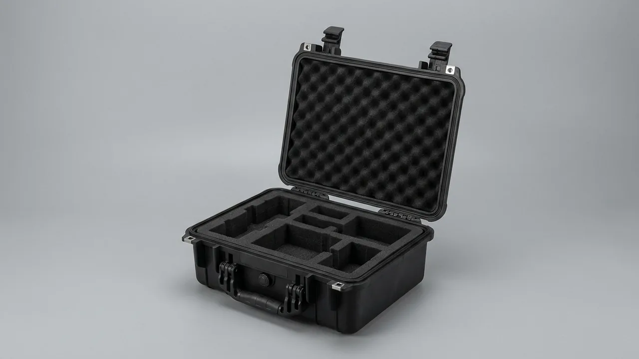
A meteorological station case is not simply a container that holds instruments. It is a transport, relocation and storage protection system built for unattended field sites. The conclusion up front: most weather station failures are not caused by sensors wearing out, but by moisture ingress, probe contamination, connector deformation and micro-vibration damage to data logger circuit boards during transport and redeployment. A compliant case must therefore combine IP67-class rain and moisture defence, probe-level protection against contamination and impact, a separately load-bearing compartment for the solar power module, and vibration and static-dissipative mounting for the data logger and communication module. Comparing wall thickness alone tells you very little. What actually determines the repair rate is the seal architecture, the geometry of the insert, and the order in which equipment is packed and retrieved.
The logistics chain behind a weather station is unusually punishing. An island site may involve sea freight plus crane lifts; an alpine site may be reached by cable way and then carried on foot; a desert site means long-distance off-road driving. Before a single data logger reaches its site it may have absorbed dozens of cumulative vibration events, two or more sharp temperature and humidity transitions, and at least one episode of driving rain. This article breaks the equipment down by component, states the vulnerability of each item, and gives concrete parameters for case structure, insert material, sealing and desiccation. It closes with a purchase specification template and an acceptance workflow that meteorology, hydrology, environmental monitoring, solar and agricultural weather programmes can quote directly.
Table of Contents
- Why Meteorological Stations Demand More From a Case Than Ordinary Industrial Enclosures
- Equipment Inventory and Vulnerability Grading for a Weather Station Case
- Rain and Moisture Defence in the Field: What IP67 Actually Requires
- Keeping Sensor Probes Clean and Unbruised: From Humidity Probes to Pyranometers
- Securing Anemometers, Wind Vanes and Booms
- Vibration and ESD Protection for Data Loggers and Communication Modules
- Protecting the Solar Power Module While Keeping It Easy to Reach
- Insert Materials Compared: EVA, EPE and XLPE for Field Weather Stations
- Case Hardware: Hinges, Latches, Seals and the Pressure Equalisation Valve
- Environmental Test Evidence: IP, Drop, Vibration, Salt Fog and UV
- Six-Step Field Workflow: Unpack, Deploy, Repack, Seal
- Parameters to Fix in the Purchase Specification
- OEM/ODM Supply and Batch Quality Control
- Frequently Asked Questions
- Conclusion and Further Reading
Why Meteorological Stations Demand More From a Case Than Ordinary Industrial Enclosures
An ordinary industrial instrument case usually serves a short chain: workshop to workshop, or warehouse to laboratory. A weather station case serves a long chain with multiple transport modes and almost no support infrastructure. Understanding that difference is the first selection decision.
First, the environmental span is enormous. A single national observation network may include a plateau site at -40 degrees Celsius and an island site where the case interior reaches +70 degrees Celsius in direct sun. If a seal material loses its elasticity at -40 degrees Celsius it will never recover its original compression set when temperatures rise, and the case quietly degrades from IP67 to splash-resistant only. That degradation does not show up on the day it happens; it shows up in the second rainy season.
Second, probes are semi-exposed precision components. The PTFE membrane on a temperature and humidity probe, the glass dome of a pyranometer, and the ceramic transducer of an ultrasonic anemometer cannot simply be wrapped and compressed. They need suspended support and local retention, not the face pressure you would apply to a machined steel flange.
Third, the accessory count is high and the form factors are scattered. A complete station includes sensors, a data logger, a communication module, a solar panel, a charge controller, a battery, masts and booms, and harnessed cable runs. Dimensions span two orders of magnitude, from a 20 mm connector to a 1.2 m boom. A single cavity cannot serve all of them, so the interior must be zoned. Compatibility questions between seal compounds and site chemistry are covered in seal material selection and compatibility.
Fourth, there is no repair capability on site. Field stations rarely have a clean bench, a temperature-controlled room, or spare parts. Any latent damage created inside the case is only discovered at the next annual inspection, and by then the cost is a gap in the observation series.
Fifth, corrosion and ultraviolet radiation are long-term killers. Coastal stations face salt fog, plateau stations face intense UV, and industrial-zone stations face acidic deposition. Hinges, latches and pressure equalisation valves, where metal meets polymer, fail first.
A useful rule of thumb: if a case passes an ordinary industrial drop test but cannot survive 16 hours at -40 degrees Celsius followed by another immersion test, it is not suitable for a weather station.
Equipment Inventory and Vulnerability Grading for a Weather Station Case
Different instruments fail through different mechanisms, so the case layout must be graded by consequence of failure multiplied by difficulty of repair, not by evenly distributing cushioning according to weight.
| Equipment category | Typical form and mass | Primary vulnerability | Protection priority | Insert form |
|---|---|---|---|---|
| --- | --- | --- | --- | --- |
| Temperature and humidity probe | Cylindrical probe plus radiation shield, 0.5 to 2 kg | PTFE membrane crushed, filter element contaminated | Suspended support, contamination control, moisture control | Closed-cell EVA compartment plus circular slot |
| Anemometer and wind vane | Cup assembly and tail fin, 1 to 3 kg | Cups deformed, thin tail fin bent | Three-point support, impact isolation | Cylindrical cavity plus dedicated fin slot |
| Barometric pressure sensor | Compact housing, 0.3 to 1 kg | Threaded port damaged, diaphragm shock loaded | Port facing up, ESD control | Carved EVA slot |
| Pyranometer | Dome plus body, 1 to 4 kg | Glass or quartz dome cracked, optical surface contaminated | Dome suspended, no face contact permitted | Ring support seat plus dome cavity |
| Tipping bucket rain gauge | Funnel plus bucket mechanism, 2 to 5 kg | Funnel rim deformed, bucket pivot displaced | Full retention, tip-over prevention | Full base contact plus lateral stops |
| Data logger | Metal or polymer enclosure, 1 to 4 kg | Board micro-vibration, connector strain, ESD | Vibration, ESD, moisture | Static-dissipative EVA plus silicone corner pads |
| Communication module | Module plus antenna, 0.5 to 2 kg | Antenna port loosened, RF connector damaged | Port protection, dedicated location | EVA slot plus cap storage cavity |
| Solar panel and controller | Thin panel, 3 to 15 kg | Micro-cracking, chipped edges, local point loading | Edge-borne support, glass face left free | Edge support strips plus isolation spacer |
| Battery | Rectangular block, 5 to 30 kg | Electrolyte leakage, terminal strain, case swelling | Dedicated load-bearing cavity, spill containment | Base plate plus retaining blocks |
| Cable and connectors | Bundled runs | Bending radius too small, pins deformed | Large-radius coiling, pin shrouds | Cable trough plus compartmented bags |
The grading principle is simple. Grade one items, which include domes, ceramic transducers and optical surfaces, must never be in face contact under pressure. Grade two items, such as circuit boards and connectors, may be in face contact but must be positively located. Grade three items, meaning metal rods and structural housings, may be pressed directly. Shifting cushioning budget away from grade three items and into suspended architecture for grade one items is the single most cost-effective protection upgrade available. The full customisation route is described in EVA foam insert customisation process.
Rain and Moisture Defence in the Field: What IP67 Actually Requires
Under IEC 60529 and its national equivalents, IP67 means fully dust-tight plus no harmful water ingress after 30 minutes of immersion at one metre depth under standard conditions. The important caveat is that IP67 is a one-time verification result, not a permanent operating state. Seals age, housings degrade under ultraviolet light, and latches wear through repeated cycling. Real protection is a function of time.
Field moisture defence for a weather station case relies on three stacked barriers.
- The housing seal barrier. Main gasket compounds are typically silicone, EPDM and TPU. Silicone retains elasticity down to about -50 degrees Celsius and has low compression set, making it the first choice for cold plateau sites. EPDM has better UV and weathering resistance and suits coastal and high-altitude deployments. TPU offers the highest mechanical strength but performs worse than silicone at low temperature. Gasket groove compression should be held between 25 and 35 percent; lower than that and the seal is not loaded, higher and permanent set accelerates.
- The inner moisture barrier. Instruments still exchange moisture with residual air inside the case. The standard practice is to place precision items into aluminium-laminate vacuum bags with a humidity indicator card before loading. Even if the outer seal degrades, the inner barrier maintains a dry environment.
- Desiccant and pressure equalisation. Size the desiccant by free volume. A typical working figure for montmorillonite clay is 50 to 100 grams per 30 to 50 litres of free volume, with silica gel slightly lower. At the same time a pressure equalisation valve is mandatory, because altitude change on a mountain route and day-night temperature swings otherwise create negative pressure inside the case, drawing moist air past the gasket and flattening the gasket against the groove so it cannot recover.
Two details are routinely overlooked. The first is condensation at the moment of opening. Carrying a case from -20 degrees Celsius into a +20 degrees Celsius room and opening it immediately causes instant condensation on every cold surface, and that does far more damage than a rain shower. The correct practice is to let the case stabilise for four to eight hours in a closed space before opening. The second is that the insert must not absorb water. Open-cell sponge behaves like a reservoir in humid conditions, so closed-cell material is required. For a wider treatment of the standard and its structural implications, see IP67 protective case structure and verification.
Keeping Sensor Probes Clean and Unbruised: From Humidity Probes to Pyranometers
Probe damage is rarely caused by a drop. It is caused by abrasion and contamination. Dust, oil mist, hand perspiration and fragments of crumbly foam can all permanently shift a sensor response curve, and such damage is typically only discovered during recalibration.
Temperature and humidity probes. The outer PTFE membrane or sintered stainless filter is the protective layer, yet it is highly vulnerable to lateral compression. The insert should provide a cylindrical slot roughly 0.5 to 1 mm larger than the probe diameter, so the probe is radially located without being gripped. Do not use foam with raised nubs to press the probe down, and do not place probes in the same cavity as metal hardware.
Pyranometers. The dome is the most brittle glass component in the whole station. When packing, leave at least 5 mm of clearance around the dome and let the body flange or a ring support seat carry the load. Any cushion resting directly on the dome is a design error. Fit a polyethylene protective cap before packing and keep spare caps inside the case.
Ultrasonic anemometer transducers. Ceramic transducers are extremely sensitive to point impact. Mount the complete assembly in its own cavity with closed-cell EVA walls, and ensure transducers never touch one another. Where the transducer arms are detachable, pack the arms separately so they cannot act as levers inside the case.
Three practical contamination rules:
- Use only closed-cell insert materials, preferably EVA at 38 kg per cubic metre or denser, to minimise shedding.
- Wipe optical surfaces and membranes with a lint-free cloth and anhydrous ethanol before packing, and allow full evaporation before fitting caps.
- Keep paper labels and cardboard out of the case, because damp paper becomes a contamination source.
Three practical impact rules:
- Give grade one items their own cavity with at least 10 mm of solid wall between cavities.
- Leave 5 to 10 mm of axial travel so the probe can absorb axial shock.
- Add a soft compression pad on the lid side so the closed case forms a compliant contact rather than a hard stop.
Securing Anemometers, Wind Vanes and Booms
Cup anemometers and wind vanes are classic thin-walled cantilever assemblies, and that mechanical character means cushioning cannot be designed as uniform compression.
Cup assemblies. Three or four hemispherical cups are joined to a central shaft by slender arms. Bending any one arm introduces a wind speed bias that appears as a systematic error on a calibration bench and is easily misdiagnosed as sensor ageing. The recommended solution is a full cylindrical cavity with three-point compliant support: the cavity accommodates the whole cup set axially, while three support points contact the lower shaft end and the roots of two arms, routing impact force into the strongest part of the structure.
Wind vanes. The tail fin is a thin plate and has the lowest bending resistance in the assembly. Provide a shallow contour slot matched to the fin profile, with a depth of 1.5 to 2 times the fin thickness, so the fin lies in the slot rather than being clamped by it.
Booms and mast sections. Rods longer than 800 mm should not share a layer with precision instruments. The correct approach is to mount them on an external rack or in a separate long case, keeping only sensors and electronics inside the main case. Where they must travel together, run the rods along the long axis of the case, retain them with half-round cradles and straps, and leave cushioning clearance at both ends.
Carrying on foot and lifting. The last leg of the journey to an alpine or island site often has no machinery. The case design must then deliver three things: a sensible centre of gravity, ideally at 40 to 45 percent of case height; a handle rated for at least twice the fully loaded mass; and metal inserts for shoulder straps or lifting rings. These features must be designed into the mould; they cannot be retrofitted.
Vibration and ESD Protection for Data Loggers and Communication Modules
The data logger is the brain of the station. Its failure interrupts the entire observation series, so it receives the highest protection level inside the case.
Vibration design. Measured peak acceleration in off-road transport commonly falls in the 5 to 15 G range depending on road condition and packaging level. A data logger typically weighs 1 to 4 kg, which makes it a medium-mass, low-natural-frequency item prone to resonance amplification with the case and vehicle. Fit silicone damper pads at all four corners, then seat the assembly in a carved EVA slot to create two-stage isolation. Simply wrapping the logger in thick foam is a common mistake: under high acceleration the foam compresses to its dense state, isolation disappears, and shock transfers straight into the housing.
ESD design. Inside the logger housing there are exposed boards and CMOS devices, and a human body discharge can cause latent damage that only surfaces later. Following the logic of IEC 61340-5-1 and ANSI/ESD S541, insert surfaces that contact the equipment should have a surface resistance in the 10⁴ to 10⁹ ohm range, providing static dissipation rather than insulation. Two mistakes are common in practice: plain foam, which is an insulator that accumulates charge and then discharges it into a board; and metal foil or mesh, which discharges too fast and too hard. See ESD-shielded case and insert design for the design approach.
Communication modules. RF connectors such as type N and SMA are fragile points, and a bent pin cannot be repaired in the field. Fit protective caps during transport and provide a dedicated storage slot for those caps next to the module so they are not lost. Detachable whip antennas should be coiled and restrained separately, never left free to swing.
Batteries. If the site uses lithium cells, UN 38.3 transport testing applies and the outer packaging must carry the corresponding lithium battery handling marks. Lead-acid batteries require spill containment: a load-bearing base plate with a containment lip, insulated terminal caps, and an absolute prohibition on inverted loading.
Protecting the Solar Power Module While Keeping It Easy to Reach
Solar power is standard on field stations and is the hardest element to pack. A 100 W class panel can exceed 0.6 square metres while being only a few millimetres thick, giving it very low stiffness.
How to carry a photovoltaic panel. The correct principle is edge-borne support with a free glass face. The frame or support strips carry the panel on all four sides, and a 3 to 5 mm gap is maintained between the glass and the insert. Never apply face pressure. Face pressure concentrates stress just inside the frame and produces micro-cracks that are invisible to the eye; those cracks propagate through outdoor thermal cycling and eventually show up as whole-panel power loss.
Zoning the controller and battery. A battery typically weighs five to ten times more than a data logger, so it belongs in a dedicated cavity near the base of the case and directly beneath the handle, which lowers the overall centre of gravity. The charge controller can sit above the battery, but a divider should separate them so battery venting cannot corrode the controller board.
Design logic for easy retrieval. Battery replacement is the most frequent field task, and a case that requires dismantling the whole insert layer each time is impractical no matter how strong it is. Three structures work well:
- Slide-out tray: the battery sits on a tray with runners and slides out once the case is open.
- Side access door: a small independent door on one side allows battery access without disturbing other compartments.
- Layered stacking: panel and mounting hardware on top, battery at the bottom, producing an unambiguous retrieval order.
That order should be printed on a card inside the lid: remove the light, bulky panel and booms first, then the precision sensors, and the heavy battery last. Repacking reverses the sequence. This alone measurably reduces impact damage to precision items during handling. Where sites relocate frequently, a removable divider system lets the interior adapt as the equipment inventory changes.
Insert Materials Compared: EVA, EPE and XLPE for Field Weather Stations
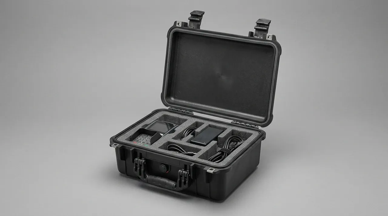
A weather station case insert is usually a combination of two to four materials rather than one material throughout. The selection logic allocates material by vulnerability grade, not by uniform cost optimisation.
| Material | Typical density | Resilience | Low-temperature behaviour | Shedding tendency | Typical use in weather station cases |
|---|---|---|---|---|---|
| --- | --- | --- | --- | --- | --- |
| EVA, closed cell | 38 to 80 kg/m³ | Good, high recovery after repeated compression | Good, flexible at -40 C | Low | Probe slots, logger slots, precision compartments |
| EPE pearl foam | 20 to 35 kg/m³ | Moderate, collapses after repeated impact | Moderate | Low | Wall padding, large-volume fill |
| XLPE, chemically cross-linked | 25 to 45 kg/m³ | Moderate, good fatigue resistance | Good | Low | Base cushioning for long-term storage cases |
| PU open-cell sponge | 20 to 40 kg/m³ | Good | Poor, hardens when cold | High | Not recommended near optical parts |
| Aluminium foil laminate | Not applicable | Not applicable | Good | Low | Moisture barrier, light block |
A recommended layered build:
- Base layer: 15 to 25 mm XLPE or high-density EVA sheet, absorbing the bulk of impact energy.
- Middle layer: carved EVA body providing retention and compartmentalisation.
- Surface layer: thin soft EVA or brushed fabric to prevent surface scratching.
- Corners: silicone damper pads for the data logger and communication modules.
- Moisture barrier: aluminium laminate layer or a separate vacuum bag.
One warning worth repeating: carved inserts do not hold their original dimensions indefinitely. EVA typically shrinks 2 to 5 percent after repeated compression, so slots loosen over the service life. Drawings should state a slot tolerance of plus or minus 0.5 mm with a permitted 3 percent compensation, and acceptance should include a physical fit check with the actual instrument rather than caliper measurement alone. A broader comparison framework is given in case insert material comparison.
Case Hardware: Hinges, Latches, Seals and the Pressure Equalisation Valve
Case reliability comes down to four interfaces, and these are exactly the places where low-cost proposals cut content.
Hinges. Weather station cases are opened and closed in cold weather, and ordinary polymer hinges crack under repeated load below -30 degrees Celsius. Choose stainless steel pins in a recessed design so the hinge stays within the case profile even at 180 degrees of lid travel, which reduces transport loading. The gasket near a hinge is easily pinched, creating a water path, so the hinge seat needs its own relief groove.
Latches. Vibration in field transport can pop a single-action latch open. Specify dual-action press-to-release latches that require two distinct movements, with an anti-accidental-release feature. Latch count follows case length, typically one every 250 to 350 mm, positioned so that gasket loading stays even.
Gaskets. Choose a replaceable push-in or adhesive-backed gasket rather than one co-moulded into the shell. A co-moulded gasket that ages condemns the whole case. Position the gasket joint at the middle of a long side rather than at a corner, because corners carry the highest stress and are the first place to lift.
Pressure equalisation valve. As noted earlier, a pressure equalisation valve is essential for mountain routes and air freight. It uses a hydrophobic breathable membrane to allow gas exchange while blocking liquid water, and it keeps the differential pressure within what the gasket can tolerate. The membrane has its own service life, so plan replacement every three to five years and add it to the annual inspection checklist.
Environmental Test Evidence: IP, Drop, Vibration, Salt Fog and UV
Verification should combine tests that match the deployment scenario rather than a single immersion check.
| Test | Common reference | Parameter basis for weather stations | What to watch |
|---|---|---|---|
| --- | --- | --- | --- |
| Ingress protection | IEC 60529 | IP67, or IP68 for exposed outdoor models | Gasket compression and recovery after immersion |
| Drop | ISTA series, ASTM D4169 | Alternating corner and edge drops | Case corners, hinge seats, latch seats |
| Vibration | GB/T 4857 series | Random vibration simulating off-road transport | Insert slot wear, fastener loosening |
| Stacking and compression | GB/T 4857 stacking clauses | 24 hours at rated load | Sidewall bulge, gasket flattening |
| Salt fog | GB/T 10125 | Neutral salt fog cycles for coastal sites | Hinge, latch and screw corrosion |
| Low temperature | Environmental test method reference | Soak at -40 C, then cycling and immersion | Gasket elasticity, material embrittlement |
| UV ageing | Xenon arc or UV chamber | High-insolation plateau and island sites | Shell chalking and colour shift |
| Static dissipation | IEC 61340-5-1 framework | Insert surface resistance 10⁴ to 10⁹ ohm | Logger and communication module protection |
One clarification matters commercially. MIL-STD-810H may be used as an environmental test method reference to define drop heights, temperature cycling profiles and vibration spectra, but it does not mean the product holds a military certification. Writing "test methods per MIL-STD-810H, not a military certification" in a specification is both accurate and defensible. See MIL-STD-810H and case environmental testing for the wording that survives procurement review. Sequential transport packaging validation is described in ISTA transport testing procedure.
Six-Step Field Workflow: Unpack, Deploy, Repack, Seal
Step one: inventory before arrival. Do not open the case in the transport vehicle or temporary camp. Verify the external label and the tamper seal only. The outside should carry the handling pictorials required for shipping marks, covering keep dry, this way up, keep away from heat, and stacking limit.
Step two: temperature equalisation. If the case temperature differs from ambient by more than 15 degrees Celsius, let it stand in a closed space for four to eight hours before opening. This single step prevents cold-surface condensation.
Step three: unpack in order. After releasing the latches, first inspect for water droplets and check the humidity indicator card. Remove items in the order light upper layer, precision middle layer, heavy lower layer, placing each item immediately onto a pre-laid soft mat rather than the ground.
Step four: inspect probes and optics. Check every membrane for tears, every dome for cracks, and every connector for deformation. Record and photograph any anomaly on site rather than opening the instrument for repair.
Step five: repack. Replace the desiccant, replace the humidity indicator card, and re-evacuate the vacuum bags before repacking. Accessories must return to their original slots; improvisation is not acceptable.
Step six: seal and label. After closing all latches, confirm that no gasket is visible outside the parting line, then apply the transport label and the next inspection date. If lithium cells are included, mark the case accordingly.
Parameters to Fix in the Purchase Specification
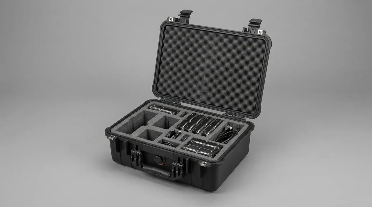
Writing the following parameters into the specification removes most later disputes and rework.
| No. | Parameter | Suggested wording |
|---|---|---|
| --- | --- | --- |
| 1 | Ingress protection | IP67 per IEC 60529 |
| 2 | Shell material | Copolymer polypropylene or equivalent weather-resistant engineering polymer with UV stabiliser |
| 3 | Gasket compound and replaceability | Silicone or EPDM, push-in type, fully replaceable |
| 4 | Operating temperature range | -40 C to +80 C, including low-temperature gasket elasticity requirement |
| 5 | Internal clear dimensions and layout | Zoning drawing plus an item list per zone |
| 6 | Insert material | Closed-cell EVA at 38 kg/m³ or denser plus XLPE base layer, with drawing and tolerances |
| 7 | Static dissipation | Insert surface resistance 10⁴ to 10⁹ ohm per the IEC 61340-5-1 framework |
| 8 | Pressure equalisation valve | Hydrophobic membrane type with rated service life and replacement interval |
| 9 | Desiccant configuration | Quantity by free volume, with humidity indicator card |
| 10 | Hardware | Stainless steel hinges and dual-action latches, with salt fog duration |
| 11 | Handling features | Handle rated at twice the loaded mass, with lifting ring or strap inserts |
| 12 | Marking and documents | Shipping pictorials, packing list, desiccant replacement record card |
| 13 | Acceptance rules | Sampling plan with AQL levels and defect classification |
Items seven and thirteen are the ones most often omitted, yet they directly determine the long-term reliability of the electronics. For the sampling logic behind batch acceptance, see custom case acceptance and AQL sampling.
OEM/ODM Supply and Batch Quality Control
Weather programmes usually buy against a fixed model with staged deliveries, from fifty to several hundred units per batch. Batch-to-batch variation deserves more attention than the quality of any single unit.
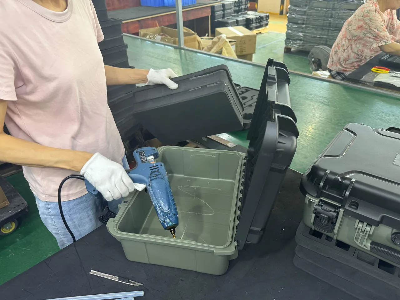
Drawing freeze and first-article approval. Three drawings should be frozen before tooling: the shell structure drawing, the insert zoning drawing, and the accessory list. First-article approval must include a physical fit check with the real instruments, especially probe slots and optical cavities, because drawing tolerances cannot substitute for an actual assembly trial.
Incoming and in-process control. Gasket batch variation is a common hidden problem: compression set values between batches of nominally identical specification can differ by more than 20 percent, and appearance will not reveal it. Compression recovery spot checks per batch are advisable. Injection-moulded shells should be inspected for sink marks, because a sink mark in the gasket groove directly causes leakage.
Finished goods inspection. Check appearance and latch function on every unit, and sample for immersion and drop testing. Sampling ratios should follow batch size and historical quality level; a workable combination is AQL 0.65 for critical defects, 1.5 for major defects and 4.0 for minor defects.
Supply and service. Field stations are widely distributed, so delivery capability is itself a competitive factor. A capable supplier should offer custom inserts and OEM/ODM design, seals and hardware matched to the instrument models, material certificates and test reports shipped with the goods, and separate supply of consumables such as gaskets, desiccant and protective caps. The JUNZHIJIA brand, manufactured in Guangdong, can issue insert drawings and tolerance tables item by item against an equipment list. A full supplier evaluation framework appears in how to choose a protective case OEM factory.
Frequently Asked Questions
Q: Does a meteorological station case really need IP67, or is IP65 enough?
A: It depends on the equipment and the transport mode. IP65 resists water jets only and cannot survive brief immersion, so it suits a scenario where the case travels in a covered vehicle and goes straight into a store on arrival. As soon as the route involves a ship deck, an open truck, cable way lifting or manual carrying through rain or snow, IP67 should be specified. More importantly, IP67 is about seal margin: a case in service loses roughly one protection class over its life as gaskets age and latches wear, so one class of margin is what keeps it functional across a five-year cycle. Where a site is coastal or receives more than 1200 mm of annual rainfall, consider an IP68 solution or add an inner vacuum bag. Note also that an IP rating describes only dust and water, not vibration or UV ageing, which must be qualified separately.
Q: Why can't humidity probes and pyranometers simply be wrapped tightly in foam?
A: Because on both instruments the functional working surface is also the most fragile part. The PTFE membrane on a temperature and humidity probe is only a fraction of a millimetre thick, and lateral compression alters its pore structure, lengthening the response time. A pyranometer dome is a thin-walled curved glass or quartz part, and face pressure concentrates stress at its edge, where a micro-crack grows under thermal cycling until it admits moisture or causes outright fracture. The correct approach is a carved closed-cell EVA cylindrical slot 0.5 to 1 mm larger than the probe diameter, giving radial location without gripping. The pyranometer is carried by its body flange or a ring support seat, with at least 5 mm of clearance around the dome and polyethylene protective caps kept in the case. The practical test is simple: if an instrument needs force to lift out of its slot, the insert is too tight.
Q: What is the most effective way to control humidity during a station relocation?
A: Use three stacked barriers. The first is the housing seal: hold main gasket compression between 25 and 35 percent, prefer silicone or EPDM compounds, and fit a pressure equalisation valve for mountain or air-freight routes so that altitude and temperature swings do not create the negative pressure that pulls moist air inward. The second is an inner moisture barrier: place precision instruments into aluminium-laminate vacuum bags with a humidity indicator card, so that even a degraded outer seal still leaves a dry inner environment. The third is desiccant sized to the free volume; a typical working figure for montmorillonite clay is 50 to 100 grams per 30 to 50 litres of free volume. Two details are frequently missed. When the case-to-ambient temperature difference exceeds 15 degrees Celsius, let the case equalise for four to eight hours before opening. And the insert itself must be closed-cell, because open-cell sponge acts as a water reservoir in humid conditions.
Q: Why is ESD control so important for data loggers and communication modules?
A: Because these units contain exposed printed circuit boards and CMOS devices, and the energy in a human body discharge is enough to cause latent damage. Such damage does not appear as an immediate fault. Instead it shifts device thresholds so the part fails prematurely during later temperature and humidity cycling, which is why field failures often look like "it died after a year" with no identifiable cause. Following the framework of IEC 61340-5-1 and ANSI/ESD S541, insert surface resistance should sit between 10⁴ and 10⁹ ohm so the material dissipates charge. Two mistakes are common. Ordinary insulating foam accumulates triboelectric charge and then releases it into the board in a single event. Metal foil or woven mesh does the opposite, discharging far too quickly and aggressively, which can damage the very component the packing was meant to protect. Static control should also extend to the packing bench itself, where operators should wear a wrist strap and work on a dissipative mat whenever a logger or radio is transferred between the case and the mast. In addition, RF connectors must carry protective caps during transport, and detachable antennas should be coiled and restrained rather than left free to swing against other hardware inside the case.
Q: How should a thin solar panel be secured without creating micro-cracks?
A: The governing principle is edge-borne support with a free glass face. The stiffness of a photovoltaic panel comes from its frame, while the glass itself carries almost no bending moment, so any cushion pressing on the glass creates a stress concentration just inside the frame and produces micro-cracks invisible to the eye. Those cracks then propagate through outdoor thermal cycling and eventually appear as loss of panel output. The correct method is to carry all four sides on the frame or on support strips while maintaining a 3 to 5 mm gap between the glass and the insert. The panel and the battery should also occupy separate cavities: a battery can weigh five to ten times as much as a data logger and belongs near the base of the case directly under the handle, which lowers the overall centre of gravity. If batteries are replaced frequently in the field, a slide-out tray or side access door avoids dismantling the whole insert layer each time.
Q: How do you choose insert materials, and does EVA differ much from EPE?
A: The difference is substantial, and material should be allocated by vulnerability grade rather than applied uniformly. EVA is closed-cell with densities from 38 to 80 kg per cubic metre; it has good resilience, stays flexible at low temperature, and sheds very little, which makes it suitable for probe slots, logger slots and other precision compartments. EPE pearl foam has lower density, cushions well but recovers poorly, and collapses after repeated impacts, so it suits wall padding and large-volume fill rather than repeatedly transported precision slots. XLPE has good fatigue resistance and works well as base cushioning in long-term storage cases. PU open-cell sponge feels soft but hardens when cold and sheds heavily, so it should not be used near optical parts or membranes. A recommended layered build is a 15 to 25 mm XLPE or high-density EVA base sheet for impact absorption, a carved EVA body for retention and compartmentalisation, and a thin soft surface layer to prevent scratching.
Q: What structural features matter when the case must be carried by cable way or on foot?
A: Three factors become critical. The first is the centre of gravity, which should sit at 40 to 45 percent of case height with the heaviest battery at the bottom directly beneath the handle; otherwise the case tends to rotate during manual carrying and gets dropped. The second is handle capacity, which should be rated at no less than twice the fully loaded mass and should include metal reinforcement designed into the mould, since it cannot be added later. The third is external attachment points: the final leg of the route to an alpine or island site often has no machinery, so lifting rings or strap attachment inserts are needed, together with wear strips on the case sides to prevent abrasion against rock. In addition, long rods such as booms and mast sections should not be packed in the same layer as precision instruments. Rods over 800 mm are better mounted on an external rack or in a separate long case, leaving sensors and electronics in the main case.
Q: Which items most often fail during batch acceptance of weather station cases?
A: Three areas account for most findings. The first is gasket batch consistency: compression set between batches of nominally identical specification can differ by more than 20 percent, and it cannot be judged by appearance, so compression recovery spot checks per batch are recommended. The second is injection-moulded sink marks; a sink mark located in the gasket groove causes direct leakage failure, so the groove region must be examined closely at first-article approval. The third is insert fit, because carved inserts shrink 2 to 5 percent after repeated compression and slots loosen over time. Drawings should therefore carry slot tolerances and compensation allowances, and acceptance should include a trial assembly with the real instruments instead of caliper measurement alone. A fourth, less obvious issue is the accessory kit: desiccant weight, humidity indicator cards, protective caps for optical parts and spare silicone pads are frequently short-shipped, and the shortage is only discovered at a remote site where nothing can be substituted. Make the accessory list a numbered line item on the packing list and check it against physical count at goods-in. Sampling levels of 0.65 for critical, 1.5 for major and 4.0 for minor defects provide a workable baseline, with retained samples per batch for traceability.
Q: How long does a meteorological equipment case last, and when should it be replaced?
A: Service life depends on usage intensity and environmental severity, with a typical industry working figure of five to eight years, and seals and hardware usually wearing out before the shell itself. Three signals indicate replacement is due. First, water vapour appears after immersion testing, or the humidity indicator card changes colour far more often than before, which means the seal margin has been exhausted. Second, latches need repeated attempts to close, or a section of gasket is visible outside the parting line after closing. Third, the case sides show visible bulging or whitening, indicating UV degradation or stress cracking. To extend service life, put consumables on an annual replacement schedule: gaskets and pressure equalisation valves every three to five years, desiccant after every opening, and protective caps and silicone pads by wear.
Conclusion and Further Reading
A weather station case earns its place by returning instruments to site with measurement performance intact after heavy vibration, repeated humidity swings and rain. Three threads carry the design: sealing plus desiccation for moisture defence, insert geometry graded by vulnerability, and a retrieval order crews will actually follow.
Related Reading