

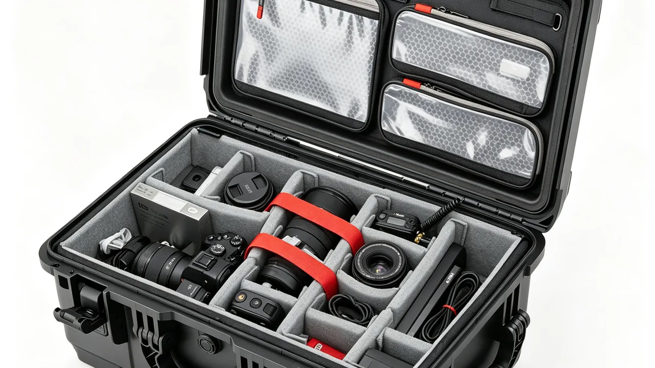
Diaphragm pumps move fluid by flexing an elastomeric or PTFE membrane back and forth, changing chamber volume instead of turning an impeller inside a sealed housing. Air-operated double-diaphragm units, motor-driven diaphragm pumps and metering diaphragm pumps are everywhere in acid and caustic transfer, electroplating bath circulation, paint and ink handling, lithium slurry dosing, and water treatment chemical feed. What actually sets the service interval of such a pump is rarely the casting or the motor. It is the diaphragm, the valve balls, the valve seats, the ball cages, the valve covers and the air distribution valves, a family of parts that mixes soft elastomers with hard ceramic and precision machined metal. JUNZHIJIA's position is that a case for these parts cannot follow the usual equipment-case logic of filling every void and clamping everything down. The design target has to shift from impact absorption alone to three simultaneous duties: prevent deformation, prevent contamination and prevent ageing. That means shape-retaining supports instead of compression for diaphragms, isolated individual pockets instead of mixed loading for balls and seats, and a clean sealed chamber instead of open-cell foam for air valves and pilot valves.
Transport losses on diaphragm pump spares are a cost most plants never isolate. On a typical air-operated double-diaphragm pump, diaphragms and valve balls account for well over half of the annual spare parts budget, yet a failure report that says "the new part failed right after installation" is usually blamed on supplier variation and almost never traced back to packaging. The real sequence is mundane: a rubber diaphragm gets squeezed sideways in the box and keeps a fold line that later becomes a stress riser and perforates after a few hundred thousand cycles; a PTFE diaphragm creeps under the weight of the parts stacked above it and shifts the stroke centre, which lowers volumetric efficiency and wears the ball out of round; balls and seats rattle against each other in a shared cavity and chip the ceramic or bruise the metal sealing cone; an air valve absorbs fibres and dust from ordinary foam and jams in its spool clearance. The common thread is that the damage is invisible at the moment the case is opened. This article walks through risk mapping, compartment design, cleanliness control, sealing and desiccation, and release inspection, so that spares can go straight onto the pump the day they arrive.
Table of Contents
- Transport damage patterns in diaphragm pump parts
- Material identity and residue risk before packaging
- Diaphragms: no compression, no folding
- Valve balls and seats: isolation and shape retention
- Ball cages, valve covers and flow path parts
- Air valves and pilot valves: ISO 4406 cleanliness control
- Seals, O-rings and wear parts: moisture and ageing
- Liner materials and compartment structure
- Case sealing, IP rating and pressure equalisation
- Transport test references, marking and traceability
- OEM and ODM customisation for pump model families
- Unpacking inspection and pre-installation check list
- Frequently Asked Questions
Transport damage patterns in diaphragm pump parts
The spare parts architecture of an air-operated double-diaphragm pump differs sharply from a centrifugal pump. There is no mechanical seal. A membrane separates the process fluid from the air side completely, and a main air valve or pilot valve handles the reversing logic. That architecture gives the pump real advantages with abrasive, viscous or shear-sensitive media, and it concentrates the weak points into a small number of components.
Field data collected across maintenance departments sorts arrival defects into four groups. The first is diaphragm creasing and perforation. The second is valve ball out-of-roundness together with bruising of the valve seat sealing face. The third is deformation of ball cages and valve covers. The fourth is sticking or internal leakage in air valves and pilot valves.
Each group has a different mechanism, and each needs a different structural answer. Diaphragm damage is deformation driven, so the governing variables are packing attitude and load path; the tighter the stack and the firmer the clamp, the worse the outcome. Ball and seat damage is collision driven, and the root cause is several hard parts sharing one cavity, taking turns being the hammer and the anvil as the vehicle vibrates. Cage and cover damage is static-load driven, produced by stacking weight resting on a thin-walled bayonet feature for weeks. Air valve damage is contamination driven, because dust, lint, moisture and oil all attack the running clearance of the spool.
Temperature adds a dimension that is easy to forget. Elastomers pass through their glass transition at low temperature, so hardness and brittleness rise together and an impact that would be harmless at room temperature can crack a diaphragm or an O-ring in a winter shipment. PTFE behaves in the opposite direction: creep accelerates markedly as temperature rises, so a diaphragm that is clamped down will keep deforming throughout a hot-weather journey. Thermal insulation and the climate of the shipping lane therefore belong in the design input, not in the afterthought column. General approaches to temperature boundaries are described in the material on extreme temperature case design, and its treatment of pressure differential across a sealed cavity applies directly to pneumatic parts.
Material identity and residue risk before packaging
The first question when designing a case for diaphragm pump parts is not about dimensions, it is about what the parts have been pumping. A brand-new spare and a repaired unit pulled from a chemical line need completely different protection. For a new part, the enemy is environmental corrosion and mechanical damage. For a used part, there is a third enemy: the residual process fluid, which will carry on reacting inside a closed box.
Residues of hydrochloric acid, sodium hypochlorite, sulphuric acid or sodium hydroxide keep evaporating inside a sealed case and build a low-concentration acidic or alkaline atmosphere. Solids in a slurry dry into a hard crust and then scrub the seat sealing face as the vehicle vibrates. Electroplating sludge and heavy metal residues accelerate pitting on stainless steel balls when the cavity is damp.
Material sensitivity varies widely, so material identity has to be established before anything is packed. Aluminium centre sections and aluminium pump bodies corrode uniformly above roughly pH 9 and pit in chloride environments, so used aluminium parts must be fully neutralised. A 316L stainless ball is most at risk from crevice corrosion; a trapped liquid film between ball and seat can pit the surface within days. Polypropylene and PVDF cages tolerate acids and bases well but swell or stress-crack in contact with oily residues and organic solvents. Rubber diaphragms have almost no resistance to ketones, esters and strong oxidisers, and residue contact produces swelling, softening and delamination.
A five-step cleaning routine is worth standardising. Rinse with process water to remove soluble material, neutralise with a weak acid or weak base until the effluent sits between pH 6.5 and 7.5, finish with deionised water, use a final rinse conductivity below 10 µS/cm as the working acceptance criterion, then blow every cavity dry with oil-free compressed air and confirm dryness. Incomplete drying is more dangerous than skipping the wash, because trapped water forms concentrated droplets as the vehicle vibrates and creates local pitting sites on sealing faces. Once cleaning has passed, apply the zoning logic described in protective case cleaning methods as a second confirmation before the parts move to the packing station. The table below summarises the control points by component.
| Component | Common materials | Main transport failure mode | Packaging control point |
|---|---|---|---|
| --- | --- | --- | --- |
| Diaphragm | PTFE, PTFE-faced composite, EPDM, FKM, neoprene | Creasing, cold flow, compression set | Curved support saddle, no stacking or banding, laid flat |
| Valve ball | PTFE, 316L stainless, alumina or zirconia ceramic, rubber-covered | Chipping, out-of-roundness, surface scratching | Individual hemispherical pocket, hard parts never touching |
| Valve seat | Stainless, PTFE, ceramic, seat with O-ring | Bruised sealing cone, cut O-ring | Sealing face up or isolated with inhibitor paper, never stacked on face |
| Ball cage and cover | Polypropylene, PVDF, stainless, aluminium | Bayonet ovalisation, wall collapse | Sleeve or pillar support, no loose foam chips as filler |
| Air valve and pilot valve | Aluminium body, stainless spool, engineering plastic pilot | Spool sticking, internal leakage, dust ingress | Clean sealed chamber, port plugs, antistatic liner |
| Fasteners and clamps | Stainless, zinc plated steel | Thread damage, coating wear then rust | Thread caps, separate compartments |
Diaphragms: no compression, no folding
The diaphragm is the component that most needs counter-intuitive handling. Standard packing practice puts soft parts at the bottom of the case as a cushion and stacks heavy parts on top, and for a diaphragm this is exactly the wrong arrangement. PTFE diaphragms creep under sustained load. Even at ordinary ambient temperature, a few kilograms of static load held for several weeks is enough to flatten the sealing lip and reduce the depth of the convolution, which shows up after installation as poor sealing and lower volumetric efficiency. Rubber diaphragms instead take a permanent compression set; the higher the compression, the higher the temperature and the longer the duration, the lower the recovery, and a flattened convolution will no longer seat against the valve plate. The first rule of diaphragm packing is therefore shape retention without load bearing.
In practice, use a support saddle or curved rest whose radius matches the diaphragm curvature, so the part sits in its free state with load distributed across the convolution that is designed to flex, rather than concentrated on the flat sealing edge. Never fold a diaphragm in half, never bundle diaphragms with cable ties or stretch film, and never vacuum pack them; negative pressure pulls the membrane to one side and produces the same plastic deformation as a static load. Two-piece diaphragms with inner and outer plates should be split for packing. The plates are rigid and can be secured together; the membrane must be laid flat, one piece per position, on a curved saddle with non-woven or PE interleaves between them. Plug the plate bolt holes with plastic caps so that dust cannot enter and cause thread damage during assembly.
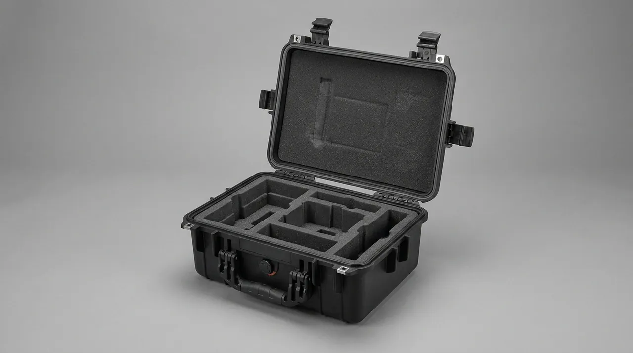
Composite diaphragms, which combine a PTFE face layer with a rubber backing, need one extra precaution. The PTFE face has high surface resistivity and readily attracts lint and dust by static, and any particle trapped on that face will be pressed into the valve plate during running and scratch it. The fabric reinforcement on the backing side snags easily, and a pulled fibre directly reduces tensile strength. Use antistatic EVA or conductive PE as the contact layer, and bag each diaphragm in a clean PE sleeve that is folded closed rather than evacuated. The illustration below shows a curved retention saddle machined to the diaphragm profile.
Stacking orientation must also be controlled after packing. A diaphragm case should be stored and shipped with the membrane horizontal, the saddle underneath and nothing heavy above, and the case should carry an orientation arrow plus a no-inversion marking. Where a carrier may invert the case, build the saddle to support both faces so that neither side of the diaphragm can receive the weight of other parts. For large diaphragms with an effective diameter above 300 mm, use one case per diaphragm or a drawer configuration so that the lower pieces in a stack are not under continuous load. Diaphragms held in stock for more than six months should be released to their free state and inspected for folds that do not recover before they are issued.
Valve balls and seats: isolation and shape retention
Valve balls and seats form the check valves of a diaphragm pump, and they are a matched kinematic pair whose whole function depends on close conformity. The roundness and surface finish of the ball, and the integrity and coaxiality of the seat cone, together determine suction lift and volumetric efficiency. Transport damage to this pair takes three forms: chipping from ball-to-ball impact, scratching from ball-to-metal contact, and bruising or ovalisation of the seat face under the weight of parts stacked above.
Ceramic balls are extremely sensitive to impact. Alumina and zirconia balls are hard and wear resistant, but their fracture toughness is a fraction of stainless steel, so two balls rolling freely in a case, or one ball striking the case wall over a bump, is enough to produce a micro chip. If that chip lands on the sealing band, the pump will leak internally on every stroke. Ceramic balls must therefore be located one per pocket, with the pocket-to-ball clearance held under 0.5 mm so the ball can barely roll, and the pocket surface must be softer than the ball to avoid reverse damage. Stainless balls tolerate more, but their surface finish requirements are just as tight, so they should not share a compartment with loose bolts or clamps. PTFE-covered and rubber-covered balls fail the opposite way: they deform plastically when a hard part presses into them, so they need a soft, clean contact surface.
Seats fail at the sealing face rather than in their outline, which changes the packing logic. Seat cones or flat faces should be oriented upward or isolated with corrosion inhibitor paper, and seats must never be stacked so that sealing faces touch each other. When metal and PTFE seats travel in the same case, the softer PTFE part must not contact a metal edge. For seats fitted with O-rings, check whether the cone can cut the ring, and bag the O-rings separately with a label tied to the part. Balls and seats should be identified as a set by pump position; note the pump model and the position number inside each compartment. Mixing balls and seats from different production runs can produce early leakage even when every individual dimension is in tolerance, because the contact angle of the cone varies slightly between runs.
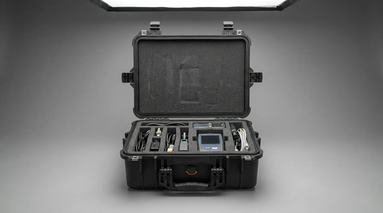
Arrival inspection should be quantified rather than visual. Measure ball diameter with a micrometer in three directions 60 degrees apart; the difference between the largest and smallest reading on the same ball is the out-of-roundness, and a value above the working threshold of 0.05 mm should be quarantined as a reject. Wipe the seat sealing face with a white cloth in a clean area and look for bright bruise marks or trapped fibres. The photograph below shows ceramic balls in individual pockets with seats compartmented alongside.
Ball cages, valve covers and flow path parts
Ball cages and valve covers are usually moulded in polypropylene or PVDF, or machined from stainless steel, and their job is to limit the axial travel of the ball while guiding it. What these parts have in common is thin walls, a bayonet or threaded interface and low section stiffness. The dominant transport risk is not impact at all, it is slow deformation under sustained static load. A seat, a clamp or a spare part from another pump resting on top of a cage will turn the bayonet from round to oval over a few weeks of stacking, and after installation the ball is guided off-axis, which produces eccentric wear and noise.
Cages and covers therefore need axial support rather than circumferential squeeze. A workable design uses a pillar or sleeve locator: the cage rests on its flange or threaded face against a rigid support ring, so that axial load goes into the ring and the cylindrical wall carries no radial load at all. Never fill the space around a cage with loose foam chips, shredded paper or bubble wrap. Such fillers compact and shift under vibration, ending up applying lateral pressure to the cage, and the debris itself becomes a contamination source. Aluminium flow path parts and valve bodies also need thread protection, so blank the inlet and outlet ports with thread caps or soft plugs.
Flanges and clamp grooves are mating surfaces and must not touch hard parts. Place HDPE or rigid card separators between flange faces, sized to cover the whole sealing surface and to overhang it by at least 5 mm so that a corner cannot dig in. When a stainless cage shares a case with an aluminium flow part, avoid prolonged direct contact; in a damp environment the pair forms a galvanic couple, the aluminium becomes the anode and develops white powdery corrosion product. Separate compartments, or an insulating film at the contact face, removes the risk entirely.
Air valves and pilot valves: ISO 4406 cleanliness control
The air valve is the pacemaker of an air-operated double-diaphragm pump. The main valve, the pilot valve and the air distribution valve all rely on a spool sliding back and forth inside a sleeve to reverse the pump. The running clearance in these parts is measured in micrometres, often only a few micrometres to somewhere in the low teens, and reliable operation depends on no solid particle of a size comparable to that clearance ever entering the gap. Once dust, metal swarf or fibre gets in, the mild outcome is delayed shifting and an unstable cycle rate, and the severe outcome is a spool that jams completely or wears eccentrically and leaks internally for good.
This is why ordinary open-cell foam or felt must never be used to pack air valves. Both materials shed continuously under transport vibration. Use closed-cell, low-outgassing, clean liner material instead, and complete the sealing operation in an environment classified under ISO 14644. Cleanliness targets can be expressed using the particle counting code of ISO 4406, in which three numbers give the population of particles larger than 4 µm, larger than 6 µm and larger than 14 µm per millilitre. Pneumatic parts use gas rather than liquid, but the same code structure gives a clear and comparable way to describe an assembly and packing environment. The table below pairs typical codes with applications as an engineering rule of thumb.
| ISO 4406 code | Particle control level | Typical application |
|---|---|---|
| --- | --- | --- |
| 20/18/15 | General industrial cleanliness | External brackets, clamps, structural parts |
| 18/16/13 | Normal hydraulic and pneumatic systems | Cylinders, general pneumatic actuators |
| 16/14/11 | Precision pneumatics and proportional valves | Pilot valves, standard air valve assemblies |
| 14/12/9 | High cleanliness pneumatic servo | Miniature spools, very tight distribution clearances |
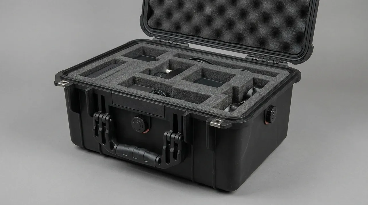
In practice, bag each air valve individually in a clean PE or foil laminate pouch, folding the neck closed rather than evacuating it. Then place the pouch in a dedicated clean compartment inside the case, with closed-cell walls treated for static dissipation. Blank every air port, pilot port and silencer port with a dedicated plug, and leave those plugs in place until the moment of assembly in a controlled area. Filter elements inside dryers and silencers are consumables and should be packed separately with their cleanliness status marked. The image below shows an air valve in its individual clean pouch with port plugs fitted.
One caveat is that clean packing only performs as well as the case sealing around it. If the case itself provides only ordinary dust protection, the clean inner bag will still be penetrated gradually by moisture and particles on a long sea voyage, so the air valve compartment should reach the IP6X dust-tight level defined in IEC 60529 together with the case body, and a desiccant pack should be added inside. Clean packaging also needs a shelf life after opening; a working rule is to complete assembly within 24 hours of opening the pouch in a controlled area.
Seals, O-rings and wear parts: moisture and ageing
Seals and O-rings are small, cheap and very often the first items in a spare parts case to become unusable. Rubber failure mechanisms are mainly compression set, ozone cracking and media swelling. The killers during transport and storage are ozone, ultraviolet light, heat and oil contamination. Ozone comes from motor commutation, welding fumes and urban air, and it attacks stretched rubber by growing cracks perpendicular to the stress direction. Ultraviolet light from warehouse lamps and daylight breaks polymer chains and leaves a powdery, chalky surface. Heat accelerates every ageing reaction, and as a rule of thumb the rate roughly doubles for every 10 degrees Celsius of additional temperature.
Rubber seals should therefore be packed to keep light out, keep ozone out, keep oil out and control temperature and humidity. Dark or opaque foil laminate pouches are the right choice, and the liner must not be plasticised soft PVC film, which can migrate plasticiser into the rubber. Store at 15 to 25 degrees Celsius and below 65 percent relative humidity, well away from motors, welding sets and other ozone sources. Shelf life can be managed against working values: roughly 5 years for nitrile, 8 years for EPDM and 10 years for fluoroelastomer, after which parts should be sampled and preferably reserved for non-critical positions. The general principles of ISO 2230 on rubber storage give a useful framework for a stock ledger.
PTFE-encapsulated O-rings and solid PTFE seals need different treatment. PTFE itself resists ageing and does not absorb moisture, but it scratches easily and creeps under compression, so it must be kept away from hard parts and away from long-term load. Polyurethane seals are the opposite case: they hydrolyse in humid conditions and gradually soften and lose strength, so they require thorough drying. Fit the whole wear parts case with silica gel desiccant at a rate of 50 to 80 grams per cubic metre of cavity volume, bag the desiccant separately and label both the loading date and the recommended replacement date. For voyages longer than 60 days, check the indicator card or desiccant colour immediately after the case is opened at destination. The sealing and moisture strategy for the case as a whole should follow the logic set out in case seal material selection, matching seal compound and compression to the actual climate and voyage length.
Liner materials and compartment structure
The liner of a diaphragm pump parts case has to balance cushioning, compression resistance, cleanliness, static dissipation and moisture control. Each material has a clear boundary of usefulness, and choosing the wrong liner can be worse than using none at all. The comparison below is intended for selecting material by component type.
| Liner material | Cushioning | Compression resistance | Outgassing | Antistatic | Typical components |
|---|---|---|---|---|---|
| --- | --- | --- | --- | --- | --- |
| Standard EVA foam | Good | Medium | Medium | No | Castings, brackets, structural parts |
| Antistatic EVA | Good | Medium | Low | Yes | Diaphragms, PTFE parts, clean compartments |
| Cross-linked PE | Fair | High | Low | No | Seats, cages, flange parts |
| Expanded polypropylene | Excellent | Medium to high | Low | No | Large diaphragms, valve bodies |
| Closed-cell PE board | Low | Very high | Very low | Can be treated | Clean compartment walls, load-bearing base |
| Polyurethane foam | Excellent | Medium | Medium to high | Can be treated | General cushioning, not clean chambers |
Compartment structure follows from part count and from the risk of mixing. For a small number of high-value spares, the usual answer is a main case plus dedicated inner boxes: the main case carries transport and stacking loads while the inner boxes deliver cleanliness and shape retention, with air valves and balls in separate inner boxes and diaphragms held on curved saddles. Where many variants ship together, use a removable divider system and allocate zones by pump model or pump position. The dividers themselves must have rigid support rather than relying on foam adhesive, otherwise they shift during a ship's roll and the compartments merge. Lead times and tooling cost for moulded liners are discussed in the custom foam insert guide, and modular divider configurations are covered in the material on case removable divider systems.
Case sealing, IP rating and pressure equalisation
The right sealing level for a diaphragm pump spare parts case depends on what each component is sensitive to. Diaphragms care about ozone, ultraviolet light and deformation, and have only moderate demands for water exclusion. Balls and seats care about moisture driven pitting and rust, and need a stable low-humidity environment. Air valves and pilot valves care about both particles and water vapour, and have the strictest requirement of all. Dust protection is expressed under IEC 60529, or the equivalent GB/T 4208: IP5X permits limited dust entry without functional effect, while IP6X is dust tight. Water protection rises from IPX4 for splashing to IPX7 for short-term immersion. The clean compartment should reach at least IP6X, with the case body at IP65 or IP66.
For the seal itself, use a silicone or EPDM gasket around the lid with a compression of 25 to 35 percent of section height. Too little compression leaks, and too much takes a permanent set so that the gasket loses its rebound after repeated opening. Long sea voyages justify a double seal, with an outer water barrier and an inner dust barrier. Latches and hinges are the most common points of sealing failure, and the selection points are set out in the material on toolbox hinge latch and seal design: the latch needs anti-loosening and adjustable preload, the hinge pin needs corrosion protection, and neither may become brittle at low temperature. Returnable cases with a high opening count should have latch preload and gasket rebound checked on a fixed schedule.
Pressure equalisation is routinely overlooked. A sealed case passes through day and night temperature swings and changes in altitude, and the differential across the wall can reach several thousand pascals. When internal air contracts on cooling, outside moisture is drawn in; when it expands, air carrying water vapour does not readily leave. For a clean compartment, this breathing cycle shortens the retention time of the clean state significantly. The answer is a pressure equalisation valve that vents without compromising the dust and water rating, and the principle and selection logic are covered in the material on case pressure equalisation valves. Where the air valve components are extremely moisture sensitive and the journey is short, a fully sealed case plus desiccant is a valid alternative, using the desiccant to absorb the small amount of water vapour admitted by breathing. Aluminium centre sections that are sensitive to alkaline residue can also follow the residue labelling and segregation practice described in hazmat transport case compliance, so they are not shipped with other parts that carry chemical residue.
Transport test references, marking and traceability
An engineering case for diaphragm pump spares should be validated by transport testing rather than by judgement alone. Useful references include the ISTA series of packaged product performance tests for less-than-truckload and parcel distribution, ASTM D4169 distribution cycle testing for combined vibration, drop, stacking and low pressure, and the GB/T 4857 series for basic vibration, impact, stacking and drop methods. Low pressure matters especially for cases that may travel by air, because a sealed case without pressure equalisation sees its greatest differential in that part of the cycle. Where a customer asks for MIL-STD-810H methods as the environmental test basis, its vibration and shock methods can be used, but the report should state clearly that this is a reference to test methods and does not constitute any military certification.
Marking should follow GB/T 191 and GB/T 13384: this way up, keep dry, stacking limit or do not stack, centre of gravity and lifting points must be legible and must not fall off in transit. Multi-case spare kits need item numbers and a total count so that nothing is lost when shipments are split. Clean compartments should carry a note advising that the environment be confirmed before the pack is opened.
A traceability record is part of the protection, not an administrative extra. Record on both the case and inside each compartment: pump model and position, part name and material, material batch number, packing date, cleanliness level, desiccant loading and replacement dates, and the names of the packer and the checker. Repaired parts need an additional record of the cleaning method and the post-cleaning test result. On request, JUNZHIJIA can supply a material-to-model matching list, a signed liner drawing record and a packing inspection record, so that a parts consignment arrives with a complete chain that a quality department can use to resolve any dispute quickly.
OEM and ODM customisation for pump model families
The diaphragm pump model range is broad. It runs from miniature metering pumps with quarter-inch ports to large double-diaphragm units above three inches, and diaphragm diameter, ball size, cage design and air valve type differ substantially across that range. A universal case with universal foam is therefore almost always an inefficient solution in real use. Customisation pays off in three places: a liner moulded to the actual component geometry rather than a generic pad that is either too tight or too loose; compartments divided by pump position and component class so clean parts never travel with castings; and labelling by pump model and position so that no re-sorting is needed at the point of issue.
The process normally starts with drawings and physical parts. Where a 3D model or drawing exists, the free diaphragm diameter, ball diameter, seat outside diameter and flange dimensions drive the saddle and pocket design directly. Where only the part is available, a 3D scan or careful manual measurement supplies the critical dimensions. For a first article, validate a single liner before committing to the full case: confirm how the diaphragm seats on the saddle, check pocket clearance and check how the part lifts out. JUNZHIJIA provides liner design, sample fitting and volume supply as a package, supports OEM and ODM programmes and can match sealing parts to specific pump models. This product series is manufactured by Kexin New Materials (Guangdong) Co., Ltd. For export projects, sealing level and desiccant configuration can be adjusted to the destination climate and transport mode, with the necessary test and packing records supplied alongside.
Unpacking inspection and pre-installation check list
Whether the packing job succeeded is ultimately decided by the facts at the moment the case is opened. Turn the acceptance steps into a check list and tick each item before the parts go to the assembly station, so that there is no accountability gap between receiving and installation.
- Case and latches: no dents, water staining or rupture, latches fully engaged, gasket free of tears or obvious flattening.
- Desiccant status: indicator card or silica gel colour normal, or weight compared against the loading record, with replacement required above 20 percent moisture gain from the initial value.
- Clean compartment: inner pouch intact, all port plugs present, compartment walls free of dust and debris.
- Diaphragms: laid flat in their free state, with no non-recovering fold, flattened convolution or curled edge.
- Valve balls: each ball visually checked for chipping and scratching, roundness sampled, no mismatched seat in the same compartment.
- Valve seats: sealing faces visible, no bright bruise marks, no trapped fibre, O-rings free of cuts.
- Cages and covers: bayonet features visibly round, no abnormal elastic deformation under light hand pressure.
- Air valves and pilot valves: shifting action tested by hand or with a low-pressure air supply, movement smooth without sticking, port threads undamaged.
- Fasteners: threads free of impact damage, plating intact, quantity matching the packing list.
- Documents: packing list, material matching list and cleaning records present, batch numbers traceable.
Any item that fails should be quarantined along with the rest of its production batch rather than patched on the spot. Once a rubber or PTFE part has taken a non-recovering set or absorbed contamination, there is no reliable way to restore its original performance in a receiving area, and replacement is the only correct action.
Frequently Asked Questions
Q: Why can a PTFE diaphragm not be clamped down the way an ordinary rubber part can?
A: PTFE is a classic viscoelastic material and creeps under sustained load, which means it slowly takes a permanent plastic set at temperatures far below its melting point. Once a diaphragm is clamped, the loaded area thins progressively, the sealing lip changes from line contact to face contact, and the convolution geometry drifts away from its design value. After installation the symptoms are poor sealing, reduced volumetric efficiency and a shifted stroke centre, and the poor conformity also accelerates eccentric wear on the valve ball. Creep rate rises with temperature, so a long hot-weather journey makes the problem noticeably worse. The correct approach is to let the diaphragm rest in its free state on a curved saddle that matches its profile, so the load lands on the convolution that is designed to flex rather than on the sealing edge, and position is maintained by shape retention rather than by clamping. If travel must be limited, use a soft stop block, never a cable tie, stretch film or vacuum bag.
Q: Can valve balls and valve seats be stored in the same liner cavity?
A: It is not advisable, particularly with ceramic balls and metal seats. Both parts have sealing performance governed directly by surface quality, and when they share a cavity the transport vibration makes each one an impact source for the other. Ceramic balls are extremely hard but have low toughness, so two balls striking each other can produce a micro chip right on the sealing band; a metal seat edge striking a ball scratches the surface and work-hardens it locally. Shared storage also creates pairing risk, because the cone contact angle can differ slightly between production batches, and a mismatched pair will leak from the start even though every individual dimension is within tolerance. The recommended arrangement gives each ball its own hemispherical pocket with clearance under 0.5 mm and a pocket surface softer than the ball, while seats are compartmented with the sealing face upward, or stacked with rigid card between them, and seats with O-rings have the ring bagged separately. Labelling by pump position saves sorting time at assembly.
Q: Do air valves and pilot valves really need cleanliness-controlled packing?
A: Yes, and in most cases they carry the strictest requirement in the whole case. The spool-to-sleeve clearance in an air valve is often only a few micrometres to somewhere in the low teens, so any particle approaching that size in the gap can cause delayed shifting, an unstable cycle rate, or in the worst case a full jam, and spool wear can create a permanent internal leak. The common field mistake is to pack air valves with castings in ordinary open-cell foam. The foam sheds continuously under vibration while sand and metal powder from the castings migrate around the cavity, and both end up settling on the spool surfaces. Set the cleanliness target with the ISO 4406 particle counting scheme, using 16/14/11 as a working target for precision air valves, complete the packing in an ISO 14644 controlled environment, use closed-cell low-outgassing antistatic liner material, plug every air and pilot port, and keep the valve physically separated from castings in its own compartment.
Q: What should be done if condensation appears inside the case in transit?
A: Condensation happens when water vapour in the trapped air reaches its dew point as the temperature falls. Handle it in two stages: first remove the sources of water vapour that get in, then make sure the small amount that does get in is absorbed rather than deposited on component surfaces. Practically, dry the parts and the liner thoroughly before packing, avoid packing during rain or in a high-humidity window, load silica gel at 50 to 80 grams per cubic metre of cavity volume and record the loading date, hold gasket compression at 25 to 35 percent, and use a double seal for long sea voyages. Where a case is fully sealed and the journey involves large temperature swings, fit a pressure equalisation valve so that internal and external pressure track each other and the case does not draw outside air in as it cools. A case that has already condensed should not simply be opened and put into storage; move it to a dry area, open it there, replace the desiccant and apply corrosion protection to the metal parts.
Q: How clean does a part that has pumped acid or caustic have to be before packing?
A: The acceptance standard is no residual electrolyte, no residual solids and a neutral surface. Standardise a five-step routine: rinse with water to remove soluble material and loose solids, neutralise with a weak acid or base and verify that the effluent pH is between 6.5 and 7.5, finish with deionised water using a final rinse conductivity below 10 µS/cm as the working criterion, then blow dry with oil-free compressed air and confirm with a humidity indicator or moisture meter. Parts that have handled slurry need a dedicated check of crevices and threaded holes, because solids collect there, dry into a hard crust and then scratch sealing faces as the vehicle vibrates. Aluminium parts need particular attention to alkaline residue, and stainless parts to crevice corrosion from chloride residue. Move the part to the packing station immediately after cleaning passes, so that it cannot be recontaminated. Record the neutralisation pH and the final rinse conductivity for every batch, and keep that record with the case, because a disputed arrival claim is far easier to settle when the cleaning data already exists on paper.
Q: Can rubber and PTFE diaphragms share a single protective case?
A: They can share a case but not a chamber, and the two materials want opposite environments. Rubber diaphragms need protection from ozone, ultraviolet light, oil and heat, which means light exclusion, oil exclusion and temperature control, and the packaging must not carry plasticiser migration risk. PTFE diaphragms resist ageing and do not absorb moisture, but they scratch, attract dust by static and creep under sustained load, so they need antistatic liner material and free-state shape retention. If both sit in one chamber, only one side can be satisfied: a light-tight enclosure chosen for the rubber parts increases static build-up on the PTFE parts, while antistatic foam chosen for the PTFE parts may release volatiles that are unfriendly to the rubber. The workable answer is two physically separated chambers inside the main case, each with its own liner and desiccant, and separate opening and storage instructions marked on the outside. Where volumes are small and only one chamber is practical, prioritise the PTFE parts with an antistatic liner and keep the rubber parts inside a sealed opaque pouch within that same chamber, accepting that the rubber items must then be issued and consumed first.
Q: The spares have been in the warehouse for over a year. Can the case still be used?
A: The case body is normally still serviceable, but the protective state inside must be re-assessed. Three checks matter most: whether the gasket still has rebound or shows permanent flattening and cracking, whether the desiccant is saturated, judged by indicator colour, silica gel colour or weight gain above 20 percent of the initial value, and whether rubber and PTFE parts have taken a permanent set under long-term load, especially any diaphragm that has been held clamped. Rubber seals stored beyond a year should be assessed against material shelf life values, roughly 5 years for nitrile, 8 years for EPDM and 10 years for fluoroelastomer, and parts at or past those points should be sampled before use is approved. Open and inspect each case every six months and keep a record, and avoid storing cases directly on the floor, against an outside wall or in direct sunlight. Parts that have already been issued once and returned unused should be re-inspected before they go back into stock, because a part that has travelled and come back has been exposed even if it was never fitted.
Q: What testing and documentation is needed for diaphragm pump spares shipped overseas by sea?
A: On the documentation side, prepare at least a packing list, a material and pump model matching list, a packing inspection record and, for repaired parts, a cleaning record, and make sure the case marking meets the graphical and text requirements of GB/T 191 and GB/T 13384. On the testing side, choose references by transport mode: the ISTA packaged product performance series for less-than-truckload and parcel movement, ASTM D4169 for a combined distribution cycle, and the GB/T 4857 series for domestic transport and basic mechanical methods. Air freight needs particular attention to the low-pressure stage, and sealed cases should have a pressure equalisation valve or an equivalent venting feature. Where a customer asks for corrosion verification, the neutral salt spray method of GB/T 10125 can be used for sampling on metal parts. If MIL-STD-810H methods are specified as the environmental test basis, the report should state that they are referenced as test methods and do not represent any military certification.
Conclusion and Related Reading
Protecting diaphragm pump spares is a contest with material behaviour: PTFE creeps, rubber takes a set, ceramic chips, spools hate particles, aluminium dislikes alkali. Encode those behaviours into liner geometry, compartment logic, cleanliness class and sealing. JUNZHIJIA recommends three separate zones in every case, and a controlled microclimate around them.
Related Reading