

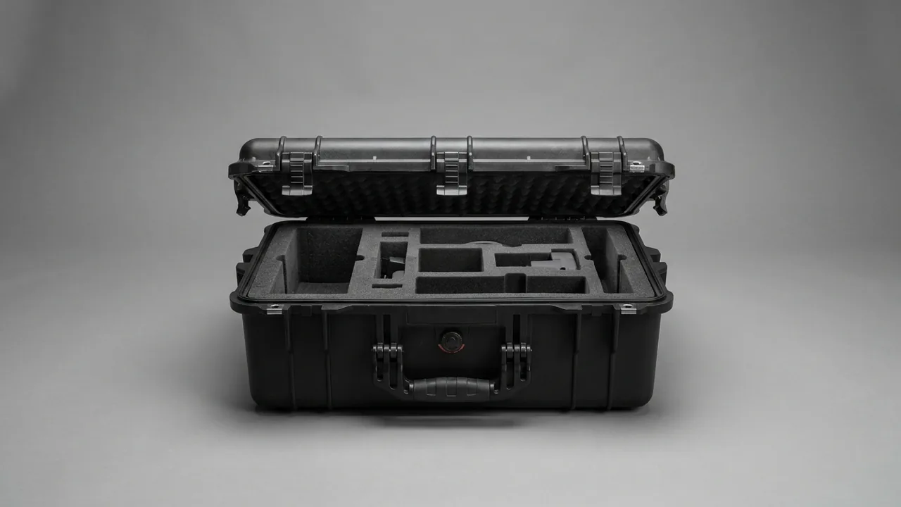
Protecting a high-speed centrifuge rotor during transport is fundamentally about preserving a mass distribution and a set of fit tolerances that were established on a balancing machine. Every rotor leaves the factory dynamically balanced. Any impact that a technician cannot see with the naked eye, a scratch inside a tube bore, an indentation on a taper seat, will be amplified by centrifugal force once the rotor spins at tens of thousands of rpm and will show up as vibration, noise, or premature bearing failure. The first specification for a rotor case is therefore restraint, not shock resistance: the rotor must move essentially zero relative to the case. On top of that, rotors, seals, buckets and adapters are made of different materials with different failure modes, so they must be stored in separate compartments and restrained individually.
This guide is written for laboratory asset managers, procurement teams and third-party logistics providers. It breaks the rotor case down into six verifiable dimensions: balance protection, thermal and vibration control, cleanliness and biosafety, insert structure, material selection, and packaging validation. Parameters, standards and acceptance checklists are given so they can be used directly in a quotation or a prototype request.
Most rotor damage does not happen during a run. It happens during the short move from one bench to another. The usual laboratory practice is to put the rotor back into the original shipping carton, stuff in a few air pillows, or drop it into a generic tote. That kind of packing stops a visible knock, but it does nothing about the sustained high-frequency vibration and repeated small displacement of a hand truck ride. The operator only discovers the problem when the rotor is reinstalled and spun up: abnormal noise, a vibration reading that no longer matches the historical baseline. By then the rotor generally needs to go back to the manufacturer, and most manufacturers will not certify a rotor that shows signs of impact. Rotors range from a few thousand to several hundred thousand in unit cost, and the downtime while waiting is worse. This article addresses that underestimated last mile.
Contents
- 1. Why a high-speed rotor demands an extreme level of transport protection
- 2. Component categories and the specific weak point of each
- 3. Balance protection: working backward from permissible residual unbalance
- 4. Temperature and vibration: moving the natural frequency out of the excitation band
- 5. Cleanliness and contamination control in a biosafety context
- 6. Insert structure: form-fit restraint and swappable modules
- 7. Compartmentalizing seals, buckets and adapters
- 8. Shell material selection: IP rating versus chemical resistance
- 9. Stress corrosion and the specific risk to aluminum rotors
- 10. Structural strength, latches and pressure equalization
- 11. Packaging validation: ISTA, GB/T 4857 and ASTM D4169
- 12. Operating and maintenance discipline: cleaning, drying and re-inspection
- 13. Customization workflow and OEM/ODM collaboration
- 14. Purchasing acceptance checklist and common misconceptions
- Frequently Asked Questions
- Conclusion and Further Reading
1. Why a high-speed rotor demands an extreme level of transport protection
Benchtop high-speed centrifuges commonly run between 12,000 and 30,000 rpm, while ultracentrifuges reach 80,000 to 150,000 rpm. At 20,000 rpm with a 200 mm rotor diameter, the peripheral speed at the rim is roughly 209 meters per second, about two thirds the speed of sound. Centrifugal stress in the rotor body at that point reaches the hundreds of megapascals. The design margin is generous, but that margin assumes the mass distribution still matches the value established at the factory.
Balance quality is normally specified as G2.5 or G6.3 under ISO 1940-1. The permissible residual unbalance can be estimated as:
U = 9549 x G x m / n
Here U is the permissible residual unbalance in gram-millimeters, G is the balance quality grade in millimeters per second, m is rotor mass in kilograms, and n is operating speed in rpm. For a 6 kg rotor at G6.3 and 20,000 rpm, U works out to approximately 18 gram-millimeters. At a radius of 100 mm that is equivalent to a mass offset of about 0.18 grams. In practical terms, a metal chip the size of a grain of rice that falls off the rim, or a 0.05 mm plastic indentation on the wall of a tube bore, consumes the entire balance allowance.
Transport introduces four categories of damage. First, local plastic deformation from impact: when drop acceleration reaches 50 to 100 g, tube bore edges and the outer rim are the first areas to yield. Second, scoring of mating surfaces: the rotor taper and the spindle taper are a high-precision fit, and any hard particle or relative sliding will gall the surfaces and degrade mounting concentricity. Third, damage to threads and locking hardware: rotor lock nuts and quick-lock lid catches are thin-walled load-bearing parts that deform easily under side impact. Fourth, crushing of seal grooves: once an O-ring groove develops an indentation or a burr, both airtight and biological sealing are lost.
The first three categories are silent failures. The rotor looks intact and feels normal, and the problem only appears at speed. The design objective of a rotor case is therefore not to look rugged. It is to keep in-case acceleration and relative displacement within defined limits.
2. Component categories and the specific weak point of each
A single case often has to hold the rotor body plus its accessories, and the failure mechanisms differ substantially between them. Classification comes first; compartmentalization follows.
| Component | Typical material | Main weak point | Protection priority |
|---|---|---|---|
| --- | --- | --- | --- |
| Angle rotor | 7075-T6 aluminum, titanium | Tube bore walls, taper seat, rim | Form-fit restraint, no hard-point support |
| Swing-out rotor body | Aluminum, stainless steel | Trunnion pins and pin bores | Stored separately, no contact with buckets |
| Bucket / centrifuge cup | Aluminum, stainless steel, carbon fiber | Rim flare, base weld | Dedicated cavity, upright orientation |
| Ultracentrifuge rotor | Titanium, carbon fiber winding | Fiber layers, seal grooves | Impact and moisture protection, no squeezing |
| Tube adapter | PP, PC, aluminum | Cup mouth, taper fit | Kit-indexed storage, never stacked |
| O-ring seals | FKM fluoroelastomer, silicone, EPDM | Compression set, aging, ozone cracking | Constant temperature, dark, uncompressed, separate cells |
| Rotor lid / quick-lock lid | Aluminum, PC, PPS | Catch tabs, sealing face | Dedicated cavity, sealing face up |
Two details in that table are frequently overlooked. First, the trunnion pin fit between a bucket and a swing-out rotor is a wear-sensitive joint. If the bucket is left hanging on the rotor during transport, fretting between pin and bore accumulates irreversibly and changes the swing-out angle and balance state. Buckets must be removed and restrained separately. Second, elastomeric seals take a permanent set when compressed for long periods. They must not be weighted down and must not touch hard rotor surfaces. Give them their own small cells where they sit freely.
3. Balance protection: working backward from permissible residual unbalance
Translating balance allowance into displacement and acceleration targets gives the design a measurable goal. Take the 6 kg angle rotor again, with roughly 18 gram-millimeters of permissible residual unbalance. If the rotor slides 2 mm against its insert during transport, and only 0.2 kg of local mass is involved, the equivalent unbalance reaches 400 gram-millimeters, more than twenty times the allowance. That arithmetic is the basis for the rule that restraint outranks cushioning. Cushioning absorbs energy; restraint prevents the creation of new unbalance. The two are not interchangeable.
Four concrete rules follow from that objective:
- The rotor must contact only flexible insert material, never the hard case wall or a metal accessory.
- Hard-point support is prohibited. Any point contact formed by a metal bolt or a rigid plastic post concentrates impact into a very small area.
- Never stack rotors. When two rotors sit one above the other, the lower rim carries the full mass of the upper rotor, and a shock event will almost certainly cause local yielding.
- Never strap or tape the rotor across a tube bore or the taper. The adhesive residue left after removal and the local preload are both hazards.
Inserts are normally built as a two-layer system. The restraint layer that touches the rotor is 30 to 50 Shore A EVA or cross-linked PE foam, which balances forming accuracy with resilience. The outer cushioning layer is PE foam at 25 to 45 kg per cubic meter, which dissipates impact energy. The restraint cavities should be lofted from the actual rotor outline, with a clearance of 0.5 to 1.5 mm. Too loose and the cavity does nothing; too tight and the rotor gets scratched every time it goes in or out.
4. Temperature and vibration: moving the natural frequency out of the excitation band
Temperature affects a rotor in two ways. The first is dimensional drift. Aluminum has a coefficient of thermal expansion near 23 x 10-6 per kelvin, titanium about 8.6 x 10⁻⁶, and carbon fiber composites near zero or slightly negative along the fiber axis. A 200 mm aluminum rotor changes diameter by roughly 0.35 mm across a -20 C to +55 C span. The second is material behavior: some elastomeric seals harden and lose elasticity at low temperature, while heat accelerates aging. Hold transport temperature between -20 C and +55 C, and narrow that to -10 C to +40 C for ultracentrifuge and carbon fiber rotors. A temperature recording label inside the case provides traceability.
The core of vibration design is avoiding resonant amplification. A packaging system is fundamentally a mass-spring system whose natural frequency depends on insert stiffness and payload mass. Road transport concentrates excitation energy between 5 and 200 Hz, with the strongest contributions from road input at 10 to 30 Hz and from body and engine at 50 to 100 Hz. The design goal is to push the system natural frequency below 8 Hz or above 60 Hz so that primary excitation falls outside the amplification zone. In practice it is easier to raise damping: add a high-damping layer between the EVA restraint layer and the PE cushioning layer, or select a cross-linked PE with higher hysteresis.
Relevant test methods may be referenced from MIL-STD-810H Method 501 for high temperature, Method 502 for low temperature, Method 514 for vibration and Method 516 for shock. These references are used only as environmental test methodology; they do not represent any military certification.
| Test item | Reference standard | Suggested level (example) | What to watch |
|---|---|---|---|
| --- | --- | --- | --- |
| Random vibration | MIL-STD-810H Method 514 / ASTM D4169 | 1.04 g rms, 1 h per axis | Fastener loosening, insert collapse |
| Mechanical shock | MIL-STD-810H Method 516 | Half-sine 25 to 40 g, 6 to 11 ms | Local yielding at rotor rim |
| Drop | ISTA 3A / GB/T 4857.5 | Mass-based schedule, 6 to 9 drops | Corners and latch area |
| Low-temperature storage | MIL-STD-810H Method 502 | -20 C, 24 h | Elastomer hardening, seal failure |
| High-temperature storage | MIL-STD-810H Method 501 | +55 C, 24 h | Foam compression set, adhesive softening |
5. Cleanliness and contamination control in a biosafety context
Centrifuges are used heavily in biological sample processing, so rotor surfaces may carry aerosols, culture media, blood fractions or nucleic acid fragments. If the transport packaging uses open-cell foam, cardboard or wooden blocks, those materials shed particles and adsorb residues, contaminating both the rotor and the next environment it enters. For higher cleanliness requirements, treat the interior volume as a controlled area, following the classification logic of ISO 14644-1.
Practical measures include:
- Use closed-cell foam throughout so the insert does not absorb liquid or shed debris, and so its surface can be wiped with 70 percent ethanol, isopropanol or a quaternary ammonium disinfectant.
- Design the insert as a module that lifts out as a single piece so it can be cleaned, disinfected and dried separately before being put back.
- Do not place cardboard, wooden blocks or corrugated pads inside the case. Fibrous materials are both a particle source and a moisture source.
- Store seals in separate cells away from the rotor to avoid cross-contamination.
- Where infectious substances are involved, packaging should follow the applicable requirements of UN 3373 and Packing Instruction P650. This article covers structural guidance only; the compliance determination must be made by the institution's biosafety officer.
Where static control is needed, the case and insert can be made from modified materials with a surface resistivity in the 10^6 to 10^9 ohm range to limit particle attraction. See ESD shielded case design for structural details.
6. Insert structure: form-fit restraint and swappable modules
The insert is the only part of a rotor case that directly determines whether protection succeeds. Structurally it should have three layers. The outermost is the case shell, which carries stacking and lifting loads. The middle is the cushioning layer, responsible for energy absorption. The innermost is the restraint layer, which locks the rotor into its designed position.
There are three ways to build the restraint layer, each suited to a different situation:
- Fully form-fit cavity. Molded once around the rotor outline and tube bore pattern, this gives the highest locating accuracy and suits a dedicated case for a single rotor model. The drawback is that it becomes useless if the model changes, so it fits laboratories with a large installed base.
- Central locating post with annular supports. This uses the rotor's central bore as the datum with flexible supports around the perimeter. It is the easiest to load and unload and suits applications with frequent transfers.
- Swappable module system. The base plate is a standard grid and the restraint modules are changed by model. One case can cover three to five rotor types, which suits mixed-model laboratories and third-party calibration bodies.
Whichever approach is chosen, mark the model, serial number and insertion orientation on the surface of the restraint layer so the rotor cannot be placed the wrong way or in the wrong cavity. For swing-out rotors with buckets, dedicate a separate bucket bay in the same case and isolate the rotor body from the buckets with a divider.
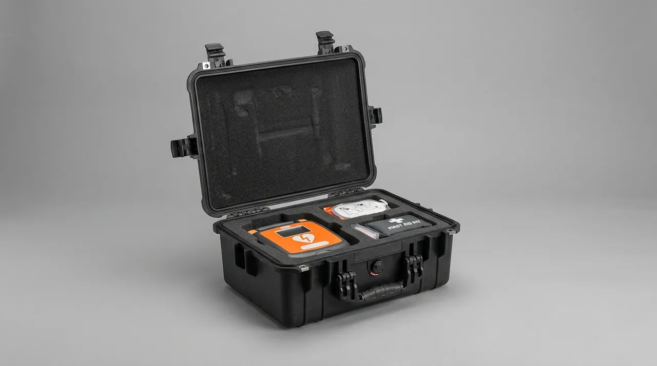
Insert fabrication must match the accuracy requirement. Hand cutting is fine for one-off prototypes but has poor consistency. CNC routing or thermoforming suits volume production and can hold cavity repeatability within plus or minus 0.3 mm, which makes it the better choice for a long-service fixed package. For a fuller comparison of insert approaches, see custom foam insert design guide and EVA foam insert custom process.
For a buyer with a single machine and a single model, tooling amortization often does not pay off. A universal base plate with a few local custom modules is usually the better route, and the costing method in custom case mold cost analysis can be used to compare the two.
7. Compartmentalizing seals, buckets and adapters
These three component families are small, numerous and easily lost, and their failure modes differ, so they must be managed by compartment.
- Seal compartment. Fluoroelastomer O-rings take a permanent set if stored under compression. Put them in individual cells by size, leave them uncompressed, keep them dark, and keep them away from ozone sources such as electric motors. Keep silicone parts away from sulfur-cured rubber to prevent migration.
- Bucket compartment. The mouth of a PP or PC bucket is a precision-sensitive feature, so stacking is prohibited. Use numbered form-fit slots, one slot per part number, so the count can be verified quickly when loading back.
- Adapter compartment. Adapters are used as sets, and a single case may hold 1.5 mL, 15 mL and 50 mL sizes at once. Label each slot with the size and the matching bore number to prevent mismatching, which causes imbalance during a run.
- Lid compartment. Quick-lock lid catch tabs are thin-walled. Give them a dedicated cavity, keep the sealing face up, and keep them away from metal parts.
Compartmentalization has a second benefit that is easy to overlook: counting speed. Rotor assembly before a run is usually time-pressured. When the storage layout matches the assembly sequence and the slot numbering, verification time drops by more than half and the chance of leaving a component behind falls sharply.
8. Shell material selection: IP rating versus chemical resistance
Common shell materials are polypropylene copolymer, high-density polyethylene and glass-fiber reinforced PP. Copolymer PP keeps better low-temperature impact strength than homopolymer and remains reasonably tough at -20 C, which makes it the mainstream choice for laboratory equipment cases. HDPE resists environmental stress cracking better but is less rigid, so large cases need more ribbing. Glass-fiber reinforced PP is the stiffest and suits heavy rotors and buckets, but it demands more from the mold.
Sealing determines the ingress protection rating. Under IEC 60529 and GB/T 4208, IP54 resists dust and splashing water, while IP67 allows short-term immersion. Laboratory rotor cases should reach at least IP54, and IP67 is advisable where cold-chain transfer or wet-season handling is involved. EPDM or silicone is recommended for the gasket: EPDM has better weather and water resistance, silicone has a wider temperature range. Gasket joints should be molded in one piece or scarfed at an angle, because joints are the most frequent leak path. See IP67 protective case ratings and selection and case seal material comparison for more detail.
| Material | Low-temp toughness | Chemical resistance | Relative cost | Typical use |
|---|---|---|---|---|
| --- | --- | --- | --- | --- |
| PP copolymer | Good, usable to -20 C | Resists most acids, bases, salts; poor against strong oxidizers | Medium | General rotor cases, bucket cases |
| HDPE | Very good | Excellent against acids and bases; moderate against solvents | Medium-low | Large heavy-duty cases |
| Glass-fiber reinforced PP | Moderate | Depends on resin matrix | High | Heavy rotors, multi-rotor dedicated cases |
| ABS | Fair | Poor against ketones, esters, strong bases | Medium | Indoor transfer only, not long-haul |
| Stainless steel liner (composite) | Excellent | Excellent | Very high | High-cleanliness, aggressive chemical needs |
One caution: do not use PVC liner in prolonged contact with a rotor. Plasticizers in PVC can migrate at elevated temperature and leave an organic film on the rotor surface that is difficult to remove and interferes with subsequent cleanliness verification.
9. Stress corrosion and the specific risk to aluminum rotors
Aluminum rotors are clearly sensitive to chloride ions. Under the combined action of residual tensile stress and a wet chloride environment, 7xxx-series aluminum such as 7075 can develop stress corrosion cracking. Tube bore edges, thread roots and the taper transition are stress concentration zones and the most likely crack initiation sites.
There are three countermeasures at the packaging level. First, do not wipe the case or insert with chlorine-containing cleaners, because chloride residue migrates to the rotor surface with moisture. Second, keep the interior dry: fit a replaceable silica gel desiccant pack and a humidity indicator card inside the lid, and hold relative humidity below 40 percent. Third, if a rotor has been exposed to a saline or marine transport environment, wipe it with deionized water and dry it thoroughly before it goes into the case. Material-level corrosion verification can follow the neutral salt spray method in GB/T 10125.
Desiccant management is routinely neglected. Once silica gel is saturated it stops working and can even become a moisture source. Establish a replacement interval and attach the last replacement date to the case. For cases stored long-term without use, open and air them every three to six months and replace the desiccant.
10. Structural strength, latches and pressure equalization
A rotor plus buckets can weigh 10 to 30 kg, so the load path through the case must be complete. Stacking loads are carried by the walls and ribs; lifting loads are carried by handles or lift points. The two should not share the same weak structure. Large rotor cases should have reinforced or metal lifting apertures at the four corners rather than relying on plastic handles alone.
On latches, a single latch on a large case tends to distort the lid and locally lift the gasket. Use two or four latches, with hinges on the opposite side. Keep retention force in reserve, because vibration gradually works a latch loose. For hinge and latch selection and their failure modes, see case hinge latch and seal structure.
A pressure equalization valve is essential for any case that will cross altitude or travel by air. In a well-sealed case, a pressure drop of tens of kilopascals can develop, and opening the case then draws in moisture and particles while closing it can lift the gasket. Selection guidance is in case pressure equalization valve selection.
11. Packaging validation: ISTA, GB/T 4857 and ASTM D4169
A packaging concept cannot rest on experience alone. A rotor case should pass validation at three levels.
The first is design validation: run drop, random vibration and stacking tests on the prototype to confirm the insert cavities do not collapse and the rotor does not shift. The second is process validation: sample production batches to confirm cavity dimensions and foam density stay within tolerance. The third is field validation: place shock and vibration recorders in the case on a real route and compare the recovered data against design assumptions.
| Standard | Stage | Typical procedure | Notes |
|---|---|---|---|
| --- | --- | --- | --- |
| ISTA 3A | Parcel delivery | Drop, random vibration, shock | Suits courier and LTL shipments |
| GB/T 4857 series | Domestic transport packaging | Stacking, vibration, drop, impact | Aligned with domestic transport conditions |
| ASTM D4169 | Distribution cycle simulation | DC12, DC13 and others | Assembled per distribution cycle |
| MIL-STD-810H | Environmental test methods | Methods 501, 502, 514, 516 | Methodology reference only, not a military certification |
Execution detail is covered in ISTA transport testing procedure, GB/T 4857 transport packaging test points and ASTM D4169 distribution cycle simulation. Package markings should follow GB/T 191 and GB/T 13384, including this way up, keep dry, handle with care, and the stacking limit. Where the contract needs wording that ties the case to environmental test methods, see MIL-STD-810H case compliance.
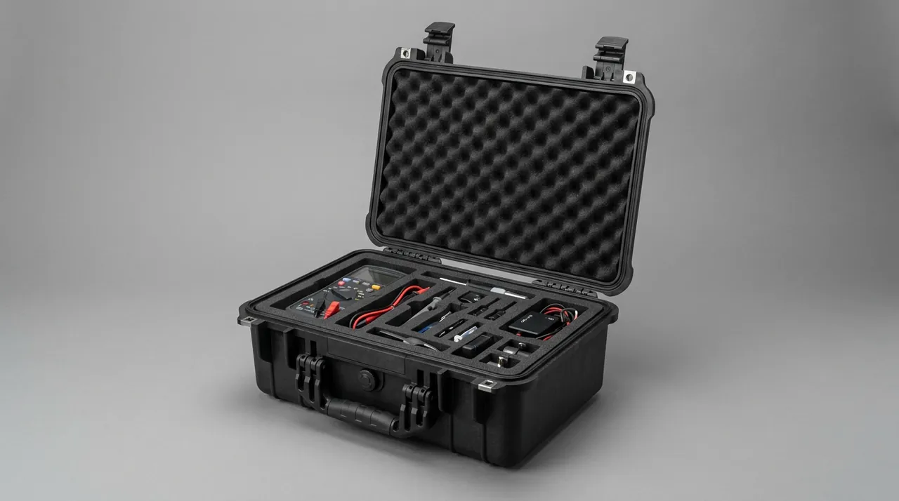
12. Operating and maintenance discipline: cleaning, drying and re-inspection
Even a well-built case depends on disciplined use. Write the following into the laboratory rotor management SOP:
- Inspect the rotor before packing, confirming no visible impact marks, no residual droplets, and no debris in the tube bores.
- Seat the rotor in the marked orientation and position. Never force it in or insert it at an angle.
- Place buckets, lid and seals in their own positions with no overlapping loads.
- Close all latches before closing the lid and confirm no foreign object is trapped in the gasket.
- Inspect after every trip, focusing on insert cavity compression marks and any new marks on the rotor rim.
- Clean the insert quarterly. Wipe closed-cell foam with a mild detergent and let it air dry in the shade. Never sun-dry or oven-dry.
- Verify the component list after every transfer and trace any missing item within 24 hours.
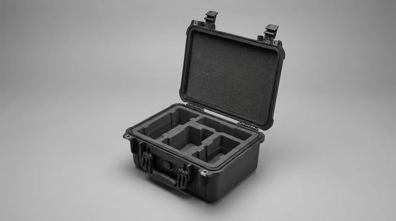
General guidance on cleaning agents and foam care is in how to clean a protective case. Age-related performance degradation and replacement timing are covered in protective case service life.
One further point: the rotor's own inspection interval is set by its manufacturer, usually by run count or calendar age. Packaging reduces the probability of damage but never replaces the mandated periodic inspection. Keep a rotor log inside the case recording each transfer date, route and post-trip inspection result so the traceability chain is complete.
13. Customization workflow and OEM/ODM collaboration
A rotor case is a made-to-order product; standard cases rarely fit directly. A repeatable customization workflow looks like this:
- Information gathering. Provide the rotor model, nameplate photo, external dimensions, and 3D data or a point cloud for the critical fit areas. Without drawings, measure outer diameter, height, taper angle and bore pattern with calipers and photograph the front and side views.
- Insert modeling and layout. Plan the cavities from the component list and decide whether the case must also hold buckets, adapters and a seal cell.
- Material and structure confirmation. Fix the shell material, sealing class, number of latches, and whether a pressure equalization valve and desiccant bay are needed.
- Prototype and trial fitting. Always trial-fit the first article physically. Check ease of loading, rotor-to-cavity clearance, and remaining clearance after the lid closes.
- Validation and volume production. Move to serial production after drop and vibration validation, with AQL sampling.
JUNZHIJIA, manufactured by Kexin New Materials (Guangdong) Co., Ltd., supplies rotor component cases with rotor-specific lofted inserts, swappable module base plates, and case-plus-insert kits. OEM/ODM support covers dimensions, color, silk-screen printing and marking. For buyers who require acceptance documentation, rotor insert material declarations, cavity dimensional inspection records and transport test reports can be provided as agreed. Sampling and judgment methods for first-article acceptance are in custom case acceptance and AQL.
14. Purchasing acceptance checklist and common misconceptions
Check each of the following at acceptance and require corrective action before volume delivery if any item fails:
- Is the clearance between the cavity and the actual rotor within 0.5 to 1.5 mm?
- Do the restraint layer hardness and density match the sample, verified with a durometer on a spot check?
- Is there a visible gap after the lid closes, and is the gasket continuous with no breaks?
- Do the number and retention force of the latches support a fully loaded lift?
- Is handle or lift-point deflection acceptable under full load?
- Are model, serial number and orientation marked on the insert surface?
- Is a pressure equalization valve fitted? This is mandatory for altitude crossing or air freight.
- Are a desiccant bay and a humidity indicator card provided for?
- Is the shell free of sink marks, warping and flash?
- Are material records, dimensional records and test reports complete?
Five misconceptions come up repeatedly. First, the belief that harder is safer. A rigid insert transfers impact directly into the rotor and is actually more dangerous. Second, replacing a form-fit insert with air pillows. Air pillows absorb a single impact but do not restrain sustained movement. Third, transporting the buckets on the rotor. Fretting between trunnion pin and bore is irreversible. Fourth, ignoring seal storage orientation. O-rings held under compression take a permanent set. Fifth, evaluating the shell and ignoring the insert. The insert, not the shell, decides whether protection works.
Where a buyer also handles other precision instruments, the balance between universal cases and dedicated inserts is discussed in the instrument case selection guide, and foam trade-offs are compared in case foam material comparison.
Frequently Asked Questions
Q: Can the original factory shipping carton keep being used as a daily rotor transfer case?
A: The factory carton is designed for one long journey or a small number of them, and its internal foam usually takes an unrecoverable compression set after a single full shipment. Continuing to use it creates two distinct problems. First, the clearance between cavity and rotor grows and restraint effectively disappears, so every later trip adds a little more relative movement and a little more unbalance. Second, corrugated board loses strength rapidly once it absorbs moisture, so stacking capacity becomes unreliable in a humid warehouse or a cold-chain corridor. Treat the factory carton as a transition package only, and move to a reusable rigid case as soon as incoming inspection is passed. If budget is genuinely constrained, at minimum replace the insert with a fresh one and add a humidity indicator card so the interior condition can be read without opening. For high-value or ultracentrifuge rotors, a model-specific case usually pays for itself, because one return-to-factory inspection often costs about as much as the case itself, and the downtime while waiting is normally the larger cost.
Q: Should the rotor lid and the buckets be removed before transport?
A: Both should be removed and packed separately. Buckets connect to a swing-out rotor through trunnion pins, and transport vibration causes fretting between pin and bore. That wear is irreversible, and accumulated over a few dozen transfers it changes the swing-out angle and the balance state, so buckets belong in their own restrained bays. The lid is a slightly different case. Quick-lock catch tabs are thin-walled load-bearing features, so if the lid stays closed during transport, impact load travels through the lid body into the catches and can deform or fracture a tab. If the lid is removed instead, keep the sealing face up and away from hard components so the machined land is not scored. The practical conclusion is to remove both, provide a dedicated lid bay and a dedicated bucket bay, and separate them with a divider so they cannot strike each other in transit. Label each bay so the operator cannot reassemble the package incorrectly.
Q: The rotor looks undamaged after transport. How can I tell whether it is still usable?
A: A clean exterior is not evidence of usability, because loss of balance usually comes from internal or microscopic plastic deformation rather than from a visible crack. A workable sequence has three steps. First, inspect the critical mating surfaces: the taper, the spindle seat, the lock thread and the walls of every tube bore. Use a flashlight at a shallow angle, which reveals bright marks, galling and press marks that disappear under diffuse light. Second, check for new scratches or rim burrs and compare the rotor against photographs taken before packing. Third, after reinstallation run the rotor at low speed and compare vibration and noise against the historical record before stepping up, stopping immediately if anything is abnormal. If the case was dropped or the insert shows clear displacement marks, the safest course is to return the rotor to its manufacturer for inspection rather than deciding by feel or by schedule, because a rotor that passes a visual check can still be outside its balance tolerance.
Q: Should a desiccant be fitted inside the case, and how should it be managed?
A: Yes, particularly for aluminum and ultracentrifuge rotors. Aluminum is susceptible to stress corrosion cracking when chloride ions and residual tensile stress combine, and moisture is the vehicle that transports chloride ions to a crack tip, so holding internal relative humidity below 40 percent has a clear engineering basis rather than being a general precaution. Use a replaceable silica gel pack sized at roughly five to ten percent of the case's internal volume, and attach a humidity indicator card to the inside of the lid so status can be read without opening the case. Manage it on a fixed replacement interval, because saturated silica gel not only stops absorbing moisture but can release it back into the interior. Label the outside of the case with the last replacement date. For cases held in long-term storage without use, open and air them every three to six months and fit fresh desiccant at the same time.
Q: What additional material requirements apply to a rotor case used in a clean laboratory?
A: The core requirements are low particle shedding and wipe-down disinfectability. The insert must be closed-cell foam. Open-cell foam sheds continuously during use, and once it has absorbed culture media or blood fractions it cannot be fully cleaned, so it becomes a persistent contamination reservoir. Do not place cardboard, wooden blocks or corrugated pads inside the case, because fibrous materials are simultaneously a particle source and a moisture source. Design the insert as a module that lifts out in one piece so it can be cleaned, disinfected and dried separately before being refitted. Case and insert surfaces should tolerate repeated wiping with seventy percent ethanol, isopropanol and quaternary ammonium disinfectants without cracking or losing gloss, and the shell should be free of deep recesses where liquid can pool. Where the environment also requires static control, specify modified materials with surface resistivity between 10^6 and 10^9 ohms to reduce particle attraction, and confirm the value on a test report rather than on a datasheet claim alone. See ESD shielded case design for related structural detail.
Q: Do scratches on the shell affect protection performance?
A: It depends on location and depth. General scratches on a side wall or the base have almost no effect as long as they do not penetrate the wall thickness and do not extend into the gasket sealing land. Trim any raised edge with fine abrasive paper and continue using the case. Scratches in the gasket groove, at a latch mounting seat, at a hinge root or near a lifting aperture need careful evaluation instead. A scratch in the gasket groove can become a leak path for splashing water and for condensation. A scratch at a latch or hinge root may come with stress concentration that grows under repeated cycling. A scratch at a lifting aperture is directly relevant to lifting safety with a fully loaded case. A practical test is a simple water spray: close the case, spray from all directions for five minutes, dry the exterior, then open and check the inner wall and insert for water traces. Any trace means the seal has failed and the case or gasket needs replacement.
Q: Can one case hold several rotor models at the same time?
A: Yes, but it requires a swappable module base plate rather than a fully form-fit cavity. A form-fit cavity is molded around one rotor outline and cannot be reused when the model changes, so it only makes sense for a single-model, high-volume laboratory. A swappable module design makes the base plate a standard grid, with restraint modules manufactured per model and located into the plate, so one case serves several rotor types. Three constraints apply. First, weight differences between models change the center of gravity, so place the heaviest rotor near the middle and close to the handle, and check the lift by hand before shipping. Second, modules must have a reliable anti-lift feature so they cannot be pushed out of the plate in transit. Third, every module set needs its own identifier and the case needs a configuration list, otherwise mismatching becomes common after a few months of use. A typical arrangement covers three to five common rotors with one or two spare positions for expansion.
Q: How should the protection performance of a custom case be verified on a real route?
A: Use a two-stage approach that combines design validation with field validation. Design validation happens at the prototype stage and follows standard procedures for drop, random vibration and stacking, ideally at a third-party laboratory, to confirm that the insert cavities do not collapse and that the rotor does not shift under load. Field validation supplements it on the real route. Place shock and vibration recorders inside or on the case, record acceleration peaks and spectra for the whole journey, and compare the recovered data against the design assumptions when the shipment arrives. Focus on three things: whether peak acceleration exceeds the energy absorption range the insert was designed for, whether dominant vibration energy falls near the natural frequency of the packaging system, and whether the insert develops permanent compression after repeated trips. Data accumulated this way also feeds back into insert thickness and material selection. See ISTA transport testing procedure for the underlying validation logic.
Conclusion and Further Reading
A rotor case succeeds on three points, none of which is shell thickness: locking the rotor into position, holding the interior within temperature, humidity and cleanliness limits, and separating components by failure mode. Get those right and silent transport damage falls sharply. Start from your rotor list when specifying.
Further Reading