


An autoclave is critical equipment in pharmaceutical, medical device, food processing and laboratory operations, and the hardest parts of it to ship are not the outer panels but the chamber, door gasket, seals, relief valve and vacuum pump parts that decide whether the machine will hold pressure. Once a sterilisation chamber becomes oval in transit, the door gasket can no longer seal evenly and the cycle starts failing on pressure hold; once a sealing face is scratched or iron-contaminated, steam penetration and vacuum leakage become long-term problems, so a case for these parts has to deliver four things at once: resistance to deformation, sealing face protection, cleanliness control and moisture control. Sterilisation chambers are usually thin-wall 316L vessels with wall thickness commonly in the 3 to 6 mm range, and their resistance to external pressure and local crushing is far lower than their resistance to internal steam pressure, so the way the case supports them decides whether self-weight, clamping bands and stacking will flatten them. This article works through chamber, door gasket, seal ring, relief valve and vacuum system parts, and gives executable practice for structure, inserts, clean packaging and acceptance.
Delivery timing for these parts is often the most awkward part of the project. The machine frame is still being installed while the chamber and gaskets have already arrived, sitting in a plant warehouse or an ordinary store outside the clean zone for weeks. By the time pressure hold and vacuum leak rate tests are run during commissioning, liability can no longer be established. Writing protection requirements into the purchase contract and moving acceptance actions forward to the moment of unpacking is the practical problem this article addresses.
Contents
- Why Autoclave Components Keep Coming Back for Rework After Shipping
- The Sterilisation Chamber: Ovalisation and Denting in Thin-Wall Stainless
- Door Gaskets and Seals: Compression Set in Silicone and PTFE
- Relief Valves and Vacuum System Parts: Set Pressure and Seal Integrity
- Cleanroom Context: GB 14881, GMP and ISO 14644 Packaging Requirements
- Passivated Stainless Surfaces and Chloride Contamination Control
- Chamber Deformation Control: Support Rings, Bands and Internal Bracing
- Sealing Face Protection: Films, Guard Rings and Scratch Prevention
- Moisture, Mould and Desiccant Sizing
- Case Structure and Rigging: Constraints in Pharma Plants and Hospitals
- Test and Verification Basis: ISTA, GB/T 4857 and GB/T 191
- Unpacking Acceptance and On-Site Assembly Handover
- Component Case Selection Checklist and Three Misconceptions
- Frequently Asked Questions (FAQ)
- Conclusion and Related Reading
Why Autoclave Components Keep Coming Back for Rework After Shipping
A large pre-vacuum autoclave has a long parts list: chamber and jacket, door body with hinge mechanism, door gasket in silicone or PTFE-clad form, relief valve and pressure gauge set, vacuum pump, condenser and steam trap, internal trolley and shelving, control cabinet and sensors. These travel in three legs: factory to contractor or distributor warehouse, warehouse to the user's plant, and plant to the clean zone entrance. The first two legs are ordinary logistics. The last is the shortest and also the one handled most casually and causing the most concentrated damage.
Rework clusters into five observable patterns. First, chamber ovality or flatness out of tolerance, so that door closing produces uneven compression and the pressure hold test starts losing pressure during the heating phase. Second, marks, local thinning or distortion in the door gasket, presenting as leak points that are hard to localise and usually ending in a full replacement. Third, scratched sealing faces and broken passivation, covering flange faces, O-ring grooves and valve seats, where a light rust spot is easily dismissed at acceptance as a cosmetic issue even though it is the starting point for later chloride pitting. Fourth, broken relief valve seals or drifted set pressure, which forces re-calibration before the valve can pass validation. Fifth, emulsified vacuum pump oil or contaminated pipework, which lengthens the pre-vacuum cycle and cuts steriliser throughput.
All five share one timing characteristic: they almost never appear on the day of delivery. A chamber that looks perfect may already have sub-millimetre ovality from sagging under its own weight, and that deviation only surfaces at full-load pressure hold or vacuum leak testing. The value of a protective case therefore lies not in visible protection but in ensuring the part still holds its as-built geometric accuracy and surface condition at the moment the case is opened.
The Sterilisation Chamber: Ovalisation and Denting in Thin-Wall Stainless
The construction of a sterilisation chamber makes its packaging requirements quite different from those of other equipment parts. To control thermal stress and total mass, chambers are generally thin-wall welded stainless structures, with cylindrical shell walls commonly 3 to 6 mm thick and rectangular chamber plates thinner still but stiffened by ribs. A thin-wall cylinder carries internal pressure well, yet is fragile against external pressure, local crushing and concentrated end loads.
| Typical defect | Main cause | Consequence |
|---|---|---|
| --- | --- | --- |
| Ovality out of tolerance | Single or two-point support, over-tightened bands, stacking load | Uneven gasket compression, failing pressure hold and leak rate |
| Local denting of the shell | External impact, over-tight strapping, bearing against a sharp edge | Trolley entry obstructed, higher pitting and cracking sensitivity |
| Warped end flange face | Lifting slings attached to the flange, impact on landing | Door misalignment, premature hinge and locking wear |
| Micro-cracks in welds | Repeated bending vibration, lifting shock | Long-term leak path, invisible to visual inspection |
| Bulging of rectangular walls | No internal bracing, external compression | Discontinuous gasket contact band, seal failure |
The first packaging principle is to let the chamber carry load in its stiffest direction. A cylindrical chamber should stay with its axis horizontal, with the weight distributed through rigid end-face support plus multiple conformal supports along the middle, no fewer than four support points, and every contact made as area support. Straps or clamping bands must never be tightened directly around the mid-section of the shell; a thin wall dents immediately under a concentrated force, and any dent that forms traps rinse water during later cleaning and becomes the starting point for pitting.
The second principle is to prohibit stacking above the chamber. The chamber itself lacks the stiffness to carry other cases, and where site constraints force stacking, the case's own rigid frame should carry that load directly to the floor rather than through the chamber wall. This is most often missed during storage, because a warehouse operator only sees a flat case that looks stackable.
Rectangular chambers need internal bracing in addition to external frames and bands. The practice is to insert removable brace bars or plates inside the chamber along its long axis, propping the two large opposing faces apart so that vibration and external stacking loads cannot produce permanent bulging. Bracing must be easy to remove, must never be welded to the wall, and must have smooth burr-free surfaces so it cannot scratch the interior before installation.
Door Gaskets and Seals: Compression Set in Silicone and PTFE
The door gasket is the most sensitive part of an autoclave and the one most easily damaged by packaging method. It works under continuous compression, and continuous compression is also the normal state during shipping and storage, which makes compression set the dominant failure mode.
Silicone gaskets are elastic, recover quickly and cost less, and they dominate in medical and pharmaceutical sterilisers, but they carry clear storage conditions: avoid prolonged high temperature, avoid direct sunlight, and avoid sharing a room with ozone sources such as motors and welding operations. PTFE-clad seals have a low friction coefficient, a wide temperature range and low adhesion to soil, and are common on doors that open frequently or run dry heat cycles, but PTFE cold-flows, so it slowly loses thickness under sustained pressure.
| Seal material | Temperature suitability | Compression set tendency | Packaging and storage notes |
|---|---|---|---|
| --- | --- | --- | --- |
| Silicone (VMQ) | Wide, suited to steam service | Moderate, strongly time and temperature dependent | Lay flat or hang at large radius, avoid light and ozone, never store compressed |
| EPDM | Good against steam and hot water | Low to moderate | Keep away from mineral oils and solvents |
| PTFE-clad | Very wide | Cold flow rather than loss of recovery | Avoid small-radius bends and sharp contact, store flat |
| FKM | High temperature and media resistance | Low | Higher cost, avoid ketones and esters |
| NBR | Moderate | Moderate | Not recommended for long-term steam service |
Five packaging rules follow. First, do not ship the gasket installed on the door. Shipping with the door fitted means the whole seal stays compressed for weeks, which is the direct cause of compression set; remove it, pack it separately, and install on site. Second, lay a single gasket flat or hang it at a radius no smaller than the maker specifies, because a sharp fold leaves a crease whose recovery cannot be restored. Third, never store gaskets in the same compartment as sharp metal parts, since a single cut in the sealing lip will fail a leak test. Fourth, control temperature and humidity inside the packaging, because a sea container can run far above ambient and accelerate ageing when gaskets share a closed space with metal parts. Fifth, label the production batch and pre-installation inspection requirement so the site can judge whether the storage period has expired.
Spare seals shipped with the machine are best packed individually in sealed bags with desiccant and placed in a divided compartment, rather than tucked inside the chamber for shipment, since interior bracing and residual moisture are both hostile to elastomers. For the general method of selecting seal materials and setting compression, see gasket material selection and compression design.
Relief Valves and Vacuum System Parts: Set Pressure and Seal Integrity
A relief valve sits on the pressure boundary, and what shipping threatens is not its mass but the irreversibility of its state. Set pressure results from spring preload combined with the disc geometry, and strong vibration or impact in transit can alter preload or shift the disc relative to its seat. Once the seal is broken or the set point drifts, the valve must go back for re-calibration with freshly signed records. Relief valves should therefore be removed and packed separately rather than shipped mounted on the chamber. In their own case, use a conformal insert to limit movement, blank off or cap the ports, orient the stem as the maker requires, and keep the valve out of any compartment holding heavy items.
Vacuum system parts include the vacuum pump, condenser, steam trap, vacuum pipework and associated valves. Their common requirement is cleanliness. A vacuum pump has extremely small internal clearances, and particles or rust flakes drawn in from pipework will score the pump chamber, so every opening must be plugged and port caps should stay in place until installation. For oil-lubricated pumps, confirm oil level and oil condition before shipping and prevent tilt in transit from pushing oil into the gas path. Where a hydraulic or lubricating circuit has a defined cleanliness requirement, use the ISO 4406 particle contamination code system to agree the as-delivered state and the acceptance method, so that the particle contamination class on arrival becomes a testable clause.
Valve-type parts packed on their own are best positioned in divided compartments with ports facing up and blind plates fitted, following the same logic as our notes on restraint and marking practice for pressure vessel component cases. Condensers and heat exchange parts are heavy, so the case base needs enough rigidity to resist flexing during a lift, which would otherwise let the part move and strike its own connections.
Cleanroom Context: GB 14881, GMP and ISO 14644 Packaging Requirements
End users of autoclaves usually operate in regulated environments: food businesses follow the general hygiene requirements of GB 14881, pharmaceutical manufacturers follow clean zone classification under good manufacturing practice, and medical device and laboratory users commonly reference the ISO 14644 cleanliness classification. This means packaging is not merely a logistics container but the first contamination barrier at the clean zone entrance.
| Scenario | Primary constraint | Packaging response |
|---|---|---|
| --- | --- | --- |
| Food plant (GB 14881 context) | No contamination introduced at food contact surfaces, humid production halls | Wipeable case, non-shedding liner, no mould risk |
| Pharma clean zone (GMP context) | Zoned management and material transfer flow, packaging must not be a contamination source | Double packaging, outer layer stripped before transfer hatch or air shower |
| ISO 14644 cleanroom | Particle and microbial control | Clean bag inner packaging, exposed stripping line, low-outgassing materials |
| Aseptic filling support equipment | High surface cleanliness and cleanability | Protective film stripped last inside the clean zone, no chlorine-bearing consumables |
The most effective practice on site is double packaging with peel-off opening. The part is packed in the clean environment into an inner barrier (clean bag or foil laminate bag with desiccant), and that is then placed inside an outer protective bag and the case. At the clean zone entrance, the outer layer is stripped first; the part enters through the transfer hatch or air shower still inside its inner layer; the inner layer is finally removed at the installation position. This protects the part and also prevents dust picked up in transit from being carried into the clean zone.
Packaging materials must meet two requirements together: no shedding and no outgassing. Wooden crates grow mould and shed particles in humid conditions and are usually unwelcome inside a clean zone, and paper labels are hard to clean inside a transfer hatch. A better combination is a plastic or aluminium case with a wipeable liner, labelling in synthetic material or engraved directly into an aluminium plate, and rounded internal corners that do not trap dust. For cleaning methods and detergent selection in clean environments, see cleaning and maintenance of protective cases. Where parts support an aseptic filling line, the packaging logic closely matches the clean transport requirements for aseptic filling equipment cases.
Passivated Stainless Surfaces and Chloride Contamination Control
Stainless steel resists corrosion because of a very thin chromium-rich passive film on its surface. In transit and storage that film is most easily destroyed by three things: mechanical scratching, iron contamination and chloride.
Mechanical scratching usually comes from hard particles in packaging materials, unwrapped tools, and burrs on metal parts inside the case. The remedy is a soft pad at every stainless contact point and a ban on wire brushes, abrasive paper and metal scrapers inside the case.
Iron contamination is the most insidious. Carbon steel swarf, flaking from zinc-plated parts and even grinding dust settling on stainless steel create a micro-cell in humid conditions: rust spots appear around the iron particles first and pitting follows. Risk rises on sea passages and in coastal storage, so organise transport validation using the transport packaging test logic of the GB/T 4857 series and use GB/T 10125 salt spray testing as a supplementary corrosion check. A colour reaction test for free iron can be run on site as part of unpacking acceptance.
Chloride is dangerous because it triggers pitting and stress corrosion cracking, and it is especially aggressive where temperature rises and residual stress remains, such as welds and formed bends. Packaging consumables must therefore exclude chlorine-bearing materials: ordinary PVC film contains chlorine and plasticiser and should never contact stainless surfaces directly, and chlorine-bearing detergents and label adhesives are equally prohibited. Use polyethylene or polyester protective film, peelable film made for stainless service, and chlorine-free cushioning. Vapour phase corrosion inhibitors work well on carbon steel but should be adopted cautiously around stainless and clean environments, and only after a compatibility trial.
| Contamination type | Typical source | Visible result | Countermeasure |
|---|---|---|---|
| --- | --- | --- | --- |
| Iron contamination | Carbon steel fixtures, plated parts, grinding dust | Local rust spots, pits | Stainless tooling throughout, free iron colour test at unpacking |
| Chloride | PVC film, chlorinated detergent, chlorinated tape | Pitting, crevice corrosion | Switch to PE or PET film, chlorine-free detergent |
| Mechanical scratch | Burrs, hard particles, bare tools | Linear scratches, cut sealing faces | Soft padding, deburring, dedicated tools |
| Water marks and mould | Humid environment, container rain | Staining, mould spots, odour | Desiccant, sealed inner bag, humidity indicator card |
Chamber Deformation Control: Support Rings, Bands and Internal Bracing
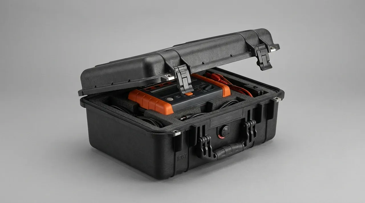
Deformation control comes down to converting point load into area load and single-point support into multi-point support.
Support rings are the first choice for cylindrical chambers. Fit rigid rings, made from plywood, aluminium profile or rigid PVC, around the shell near the end flanges or at defined stations, with a soft pad between ring and shell, so the rings take the bending moment from lifting and vibration while the shell sees only uniform radial pressure. Ring count and position follow the length-to-diameter ratio: the longer and slimmer the chamber, the more closely spaced the supports must be.
Clamping bands are for limiting axial and lateral movement only, never for carrying load. Three conditions apply whenever a band is used: the soft liner beneath it must be wide enough to spread pressure, the band must avoid welds and nozzle openings, and tightening torque must stop at the point where no visible mark appears. Field experience favours adding more conformal foam pads instead of tightening a band harder to stop movement.
Internal bracing serves rectangular chambers and large flat panels. Removable brace bars or plates prop the two opposing faces apart from inside, turning external load into internal compression. Bracing must be easy to install and remove, unwelded, burr-free, and listed as a separate line on the packing list so that nothing is left inside at installation. The point at which bracing is removed also belongs in the work instruction: everything must come out before the first heat-up cycle.
Attitude and lifting affect deformation too. The chamber should travel in its as-built horizontal attitude, since long-term vertical storage puts the whole mass on the end flange and warps it. Lifting points belong on dedicated lifting eyes or a rigid frame rather than on flanges, and synthetic slings with corner protectors should be used, with the sling angle kept from opening too wide so that horizontal force does not crush the shell. The stiffness of the case floor and support frame must be calculated, because a case that flexes when lifted shifts the support points and effectively converts area support back into point support. For calculating liner density and structural combinations, see cushion liner and case structure design and comparison and selection of liner materials.
Sealing Face Protection: Films, Guard Rings and Scratch Prevention
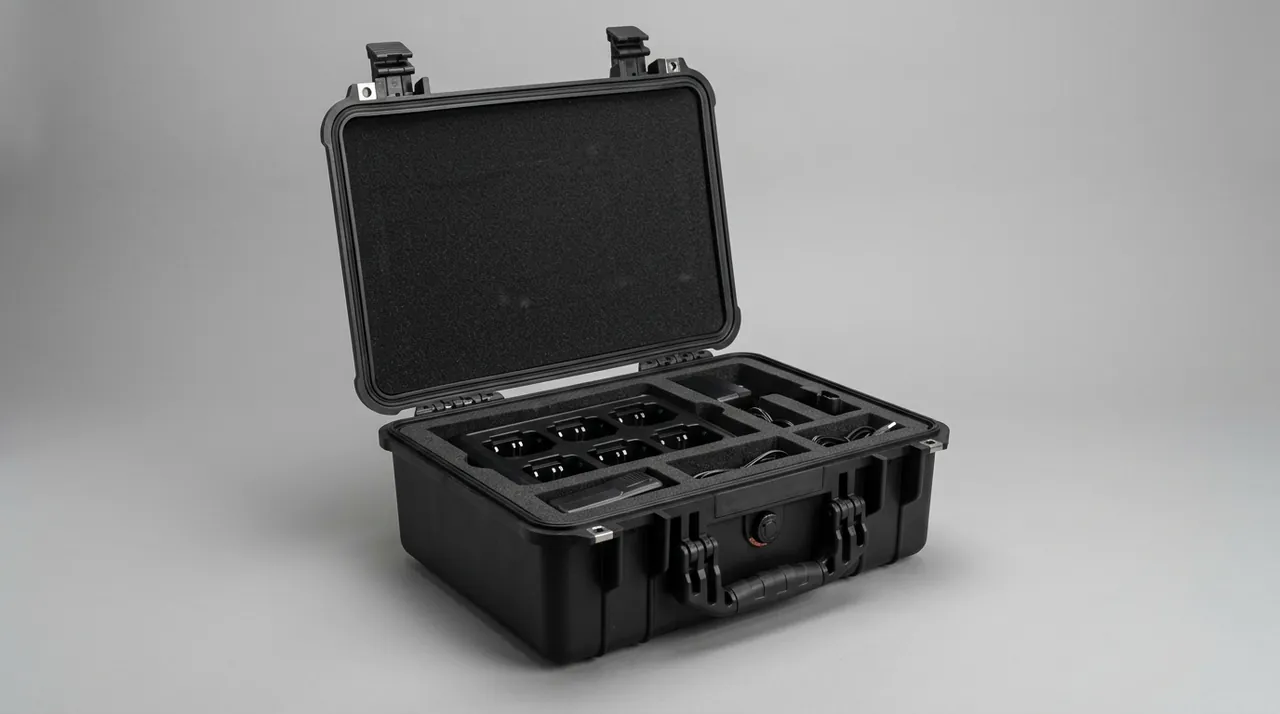
Sealing faces include the door seal groove, the chamber door frame sealing face, flange faces, O-ring grooves and valve seats. They share one geometric feature: narrow-band contact, where a very small scratch or a single foreign particle creates a leak path. The protection strategy is therefore not to wrap them up but to isolate contact and defer removal to the last moment.
Step one is cleaning and confirmation. Sealing faces should be cleaned and dried before packaging, and confirmed free of burrs, machining residue and free iron. Any scratch that already exists before packing must be recorded and photographed, otherwise it cannot be distinguished from damage that occurred later.
Step two is film application. Apply peelable protective film in PE or PET continuously along the sealing face, pressing the edges down without stretching, since tension makes the film retract. Chlorine-bearing PVC film is prohibited. For grooves, fill the groove with a soft filler strip first and apply the film over it so the groove edge cannot cut through.
Step three is guard rings. Door bodies and chamber door frames present protruding geometry that easily contacts other objects in transit, so fit plastic guard rings or soft corner guards. Their purpose is to move impact energy away from the sealing face.
Step four is port blanking. Fit blind plates or dust caps to every nozzle, instrument connection and vacuum port, and list them as separate attachment lines on the packing list. Blanking hardware must not become a new contamination source, so specify stainless or plastic.
Step five is discipline. On site, do not use metal scrapers, screwdrivers or blades against the sealing face to remove film. Film should be removed at the installation position, inside the clean zone, at the last moment, followed immediately by a surface check and assembly within the specified time. Wear clean gloves when touching stainless sealing faces, since chloride in perspiration can seed pitting.
Moisture, Mould and Desiccant Sizing
Autoclave parts are sensitive to moisture for three reasons. First is the corrosion risk on stainless surfaces: where free iron or chloride is present, humidity is the catalyst for pitting. Second is mould and ageing in non-metallic parts: silicone and some rubber grades readily take up moisture in hot humid conditions, and long storage can bring surface mould and hardness change. Third is electrical and instrument parts: pressure transmitters, temperature probes and solenoid coils drift or malfunction after taking on water.
Control measures rank as follows.
- Sealed inner packaging. Seal the part first in a clean bag or foil laminate bag with desiccant and a humidity indicator card, forming the first barrier. The case itself can be designed and verified to IP67 under GB/T 4208, which corresponds to IEC 60529; see how IP ratings are achieved in protective cases.
- Sized desiccant. Calculate molecular sieve or silica gel quantity from the free volume inside the bag and the expected storage duration, with a safety margin. Desiccant should be bagged in a breathable sachet inside the clean environment and secured so loose beads cannot reach a sealing face.
- Pressure equalisation. A fully sealed case develops a pressure differential in air freight or high-altitude road transport, so fit a hydrophobic breather valve to avoid difficult opening and a flattened gasket.
- Mould prevention. Avoid direct contact between paper or timber inner packaging and stainless parts; paper grows mould in humid conditions and the mould then contaminates the surface. Substitute PE bags and keep a humidity indicator card inside the case.
- Container rain prevention. In sea freight the day-night temperature swing inside a container condenses water on the roof and drips it onto cargo, so add a drip liner inside the case or a rain cover outside.
One reminder: desiccant is a consumable with a finite capacity. A long sea passage plus on-site storage often exceeds two months, so the plan must state replacement intervals and assign responsibility, because fitting desiccant is not the same as staying dry throughout.
Case Structure and Rigging: Constraints in Pharma Plants and Hospitals
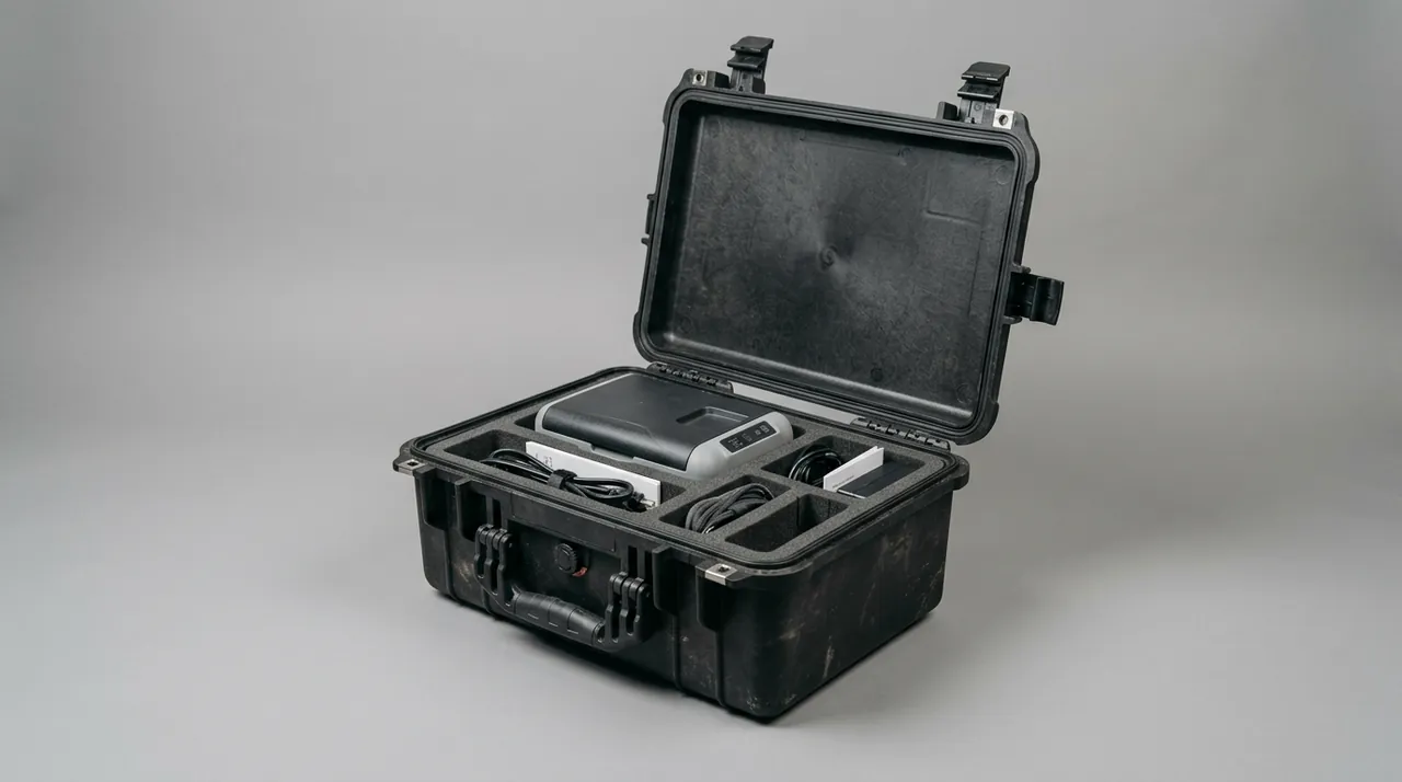
The final installation point determines that the case cannot be designed to logistics standards alone.
The clean zone entrance is a hard constraint. Pharmaceutical sites move material into clean areas through transfer hatches, air showers or material airlocks whose dimensions are usually far smaller than an ordinary doorway. Case outline must therefore be based on measured net width, net height and load capacity of those routes, and the inner package dimensions must be a design input, not just the outer case. If the inner package cannot pass a transfer hatch, the design must allow the shipment to be split into pieces that can.
Wooden packaging is usually not accepted inside a clean zone. Crates grow mould and shed particles, and GMP material transfer flows often require them to be stripped or refuse them entry. A better choice is a plastic or aluminium case with a wipeable liner and rounded internal corners that can be wiped with detergent before entry. Because pharmaceutical plant equipment such as pharmaceutical filling line component cases faces the same constraints, clean zone access should be treated as a general design input.
Rigging design points. Fit a lifting eye at each of the four corners, placed symmetrically about the centre of gravity, with the eye-to-case connection sized to a load factor of no less than 4:1. Add forklift pockets in the base and engrave centre-of-gravity and lifting point markings. For very long chamber cases, add an intermediate lifting point so the case itself does not flex during the lift. Sites normally need a hydraulic lift table working with a small mobile crane, and the work should come under the plant permit-to-work and cordon arrangements. After unpacking, move parts on a dedicated trolley with conformal support rather than pushing them on a pallet, which puts point loads on the shell. For case hardware reliability see hinge, latch and seal structure design for toolboxes and the instrument case selection guide.
Test and Verification Basis: ISTA, GB/T 4857 and GB/T 191
The verification principle for autoclave component cases is that transport testing proves the structure, clean testing proves the inner packaging, and material testing proves compatibility. None substitutes for another.
| Standard or document | Coverage | Notes |
|---|---|---|
| --- | --- | --- |
| GB/T 4857 series | Drop, stacking, random vibration, shock | Select combinations by transport leg; focus on proving no deformation under stacking |
| ASTM D4169 | Distribution cycle assurance | Often cited for sea plus inland combinations |
| ISTA 3A / 3E | Parcel and unitised transport tests | Applies to air or less-than-truckload scenarios |
| GB/T 4208 / IEC 60529 | Enclosure ingress protection | Confirms sealing of case and inner bag |
| GB/T 10125 | Salt spray testing | Corrosion verification for sea freight and coastal storage |
| GB/T 191, GB/T 13384 | Packaging markings and general rules for mechanical and electrical products | Centre of gravity, lifting points, moisture protection, stacking limits |
| ISO 14644 series | Cleanroom classification | Basis for clean zone material transfer and inner packaging operations |
| ISO 4406 | Particle contamination class for fluids | Agreed as-delivered cleanliness for vacuum and lubrication circuits |
| UL94 | Flammability rating for plastic materials | Self-assessment of liners and plastic parts |
| MIL-STD-810H | Vibration, shock, temperature and humidity methods | Used as an environmental test method reference only, not a military certification |
One point deserves emphasis: vibration verification for chamber-type parts cannot be judged only by whether the case survived. The correct criterion is to place measurement points on the chamber itself and use the change in ovality or flatness before and after transport, rather than simply checking the case for damage. Stacking tests matter just as much, because many deformation problems do not come from a drop but from two cases being stacked in a warehouse for three months. Test reports should record measurement positions, instruments, environmental conditions and acceptance criteria so they can serve as purchase acceptance evidence.
Unpacking Acceptance and On-Site Assembly Handover
Unpacking is a sequenced technical operation. When parts must enter a clean zone, the wrong sequence contaminates both the part and the environment.
- Read the environmental record first. Export the in-case temperature and humidity logger data before opening and check for any excursion; check whether the humidity indicator card and tilt indicator have changed colour.
- Strip the outer packaging outside the zone. Complete outer packaging removal outside the clean zone entrance on a clean transition mat, leaving transit dust outside.
- Inspect the case and part externally. Record dents, deformation and abnormal gasket compression with photographs, and confirm lifting eyes and latches are undeformed.
- Re-measure chamber geometry. Re-measure the internal diameter at both ends, the shell ovality and the flatness of rectangular walls against the factory drawing, and compare with as-built data to judge whether out-of-tolerance deformation occurred.
- Check sealing faces and contamination. Before removing film at the installation position, check the film for damage; after removal check for scratches, foreign matter and rust spots, and run a free iron colour test where needed.
- Count the attachments. Check blind plates, dust caps, bracing, door gasket, relief valve, spare seals and packing list item by item, confirming everything is out, especially bracing inside the chamber.
- Archive records and hand over to installation. File the transport record, unpacking record, measurement data and vendor installation report in one equipment file as part of the validation documentation for later GMP or system audit traceability.
There is only one governing principle: complete the record before disturbing any protection. Once film is removed, the original condition of the sealing face can no longer be proven.
Component Case Selection Checklist and Three Misconceptions
| Check item | What to confirm |
|---|---|
| --- | --- |
| Parts list | Mass and envelope of chamber, door, gasket, relief valve, vacuum pump, condenser, bracing |
| Geometric requirements | Permitted ovality, flatness and flange parallelism, plus the measurement method |
| Cleanliness | Cleanliness class, double packaging format, transfer hatch and air shower limits |
| Sealing faces | Film material with chlorine excluded, guard ring type, removal timing and owner |
| Structure | Case dimension limit, lifting points and forklift pockets, support rings and bands, stacking rule |
| Insert | Material, density, support distribution, displacement clearance, assembly sequence |
| Environment control | Desiccant quantity and replacement schedule, logger, pressure equalisation valve |
| Testing and documents | Standards and items, measurement criteria, packing list, liner drawing, acceptance criteria |
Misconception one: defaulting to a wooden crate. Timber is cheap and easy to work, but it passes poorly through a clean zone entrance, grows mould and sheds in humid conditions, and requires quarantine treatment. When autoclave parts are delivered into a GMP environment, the crate is often stripped before entry, and if the inner packaging was never designed to travel on its own, the part is left exposed at the door.
Misconception two: protecting appearance but not sealing faces. Many cases get thick liners yet let the door sealing face rub directly against foam, or use chlorine-bearing PVC film over it. A sealing face is a functional surface, and both film material and removal timing are specified requirements, not cosmetic considerations.
Misconception three: storing gaskets under compression. Shipping the gasket mounted on the door looks convenient, but it holds the entire seal compressed for weeks and the resulting compression set is unrecoverable. Removing it, packing it flat and installing on site costs less and carries less risk.
Frequently Asked Questions (FAQ)
Q: Why do autoclave chambers deform so easily in transit, and how is ovalisation prevented?
A: The root cause is asymmetry in structural stiffness. To control thermal stress and total machine mass, sterilisation chambers are built thin-wall, with cylindrical shells commonly 3 to 6 mm thick and rectangular chamber plates thinner still. Such a shell carries internal steam pressure without difficulty but resists external local crushing, single-point support and stacking load poorly: as soon as support changes from an area to a point, the shell dents at the contact, and as soon as there are too few supports, a long chamber sags in the middle and its ovality drifts. Prevention reduces to three statements: convert point load into area load, convert single-point support into multi-point support, and let the case frame rather than the chamber carry stacking force. In practice, keep a cylindrical chamber horizontal, support it through rigid end faces plus support rings at intermediate stations, use at least four support points with soft pads at each contact, and use clamping bands only to stop axial movement with torque limited to the point where no visible mark appears. Never stack above the chamber, and where stacking is unavoidable let an external rigid frame carry the load to the floor. Rectangular chambers also need removable internal brace bars propping the large faces apart, all removed before installation.
Q: Should the door gasket be silicone or PTFE, and how is compression set prevented?
A: Silicone and PTFE suit different duty. Silicone (VMQ) is elastic, recovers quickly and has mature steam service history, making it the mainstream material for medical and pharmaceutical steriliser door gaskets, but its compression set is strongly influenced by temperature and the duration of compression. PTFE-clad seals have a low friction coefficient, a wide temperature range and low soil adhesion, which suits doors that open frequently or run dry heat cycles, but PTFE cold-flows and slowly loses thickness under sustained pressure. The decisive action against compression set is actually a disassembly decision: do not ship the gasket mounted on the door. Remove it, pack it separately, and let it stay in a free state for the entire logistics and storage period, installing it on site. Second is storage attitude: lay a single gasket flat or hang it at the large radius the maker specifies, because a sharp fold leaves an unrecoverable crease. Third is environment: avoid prolonged high temperature, direct sunlight and ozone sources such as welding operations or motors sharing the room. Fourth is isolation, since the sealing lip must not share a compartment with sharp metal parts, where a single cut can fail a leak test. Finally, label batch and storage life, and pack spare seals supplied with the machine individually in sealed bags with desiccant.
Q: Does the relief valve need to be removed and packed separately before shipping?
A: Yes, removing it and packing it separately is the lowest-cost prudent option. A relief valve is a protective device on the pressure boundary, and its set pressure results from spring preload combined with disc geometry. Strong vibration and impact in transit can change that preload or shift the disc relative to its seat. If that happens, the valve must go back for re-calibration with newly signed records even when it looks undamaged, and a drifted set point is invisible at delivery acceptance: it only surfaces during overpressure protection validation or an actual discharge. Beyond set pressure, the seal and locking arrangement is equally fragile. Once a seal is broken, the valve legally requires re-calibration, which directly delays steriliser validation and release. The correct approach is to remove the valve from the chamber, pack it on its own with a conformal insert limiting movement, blank off or cap the ports, orient the stem as the manufacturer requires, and keep it away from any heavy item. Give it a fixed position in the case and its own line item so quantities and serial numbers are visible at a glance, and manage it in a separate zone from gauges and sensors. On installation, refit it as the maker requires, verify the seal condition, and file the calibration certificate with the equipment validation documents.
Q: What cleanliness checks should be done on vacuum pump parts after they arrive on site?
A: Cleanliness of the pump and vacuum pipework directly affects pumping speed and ultimate vacuum, and transit plus unpacking is the stage where particle contamination most often occurs. Four checks are worth running on arrival. First, inspect the plugging state: every inlet, exhaust and pipe connection should still have its plug or dust cap in place before opening the case, and any plug found loose or any opening left exposed should be treated as a contamination risk event and recorded. Second, carry out visual and wipe inspection: after removing the plugs, examine the pump chamber walls, pipework bore and valve surfaces with a torch and clean wipes for rust flakes, dust, packaging debris and oil soil, focusing on ports and flange areas. Third, check oil condition and level: on oil-lubricated pumps confirm the level sits within the marked range and that the oil is neither emulsified nor blackened, since tilt in transit can push oil into the gas path, in which case the oil should be replaced and the gas path inspected. Fourth, verify the agreed cleanliness: where a project has a defined requirement, agree the as-delivered state and acceptance method using the ISO 4406 particle contamination code and substitute sampling and testing for subjective judgement. Complete these checks before assembly and file the records in the equipment file, so that any later drop in pumping speed can be compared against a baseline.
Q: What conditions must packaging materials meet in a clean or GMP context?
A: Three conditions matter most: no shedding, no outgassing, and no cross-contamination. Autoclave users often operate in regulated environments, with food businesses following GB 14881 general hygiene requirements, pharmaceutical manufacturers following clean zone classification under good manufacturing practice, and medical device and laboratory users commonly referencing the ISO 14644 cleanliness classification. In a material transfer flow, packaging is treated as an item that can carry contaminants into the area, so it must pass a transfer hatch or air shower, be wipeable, and neither grow mould nor shed particles under the ambient temperature and humidity. Material selection favours plastic or aluminium cases over timber, because crates grow mould and shed in humid conditions and usually require quarantine treatment as well. Liners should be closed-cell foam or moulded parts, avoiding abrasive, fibrous or paper liners in direct contact with stainless parts. Labels should be synthetic or engraved into aluminium plate, since paper labels cannot be cleaned inside a transfer hatch. The most effective practice is double packaging with peel-off opening: the inner layer is applied in the clean environment and removed at the installation position, while the outer layer is stripped outside the clean zone entrance, leaving transit dust outside.
Q: What kinds of damage can occur to passivated stainless surfaces in transit?
A: Four forms dominate. The first is mechanical scratching, caused by hard particles in packaging materials, unwrapped tools and burrs on metal parts inside the case; it appears as linear scratches, and on a sealing face it creates a direct leak path. The second is iron contamination, where carbon steel swarf, flaking from zinc-plated parts or grinding dust settles on the stainless surface and forms a micro-cell in humid conditions, producing rust spots around the iron particles first and then pitting. The third is pitting and stress corrosion cracking driven by chloride, with chlorine-bearing PVC film, chlorinated detergents and chlorinated tape as the common sources, and welds and formed bends where residual stress remains being especially sensitive. The fourth is water marking and mould, arising from humid environments or condensation dripping inside a sea container. Countermeasures are systemic: use stainless or non-metallic fixtures throughout the process, keep grinding operations away from the parts, switch protective film to PE or PET, select chlorine-free detergents, add desiccant and a humidity indicator card to the inner packaging, and run a free iron colour test on critical surfaces at unpacking acceptance. GB/T 10125 salt spray testing can supplement corrosion validation for long sea passages.
Q: The pharma plant or hospital site is tight. How should case dimensions and rigging be planned?
A: Measure the route first, fix dimensions second, and choose rigging method last. Clean zone entrances in pharmaceutical plants usually involve a transfer hatch, air shower or material airlock whose net width, net height and load capacity are often far smaller than an ordinary doorway, so these must be measured and the inner package dimensions used as a design input rather than working from the outer case alone. Hospital constraints come mainly from lift cars, right-angle corridor turns, floor loading limits and shielded doorways. Design responses include removable lids and removable side panels so the part can be lifted out while still supported, avoiding a second handling cycle on the ground; a regular case outline with minimal protrusions; four corner eyes placed symmetrically about the centre of gravity, with the connection sized to a load factor of no less than 4:1; an intermediate lifting point for very long chamber cases so the case does not flex and turn area support into point support; and forklift pockets with engraved centre-of-gravity and lifting point markings. For lifting gear, use synthetic round slings with corner protectors, a compact mobile crane or forklift for the vertical lift, and a scissor lift table for horizontal transfer. Bring all rigging under the plant or hospital permit-to-work and cordon arrangements.
Q: What customisation and documentation can JUNZHIJIA provide?
A: JUNZHIJIA, the protective case brand of JUNZHIJIA, develops bespoke transport cases for autoclave components. On structure, we can calculate support ring count and position from chamber length-to-diameter ratio, wall thickness and mass, along with band liner width and tightening limits and internal bracing for rectangular chambers, and design the case outline and removable structure around the measured plant or hospital route. On inserts, we supply closed-cell foam or moulded conformal support matched to the part outline, with storage positions reserved for bracing and assembly tools. On cleanliness, we configure double packaging with clean bags, foil laminate bags, desiccant and humidity indicator cards, specifying PE or PET film rather than chlorine-bearing material. Documentation can cover packing lists, liner drawings, assembly sequence instructions, material flammability self-assessment and seal class verification records, with third-party transport testing where a customer specifies a standard. Wholesale, distribution and OEM/ODM cooperation are supported, with seal kits and spare part packages configured per project batch.
Conclusion and Related Reading
An autoclave component case delivers more than packaging: it preserves as-built geometric accuracy and surface condition. Deformation control comes from the support method, leak prevention from isolating sealing faces, contamination control from clean materials and double packaging, and corrosion prevention from excluding chloride and iron. JUNZHIJIA builds custom liners, deformation-resistant supports and clean packaging for sterilisation chambers, gaskets, relief valves and vacuum parts.
Related reading