

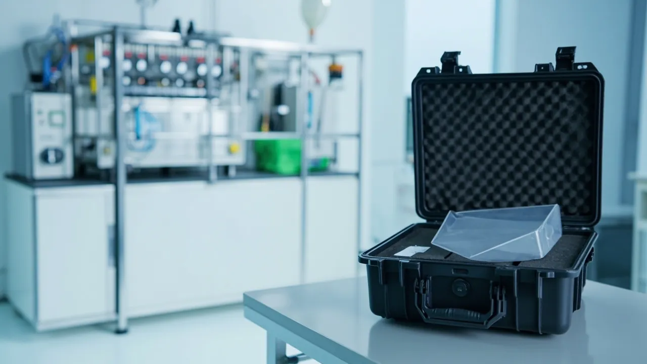
Whether an aseptic filling line starts up clean is often decided not by the machine itself but by one replacement part. A filling valve that drifts on fill volume after replacement, a sterile chamber that fails its pressure hold test after assembly, a gasket that weeps shortly after installation — the origin of problems like these frequently lies not in assembly practice but in the journey the spare made between the factory and the installation point. The transport requirement for aseptic filling components comes down to three rules: cleanliness must not be degraded, sealing faces must sustain no mechanical damage, and any component that contacts product must not be contaminated by non-food-contact materials. Meeting those three rules requires clean-grade liners, a sealable case with controlled differential pressure, and traceable packing and unpacking records — not a thicker cushion.
This article is written for aseptic filling line engineers, packaging hall technical managers and filling equipment manufacturers. It covers protection design for filling valves and sterile components in transit: component grading, the clean chain concept, clean-in-place and sterilize-in-place related parts, sterilant residue, the mapping between cleanliness class and packaging, liner materials, sealing and unpacking procedure, delivery configurations and release acceptance. Standards are cited with their applicable scope so they can be carried into a technical annex. JUNZHJIA practice serves as the manufacturing reference.
Contents
- 1. The clean chain: packaging is its first link
- 2. Filling valves and valve cores: positioning accuracy sets fill volume
- 3. Sterile chambers and isolator components: no foreign matter on sealing faces
- 4. Filling pumps and metering components
- 5. CIP and SIP related parts: spray balls, piping and gaskets
- 6. Sterilant residue and its interaction with packaging materials
- 7. Mapping cleanliness classes to packaging environments
- 8. Liner and case materials: selecting backwards from the cleanliness class
- 9. Sealing, differential pressure and unpacking design
- 10. Delivery configurations and transport validation
- 11. Acceptance and release process
- 12. Customization and compliance documentation
- Frequently asked questions
- Conclusion and related reading
1. The clean chain: packaging is its first link
The quality assurance logic of aseptic filling is a chain: sterilant action, rinse, sterile air protection, filling, capping. If any link fails, the assurance level of the whole chain drops. Spare parts transport matters because it is the earliest link in that chain and the one most often overlooked. If a component is contaminated when it is packed, every downstream sterilization and rinse step has to make up the difference with additional margin, and margin is the least reliable thing there is.
Carrying that chain logic into packaging produces three requirements that must be quantified:
- Entry state. At packing, the component is clean, dry and individually isolated.
- Holding state. In transit, no particles, moisture, fibre or odour are introduced.
- Handover state. At unpacking, the component can be shown to be uncontaminated and every action can be traced.
The third requirement is the one most often skipped and the most valuable. Without records there is no way to tell which link failed, and the next batch repeats the same mistake.
2. Filling valves and valve cores: positioning accuracy sets fill volume
The filling valve is among the most precise spares on an aseptic line. Its function depends on stem travel, seat fit and spring consistency.
| Component | Precision-related feature | Main failure mode | Grade | Key packing action |
|---|---|---|---|---|
| --- | --- | --- | --- | --- |
| Filling valve body | Seat cone, internal flow path | Cone scratching, bore contamination | A | Individual cavity, clean cap on ports |
| Stem and valve needle | Straightness, surface roughness | Bending, scratching | A | Axial location, never left unsupported |
| Seat gasket | Elastomer dimensional stability | Compression set, ageing | A | Flat and tension free, dark, away from oil |
| Springs and return parts | Free length, rate | Deformation under load, mix-ups | B | Individual small cavities, grade marked |
| Flow adjustment parts | Thread or scale precision | Thread galling, scale displaced | B | Thread protector, position locked |
| Tri-clamp fittings | Gasket groove geometry | Deformed clamp seat | C | Segregated, protected against impact |
| Valve manifold block | Multi-port mating faces | Damaged port edges, contaminated channels | A | Cap every port, full-face support |
Grade A parts are those where any surface defect causes functional failure — fill volume deviation, drip, or loss of the sterile barrier. The core packing action is to remove degrees of freedom while protecting sealing faces: locate stems axially and never rest them on their own weight; keep conical faces clear of the cavity wall; never leave springs under sustained compression.
One detail that gets overlooked: if a filling valve stem acquires even a slight bend before assembly, the valve may still actuate after installation while fill volume consistency degrades. This kind of defect is very hard to catch at receiving, and it typically surfaces only when product weight sampling fails, which makes tracing extremely expensive. For stem-type components, inspect straightness part by part and record the result, and pack using an axial support rather than lateral clamping.
3. Sterile chambers and isolator components: no foreign matter on sealing faces
Sterile chambers, isolators and laminar flow hoods contribute large flat faces, sealing grooves and viewports, and almost all failures relate to sealing.
Sealing grooves and O-ring seats are the most sensitive geometry. A particle or fibre sitting in the groove floor creates a leakage path once the O-ring is compressed; a scratch on the groove sidewall shears the gasket. Defects like these are inconspicuous at factory inspection, but the pressure hold or leak test after assembly fails outright. Packing must therefore achieve three things: sealing faces touch no hard component, no particle enters the groove, and protective film leaves no adhesive residue.
Viewports and inspection glass are fragile, but edge micro-cracks and surface scratches are more common than breakage. A micro-crack propagates under pressure cycling and is a genuine safety hazard. Use a dedicated cavity, keep the glass free of point loads, and never share a cavity with metal parts.
Laminar flow components — HEPA filter frames, flow-straightening membranes, plenum parts — share a single requirement: the air delivery face must not be damaged or contaminated. Once that face is crushed or plugged with particles, laminar uniformity degrades and the cleanliness class of the whole aseptic zone is affected. Support these items over their full area, avoid localized pressure, and cover the delivery face protectively before packing. Where such components must also enter a higher-class area, align packaging and transfer practice with cleanroom equipment component transport and protection.
4. Filling pumps and metering components
Aseptic filling commonly uses positive displacement pumps, peristaltic pumps or metering pistons. For these, the protection priorities are dimensional stability of the metering chamber and positional accuracy of the drive components.
- Metering piston and cylinder. Clearances are extremely small, so any particle that enters will score the surface. Clean before packing, fit clean end caps, and never let the part touch anything unprotected.
- Peristaltic pump head and tubing. Roller positioning affects flow stability, and impact in transit can introduce eccentricity. Locate the pump head as its own item; pack tubing separately as a consumable and label it by batch.
- Servo drives and encoder assemblies. Precision electrical components where vibration and moisture are the concerns. Apply the fixing methods and connector protection described in anti-vibration transport for servo and motion controller components.
- Weighing and flow measurement modules. Sensing elements are sensitive to overload, and impact in transit can shift the zero point. Fix them in dedicated cavities and add a zero-point verification step to the acceptance sheet.
A useful rule of thumb: any component that requires precision calibration after assembly should be transported one protection grade higher. Calibration costs more than packaging, and recalibration also consumes line commissioning time.
5. CIP and SIP related parts: spray balls, piping and gaskets
Cleaning and sterilization parts follow a different logic from other components. Their function depends on internal geometry and orifice precision, which makes bore cleanliness and orifice integrity the protection priorities.
| Component | Functional critical point | Transit risk | Protection measure |
|---|---|---|---|
| --- | --- | --- | --- |
| Spray ball | Orifice pattern and diameter | Deformed or plugged orifices | Cap ports, suspend on a bracket to avoid point contact |
| Cleaning piping | Internal roughness | Contaminated bore, deformed ends | Plug both ends, protect end faces |
| Steam and sterilization valves | Sealing faces and stem travel | Scored sealing faces | One part per cavity, sealing faces clear |
| Temperature and pressure probes | Probe and wiring | Broken probe | Dedicated protective sleeve |
| Gaskets of all types | Dimensions and hardness | Compression set, ageing | Flat, dark, oil free, packed by size |
| Sight glasses and sampling ports | Glass and sealing faces | Broken glass | Dedicated cavity, no point load on glass |
Gaskets matter especially in CIP and SIP service because high-temperature cycling accelerates elastomer ageing, so temperature control during transport and storage directly affects remaining service life. For cross-climate shipments or long-term storage, use a temperature buffer layer and, where needed, a temperature recorder. The approach parallels cold chain packaging; see cold chain and food grade protective case design.
6. Sterilant residue and its interaction with packaging materials
Aseptic filling lines commonly use hydrogen peroxide, peracetic acid and moist heat. In the packaging context these media interact in two directions.
Direction one: residue entering the packaging. If a component is packed before a post-sterilization rinse or volatilization is complete, the residue keeps acting on the liner inside a closed case. Some materials degrade under oxidizing conditions and release small molecules, which gaskets can then adsorb. The precondition for packing is therefore that the thermal or chemical treatment has fully finished and been validated — not "pack it now, rinse it before installation."
Direction two: stability of packaging materials in a sterilization environment. Some processors send an entire case or pack through a sterilization tunnel. Here the temperature and oxidation resistance of the packaging material becomes critical. If in-case sterilization is planned, agree with the supplier on the material's temperature limit and chemical resistance so it does not deform, embrittle or release odour afterwards.
Hydrogen peroxide and similar strong oxidizers also carry specific regulatory requirements for packaging, storage and transport covering concentration, containers and labelling. If a component itself involves such media or a pressurized vessel under transport controls, verify compliance separately rather than treating it as a routine spare; hazardous goods transport and case compliance sets out the basic boundary.
7. Mapping cleanliness classes to packaging environments
The ISO 14644 family classifies clean zones by airborne particle concentration, while GMP sets the corresponding monitoring and contamination control principles. Mapping cleanliness class onto packaging yields a practical cross-reference table.
| Downstream use area | Typical class requirement | Permitted packing environment | Liner requirement | Unpacking and transfer requirement |
|---|---|---|---|---|
| --- | --- | --- | --- | --- |
| General filling area | Equivalent to ISO 8 | Ordinary clean area, no dusty operations | Low shedding, wipeable | De-dust outer case on entry |
| High cleanliness filling area | Equivalent to ISO 7 | Clean area under positive pressure or local protection | Clean grade, non-shedding | Strip outer case in airlock, inner case enters |
| Aseptic core area | Equivalent to ISO 6 or better | Clean bench or laminar protection | Clean grade, sterilizable with the part | Open under laminar flow, transfer item by item |
| Inside an isolator | Per process validation | Clean bench | Sterilizable material | Via pass box or sterilization tunnel |
The value of this table is that it turns "cleanliness requirement" from a slogan into an executable set of working conditions. The key conclusion: the packaging class should match the downstream use area. Too high adds unnecessary cost and handling burden; too low wastes every downstream cleanliness action. In a technical annex, state directly which class of area the component will be used in, and let the supplier derive the packaging class. Do not write a vague "clean packaging" requirement.
One frequently missed detail in laminar-flow unpacking is that the unpacking action itself generates particles. Follow the sequence of outside to inside, peeling layer by layer, with the contaminated face never crossing over the clean face, and remove waste packaging from the clean area immediately.
8. Liner and case materials: selecting backwards from the cleanliness class
The correct selection order is to define the cleanliness requirement first, then shedding and cleanability, and only then cushioning — not the other way around.
| Material | Shedding tendency | Cleanability | Sterilizability | Suitable use |
|---|---|---|---|---|
| --- | --- | --- | --- | --- |
| Clean grade PE foam | Very low | Excellent | Certain grades tolerate it | High cleanliness cavity location |
| Closed-cell EVA | Low | Good | Confirm by grade | Grade A location and cushioning |
| Rigid polypropylene tray | Very low | Excellent | Tolerates common sterilization | Compartment trays and turnover |
| Open-cell PU foam | High | Poor | Generally unsuitable | Not recommended in aseptic service |
| Ordinary corrugated board | Very high | None | None | Outer carton only, no part contact |
| Textile and non-woven | High (fibre) | Poor | Limited | Not recommended in aseptic service |
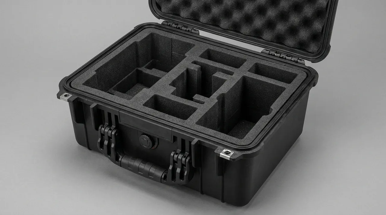
Two practical lessons. First, fewer materials are better. Multiple wrapping layers look cleaner but add fibre shedding, electrostatic attraction and particle generation at unpacking. Second, the liner should be removable as a whole for cleaning or replacement rather than permanently bonded into the case. A long-serving liner accumulates invisible contamination, and a removable design makes maintenance controllable. Liner machining tolerances — cavity depth, cavity width and multi-cavity consistency — directly determine locating performance; the general requirements are set out in custom foam insert selection and design guide.
9. Sealing, differential pressure and unpacking design
Sealing in an aseptic parts case serves two purposes: excluding external particles and moisture, and making the case interior a controllable environment. Within the IP rating system of IEC 60529 and GB/T 4208, aseptic service generally calls for IP65 or better, and IP67 where short-term immersion or heavy washdown is expected.
More important than the IP rating is differential pressure management. Air freight, high-altitude road transport and cross-climate sea freight all create a pressure differential across the case. Internal overpressure bulges the lid and loads the sealing lip unevenly; external overpressure makes the case hard to open and can even pull the lip into a deformed shape under vacuum. A pressure equalization valve is basic equipment for long-distance and air freight service. It allows slow air exchange while blocking liquid water and particles. See protective case pressure equalization valve for selection and mounting guidance.
The unpacking action itself belongs in the procedure:
- Open the case in the designated area — airlock, clean bench or under laminar flow — never in a non-clean area.
- First confirm exterior condition and seal status, and judge whether abnormal differential pressure, impact or moisture occurred.
- Peel from outside to inside, and handle outer and inner clean packaging separately.
- Remove grade A parts individually onto a clean surface and inspect sealing faces. Isolate any anomaly immediately rather than releasing it to assembly.
- Record unpacking time, personnel, part numbers and appearance condition.
10. Delivery configurations and transport validation
| Code | Delivery scenario | Case and liner | Sealing and pressure | Validation suggestion |
|---|---|---|---|---|
| --- | --- | --- | --- | --- |
| A-1 In-plant turnover | Between assembly and commissioning areas | Hard case with removable clean tray | IP54 or better | Liner location and handling convenience validation |
| A-2 Regional distribution | Inter-site transfer, third-party logistics | Medium case, clean liner, replaceable desiccant pocket | IP65 with equalization valve | Vibration and drop validation, dust ingress validation |
| A-3 Export and project delivery | Complete line export, on-site project delivery | Palletized case set, item-by-item numbering, document pocket | IP67 with equalization valve | Distribution cycle sequence test, humidity indicator record |
Validate in layers: liner location by vibration and drop, case sealing by dust and water testing, and the complete packed case by a distribution cycle sequence. For methodology see transport package basic testing and case design and executing an ISTA transport test program. Note that where an environmental test standard such as MIL-STD-810H is cited, it serves only as a source of methods; testing by its methods does not indicate military certification.
11. Acceptance and release process
Incoming acceptance for aseptic components should be stricter than for ordinary spares. Five fixed steps work well.
Step one, exterior package assessment. Inspect for deformation, damage and moisture, and check the equalization valve and gasket. If the lid needs obvious force to open and produces a hiss, the differential pressure in transit was significant and should be reviewed.
Step two, cleanliness assessment. On a clean bench, inspect the liner for particles, fibre and stains. If the liner is abnormal, stop unpacking, isolate first and assess.
Step three, component appearance and geometry check. Inspect grade A parts individually for sealing faces, conical faces, stem straightness and bore condition, and record the results. Grade B parts are checked by sampling ratio.
Step four, document verification. Cross-check part numbers, batch numbers, inspection reports and the packing list, and confirm traceability.
Step five, release decision. On pass, the part proceeds to cleaning or directly to assembly. On fail, isolate it and preserve the original packaging state for analysis.
The point of this process is to turn cleanliness and precision into a determinable result rather than a matter of operator experience. For companies running multiple sites, a unified acceptance sheet and sampling method are essential; custom case acceptance sampling provides a basis.
12. Customization and compliance documentation
Customization requests from aseptic filling equipment makers and packaging line users cluster around three items: clean liners designed to the component drawing, cases and liners that can pass through the sterilization process with the parts, and complete compliance and material documentation.
A workable sequence:
- Define the component list, the critical protected surfaces and the downstream cleanliness class.
- Confirm whether in-case sterilization is required, and which sterilant and temperature profile applies.
- Build and trial-fit the liner, validating handling convenience and locating reliability.
- Run complete-case transport and sealing validation and issue a validation report.
- Run a small batch in the field, collect feedback, fine-tune and freeze the drawing and acceptance criteria.
On food contact compliance, components that touch product and the packaging materials that contact them should be controlled against the GB 4806 series, with material grades stated, with regrind and unsuitable additives kept out of the compound, and material declarations plus test reports issued to the purchaser's requirement. Filling-valve and sterile-cavity geometry drives the liner and seal design produced by Kexin New Materials (Guangdong) Co., Ltd. For factory qualification, see how to choose a protective case OEM factory.
Frequently asked questions
Q: What cleanliness class should be specified for an aseptic filling valve spare parts case?
A: The right approach is to look first at the cleanliness class of the area the component will finally enter, then derive the packaging class. Do not default to the highest class. Over-specifying brings three costs: higher material cost, more complex unpacking in which the layer-by-layer peeling is itself a particle-generating action, and a tendency on the shop floor to skip procedures for convenience, which ultimately defeats the cleanliness control. In practice: for components used in a general filling area, a low-shedding wipeable liner is sufficient and the outer case only needs de-dusting before entering the hall; for a high cleanliness filling area, the liner should be clean grade and non-shedding, with the outer case stripped in an airlock and the inner case entering; for the aseptic core or inside an isolator, the liner should be sterilizable with the part and unpacking should happen on a clean bench or under laminar flow with item-by-item transfer. Write all three tiers into the annex so the supplier knows what to build. One further caution: the cleanliness class is not a case of higher being better. It must match the downstream process validation. If the component will be sterilized after assembly anyway, the packaging goal is to avoid degrading cleanliness and avoid introducing particles, not to attain a class for its own sake.
Q: What packing methods damage a filling valve stem or needle most often?
A: The two most common are lateral clamping and unsupported self-weight. Lateral clamping means pressing elastic material against the side of the stem to locate it. This is stable in a static condition, but under transport vibration the clamping force varies cyclically, so the stem sees repeated bending loads and can acquire a slight bend that is hard to see. After assembly the valve still actuates, but fill volume consistency drops, and the problem surfaces only when finished product weight sampling fails, which makes tracing extremely expensive. Unsupported self-weight means resting the stem on two end supports with the middle span free; under vibration the mid-span undergoes bending oscillation and straightness is lost the same way. The correct approach is axial support plus full-perimeter restraint: hold the stem along its length, for example in a U-shaped cradle, while limiting radial displacement without applying continuous side pressure, and add axial stops at both ends to prevent travel. If the part has conical or sealing faces, keep those clear of every hard component. It is worth making straightness inspection a fixed acceptance item and recording it item by item at packing time, so responsibility can be assigned quickly if a problem appears.
Q: What is the greatest risk to the sealing groove when a sterile chamber component is packed?
A: Three things: particles, fibre and adhesive residue. Particles such as metal swarf, dust or foam fragments sitting in the groove floor create a local gap when the O-ring is compressed, and the pressure hold or leak test after assembly fails outright. Worse, such defects are easily missed in visual inspection and only appear at test, consuming line commissioning time. Fibre from paper dust, textile fibres or non-woven shedding not only creates the same sealing gap but also tangles at the groove edge during cleaning, forming a retention point and a microbiological risk. Adhesive residue comes from protective films and labels: some films transfer adhesive after a temperature rise, the residue adheres to the groove sidewall, is difficult to remove completely by cleaning, and then adsorbs particles. The corresponding packing practice is to use no protective film inside the groove at all and instead protect the groove opening with a dimension-matched locating feature; choose non-shedding clean grade liner materials free of regrind; wipe and dry with clean cloth and a suitable solvent before packing, confirming no visible residue; and inspect grade A parts individually with magnification or strong light. If the component will subsequently pass through a sterilization tunnel, confirm that the locating material withstands those conditions without deformation or odour release.
Q: Why does chemical sterilant residue inside a spare parts case deserve special attention?
A: Because the residue keeps acting, and a closed case holds it right next to the component. Take strong oxidizers such as hydrogen peroxide and peracetic acid. If a component is packed before the post-sterilization rinse or volatilization is complete, the residue keeps working inside the closed environment. On one hand it can oxidize and degrade the liner, releasing small molecules that elastomer gaskets and metal surfaces then adsorb and later carry into the process. On the other hand the gasket itself ages faster under oxidizing conditions, so hardness and compression set performance degrade early and a leak appears shortly after installation. The correct logic is treatment and validation first, packing second, rather than packing now and rinsing before installation. Preconditions for packing should include a completed sterilization or cleaning cycle, a rinse and dry performed to validated parameters, and no visible residue or odour on the surface. Where the process allows, record the treatment batch and parameters on the packing record to create a traceable chain. If the component involves a pressurized vessel or media under specific transport controls, verify those compliance requirements separately rather than treating it as a routine spare.
Q: Why is a permanently bonded liner not recommended for aseptic components?
A: Because the liner is a consumable, not a permanent structural part. A non-removable liner — foamed in place or permanently bonded — has three problems. First, over time it accumulates invisible contamination including fine particles, grease and microbial metabolites, and that contamination cannot be fully removed by surface wiping, so the whole case must be scrapped. Second, the areas contacting the component gradually compress, locating force drops, the component gains slight freedom inside the case, and friction under vibration generates particles. Third, odour release increases as the material ages, and aseptic environments are highly odour sensitive. A removable design makes the liner a tray or module that can be lifted out as a unit with a replaceable desiccant pocket, so maintenance can clean, replace or upgrade the liner alone while the case body continues in service. For multi-cavity liners, modularize by component group so a damaged cavity means replacing only that module, which lowers maintenance cost. Removability also allows the liner to be cleaned and inspected separately before loading, and lets desiccant be changed without opening the loaded case. These details strongly affect actual compliance in high cleanliness environments. Define the liner as a replaceable item in the technical annex, with a stated replacement interval and judgement criteria.
Q: What items should a transport validation run for aseptic filling line spares cover?
A: Validate in layers so that a failure can be localized. The first layer validates liner location: load the actual components, run vibration and drop, and check for relative movement, compression marks on locating faces and abrasion on precision surfaces. The second layer validates case sealing: run dust and splash testing, or short-term immersion where required, checking for dust and water ingress, and verify that the pressure equalization valve responds correctly to pressure changes. The third layer validates the complete packed case over a distribution cycle: combine stacking, vibration, shock and temperature-humidity cycling to match the real logistics path, and check the case structure, latches, castors and handles under full load. The fourth layer is unpacking validation and handling convenience: have actual line operators open the case following the procedure and record the time taken and problems encountered. This layer is often skipped, yet it determines whether the shop floor will actually comply. Method sources that can be cited include the GB/T 4857 series for basic transport package testing, the ISTA transport test procedures, and the ASTM D4169 distribution cycle framework. Where MIL-STD-810H environmental methods are cited, state that they serve as a method basis only and do not imply military certification.
Q: Why is unpacking considered part of the protection design?
A: Because unpacking is the most contamination-intensive moment, and it usually happens where cleanliness requirements are highest. Picture opening a case under a laminar flow hood: lifting the lid, pulling out the liner, peeling the inner bag, removing parts one by one. That sequence generates particles through packaging friction, fibre shedding and re-suspension of electrostatically held dust — and those particles appear exactly where they must not. Unpacking design must therefore be planned together with packing design. Strip outer packaging in an airlock and let only the inner clean packaging enter the high cleanliness area. Open inner layers from outside to inside, with the contaminated face never crossing over the clean face. Remove waste packaging immediately instead of piling it inside the clean area. Inspect grade A parts individually on a clean surface before transfer. People and tools matter too: unpacking staff should be trained for the area, and tools such as scissors and knives must be controlled against dropping and against generating metal fragments. Writing this into an unpacking procedure with a checklist is more effective than simply raising the packaging class, because it addresses execution. The procedure should also include an exception path, such as how to isolate and report when particles are found in the liner.
Q: How should compliance and material documentation for aseptic spare parts cases be prepared?
A: Prepare it in three layers. The first is the material layer: state the grades of the liner, case body, gaskets and bag film, indicate whether regrind, plasticizers or other additives are present, confirm that materials contacting components are controlled against the relevant food contact material standard such as the GB 4806 series, and supply a material declaration. The second is the process layer: describe the cleaning method and cleaning agent, the drying method, the packing environment, whether it is a clean area or a clean bench, and the liner replacement interval and judgement criteria. The third is the validation layer: provide reports or data for liner location validation, case sealing validation and complete-case transport validation, together with the unpacking procedure and checklist. The three layers serve different purposes. The material layer supports audits and compliance, the process layer supports shop floor execution, and the validation layer supports purchase decisions and quality traceability. When submitting, organize by component family rather than by individual model to reduce document maintenance effort, and link documents to the case numbering system so each case has its own file. If the customer requires in-case sterilization, add a statement on the material's resistance under those sterilization conditions.
Conclusion and related reading
The core problem an aseptic filling spare parts case must solve can be stated in one sentence: the cleanliness and geometric precision of the component at arrival must match what it had when it was packed, and that must be demonstrable. Achieving it requires mapping cleanliness class to the downstream use area, using a removable clean grade liner to remove degrees of freedom, holding the internal environment with sealing and differential pressure control, turning packing and unpacking into documented procedures, and replacing rules of thumb with layered validation.
Aseptic-filling case production is coordinated by Kexin New Materials (Guangdong) Co., Ltd., which serves wholesale, distribution and OEM/ODM channels worldwide, with filling-valve and sterile-cavity liners plus documents provided on request.
Related reading