

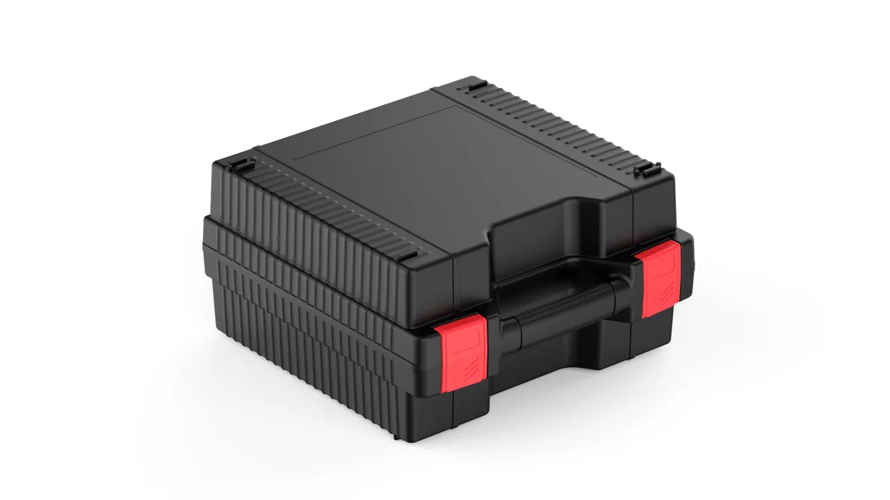
On a thermoforming line the machine does not decide product quality — the forming mold does. That mold is an aluminium cavity block, a dense array of vacuum micro-holes drilled through the cavity floor and sidewalls, cooling channels bored through the body, and a set of matching parts: the vacuum-chamber cover, the clamp frame and the pressure ring. Such a mold may weigh only a few tens of kilograms, yet its entire value sits on a few square decimetres of curved surface. Scratch that face, drag a burr across it, or let aluminium chips and release-agent residue plug the micro-holes, and the validated process window collapses: wall thickness drifts, surface gloss fails, and de-molding rhythm changes. Sustained road vibration, lateral impact during handling, and the humid air inside a trailer during the rainy season attack exactly those three weak points.
JUNZHIJIA builds its protection principle for thermoforming molds on three commitments: hold the cavity face with a soft, form-fitting liner, hold the pairing relationships with numbered compartments, and hold the cooling-channel bore with drain-and-dry plus humidity control. A protective case is not a box that contains a mold; it is a fixture that keeps a forming mold on the same validated process datum for the entire journey. This article follows four threads — cavity face, vacuum holes, water channels and parting surfaces — and sets out the materials, structures, parameters and acceptance criteria that mold shops, plastics processors and equipment integrators can quote directly in a technical agreement.
Table of Contents
- Soft Failure Modes on Thermoformed Aluminium Cavity Faces: Where Scuffing Starts
- Clogged Vacuum Micro-Holes: The Invisible Fault That Skews Wall Thickness
- Residual Cooling Water: The Hidden Electrochemical Corrosion Path in Transit
- Parting-Line and Clamp-Frame Flatness: The First Suspect for Vacuum Leakage
- Numbered Compartments for Multi-Cavity Molds, Inserts and Cores
- Non-Marring Liner Selection: IXPE, EVA and Flocked Composite Compared
- Drain-and-Dry Procedure: Air Purging, Vacuum Drying and Desiccant Dosage
- Mould Mass Distribution and Pallet Load: From Single Unit to Full Load
- Anti-Distortion Tooling for Vacuum-Chamber Covers and Clamp Frames
- Enclosure Sealing Class, Pressure-Equalisation Valve and Humidity Logging
- Road Vibration Spectrum and Damping Evaluation for Forming Molds
- Pre-Shipment Acceptance Criteria and Documentation Pack
- Frequently Asked Questions FAQ
- Conclusion and Related Reading
Soft Failure Modes on Thermoformed Aluminium Cavity Faces: Where Scuffing Starts
Thermoforming cavity faces are usually machined from 6061, 7075 or 5083 aluminium plate and then polished to Ra 0.4–0.8 μm; high-gloss tooling goes further, to a mirror finish. Aluminium sits at Mohs 2–3, far softer than steel, so damage rarely arrives as a single heavy blow. It arrives as relative slip. When the mold body is not fully constrained inside the case, road vibration produces millimetre-scale reciprocating motion; the block presses its own mass onto grit, chips or a hard liner edge and grinds the polished face into a patch of scuffing. The second mechanism is point-contact indentation: support blocks, bolt heads and lifting eyes concentrate stress onto the cavity face under 1–2 g vertical acceleration, leaving depressions that cannot be polished out without losing the form.
Two questions quickly test whether a transit scheme is sound. First, is the mold body constrained in all six degrees of freedom? Second, are the contact surfaces non-shedding, soft and softer than aluminium? If either answer is no, the cavity face is exposed. The standard remedy places 25–35 Shore 00 IXPE or EVA pads under the base and along the sides, and those pads touch only non-forming datum surfaces, process bosses or the mold base rail — never the cavity face or the parting lip.
| Cavity-face failure | Trigger | Consequence | Structural countermeasure |
|---|---|---|---|
| --- | --- | --- | --- |
| Long scuff bands | Body slip plus hard particles | Hazy parts, re-polishing required | Full-contact soft pads, clean interior |
| Point indentations | Excess local contact stress | Thin spots and bright marks | Larger contact area, distributed supports |
| Chipped parting lip | Lateral impact on the lip | Vacuum leak, costly repair | Lip guard strip, displacement stops |
| Chemical staining | Sweat or oil left in place | Dull polish, erratic release | VCI film, oil-free handling gloves |
| Anodised layer cut through | Hard-object abrasion | Local loss of corrosion resistance | Interleaf non-woven, individual soft bags |
The table matters because it converts a vague fear of scratching into measurable contact stress and relative displacement. Select a contact material, a contact area and a restraint method for each row, and the protective scheme becomes an engineering input rather than a matter of opinion.
Clogged Vacuum Micro-Holes: The Invisible Fault That Skews Wall Thickness
Forming molds typically carry vacuum holes of φ0.5–1.5 mm on a 15–40 mm pitch, chamfered or counterbored on the cavity side. Once a hole is blocked by aluminium chips, dried release-agent residue, paper fibre or foam fragments, the local extraction rate drops, the sheet lags behind the mold surface, and the part develops thick patches, under-formed corners or tears. Blockage usually happens during packing and loading: the mold is set straight on the trailer floor and floor grit is pressed into the hole mouths, or loose foam filler sheds fragments that lodge in the bores, or paper padding absorbs moisture and pastes over the openings.
The interior of a protective case must therefore stay a debris-free environment. Use closed-cell IXPE liners, avoid bare expanded polystyrene and loose foam beads, and cover the cavity face with a non-woven sheet or PE electrostatic film laid flat — folds press into hole mouths. When a mold comes directly off the line, blow it through first with dry compressed air, working against the normal flow direction, then remove the release-agent film with a soft brush and neutral cleaner, and let it dry completely before packing.
For multi-cavity molds with more than 500 holes, record the protection-film type and the removal sequence in the packing documents, and include a spare film roll inside the case. A common shop-floor error is to fit the film without labelling it; the fitter then pulls the film free at the machine and drags dust into the holes on the way out. Leave a 20–30 mm return at the film edge, lift the return first, and peel parallel to the cavity face instead of dragging across it.
Residual Cooling Water: The Hidden Electrochemical Corrosion Path in Transit
Cooling channels are bored through the mold body and finished with stainless plugs or brass fittings. When a mold is idled, stored or shipped long distance, the water left inside forms an oxygen-concentration cell inside a closed cavity: the aluminium body acts as the anode and dissolves preferentially, especially at fitting threads, channel bends and stagnant sections. Within months, white flocculent corrosion product and visible pitting appear. The damage is invisible at unpacking and only surfaces on the machine, as localised mold-temperature drift and regular colour banding on the part. Repair then means stripping the mold base, re-sealing and pressure testing — an expense far larger than the packing budget.
The core of water-circuit protection is drain first, dry second, seal last. A workable sequence: purge with dry compressed air in the normal flow direction for at least 30 s, then reverse-flow purge for the same period; follow with clean dry air at 0.05–0.08 MPa for 2 h, or vacuum drying at 40–50 °C and −80 kPa for 4 h; finally fit dust plugs to the inlet and outlet, each labelled "drained" with the date. If the mold ships during a humid season, inject a small volume of volatile corrosion inhibitor into the channels, close both ends, and flush with clean water on arrival before running.
Humidity inside the case matters just as much. Fit silica gel or molecular sieve desiccant at 20–30 g per 10 L of net case volume, and place a humidity indicator card on the inside of the lid. Set the reading threshold at 40 %RH: above that value the desiccant is close to exhaustion, so replace it or apply corrosion protection immediately after opening.
Parting-Line and Clamp-Frame Flatness: The First Suspect for Vacuum Leakage
The parting line and the clamp-frame lip determine how well a mold holds vacuum after closing. Parting surfaces are normally held to 0.05 mm per 300 mm flatness, and the clamp lip is more sensitive still because sheet clamping force acts directly on it. Two transport failures dominate: local edge rolling from lateral impact and global twist from poor support. When the body is carried on two end supports with the middle unsupported, self-weight and vibration combine into elastic deflection, and repeated cycles convert it into permanent bow.
Three structural rules follow. First, support points must sit on the mold base or backing plate, never on the parting surface. Second, the number of support points follows body length — normally one group every 400–500 mm — with load variation between points held within ±15 %. Third, fit lateral stops that leave a 3–5 mm gap filled with soft padding, so the mold can move slightly under emergency braking while the padding absorbs impact energy. For molds with corner guide pillars and bushings, wrap the pillars in soft sleeves and carry the mold base on locating blocks so the pillars never see bending load.
Before loading, check the parting surface with a straight edge or electronic level and ship the original readings with the case. That baseline decides claims and acceptance at destination: without it, no one can prove the distortion happened in transit.
Numbered Compartments for Multi-Cavity Molds, Inserts and Cores
A multi-cavity thermoforming mold is a kit: mold base, several independent cavity inserts, cores, cutting punches and pressure bars. The parts look similar and measure similarly, so mixed packing forces the fitters to compare them one by one on site — slow, and prone to mismatching. Numbered compartments exist to fix an intangible piece of information, the pairing relationship, into the physical packing structure.
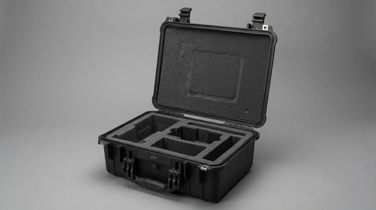
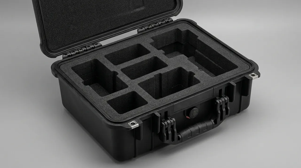
Use a one-part-one-pocket, one-pocket-one-number rule. Cut the liner to the part outline by CNC, laser-etch or screen-print the position number beside each pocket, and make that number match the position callout on the mold assembly drawing. Paste an enlarged layout drawing on the inside of the lid showing number, part name and quantity. For thin-walled fragile inserts, wrap each in EVA before it goes into its pocket and apply the same number label to the wrap. For cutting punches, fit PE edge guards with a thin film of anti-rust grease on the inner face.
Counting needs design as well. Ship a packing list with six columns — pocket number, part name, drawing number, quantity, unit weight, protection applied — and require the receiving team to open in pocket-number order and tick each line. Experience shows that a pocket-numbered list cuts site counting time by more than half and sharply reduces high-cost errors such as a missing insert discovered only at assembly. For a mold entering production for the first time, complete a first-article confirmation before packing, following the sequence in Protective Case Mold Trial Run Guide: First-Article Inspection and Parameter Confirmation.
| Part category | Typical feature | Main risk | Pocket design |
|---|---|---|---|
| --- | --- | --- | --- |
| Cavity insert | Thin wall, curved form | Impact distortion, face scuffing | Dedicated pocket plus EVA wrap |
| Core / male form | Slender, sharp nose | Nose chipping | End cap plus axial location |
| Cutting punch | Sharp cutting edge | Edge chipping, hand injury | PE guard, isolated compartment |
| Pressure bar | Long and flexible | Bowing, uneven clamping | Full-length cradle, multi-point support |
| Guide pillar / bushing | Precision fit | Surface galling, rust | Soft sleeve plus VCI film |
| Fastener kit | Many small pieces | Loss, mixing | Divided tray plus label |
Non-Marring Liner Selection: IXPE, EVA and Flocked Composite Compared
Liner selection for forming molds is not a question of softness alone; hardness, resilience, closed-cell structure and residue behaviour all count. EPE is cheap and resilient but has low surface friction, creeps under sustained load, and sheds particles when it breaks — particles that find their way into vacuum holes. EVA spans a wide hardness range, can be CNC-milled into a form-fitting cavity and, being closed-cell, does not shed; it is the workhorse for cavity-type parts. IXPE has a higher cross-link density, a finer surface and better puncture and ageing resistance, making it a good facing layer. A flocked composite — non-woven bonded to PE or IXPE — has moderate friction and a soft hand, and suits direct contact with polished cavity faces.
A three-layer build is common in practice: a load-bearing layer of 30–45 kg/m³ EPE or high-density EVA for cushioning, a form layer of 25–35 Shore 00 IXPE or EVA milled to the outline, and a contact layer of non-woven or flock to isolate the cavity face. Bond the layers with hot-melt film rather than solvent adhesive; residual solvent reacts with aluminium and leaves stains. For density, resilience and ageing differences across these foam families, see Protective Case Interior Foam Types: EPE, EVA, IXPE and PU Compared, and for single-shot forming of a curved liner see EVA Thermoformed Liner Process: From Sheet to Form-Fitting Cavity.
One frequently ignored parameter is compression set. Under long-term stacking, a liner whose compression set exceeds 10 % relaxes its pockets; when the case is opened the mold is loose, and it travels unconstrained on the return leg. Run a 72 h test at 40 % compression and 23 °C on new liner material, and reject anything with less than 90 % recovery for reusable transit packaging.
Drain-and-Dry Procedure: Air Purging, Vacuum Drying and Desiccant Dosage
Drain-and-dry is the step most often skipped and the one that hides the most risk. The parameters below can go straight into a work instruction.
Step one: after isolating water and power, disconnect the quick couplings and purge with 0.5–0.6 MPa dry compressed air in the normal direction for at least 60 s, watching until no droplets or mist leave the outlet. Step two: purge in reverse for at least 60 s, concentrating on bends and stagnant sections. Step three: apply −70 to −80 kPa vacuum at 40–50 °C for 4 h, or use 60 °C hot air for 2 h — either method, but standardise on one within a plant. Step four: fit dust plugs immediately and record the completion time. Step five: before packing, spray a thin volatile corrosion inhibitor on the cavity face and parting surfaces, targeting a 1–3 μm film; heavier films attract dust.
Size the desiccant against net case volume: silica gel at 2–3 g/L, molecular sieve at 1.5–2 g/L; calcium-chloride blends are best reserved for cases holding non-metallic parts. Suspend or fix the desiccant to the inside of the lid so it never touches the mold, and fit a reversible indicator card. For shipments longer than 30 days or routing through humid regions, add a Bluetooth temperature and humidity logger with a 10-minute sampling interval as objective evidence for acceptance on arrival.
Mould Mass Distribution and Pallet Load: From Single Unit to Full Load
A forming mold is not heavy on its own, but a shipping unit usually includes the base, cover, clamp frame, spares and fixtures, and can reach 300–600 kg. The pallet and case floor must be checked against the worst case: a dynamic load factor of 1.5–2.0 for road transport, stacking height taken from the actual storage plan, and the bottom case carrying the full weight of everything above it.
Work through the checks in order. Calculate total unit weight, including mold, liner, case and accessories. Multiply by stacking layers for the bottom-case load. Verify the span of the case floor ribs and the pallet cross-members. Finally check forklift entry positions and the centre-of-gravity envelope. Keep the centre of gravity low and central; if it deviates by more than 10 % of the case short side, add lifting-point and centre-of-gravity labels outside and state "no single-side lifting" in the documents. Remove lifting eyes from the mold and pack them separately, so they neither deform nor scratch the case wall in transit.
| Condition | Load factor | Checked item | Typical problem |
|---|---|---|---|
| --- | --- | --- | --- |
| Road, full truckload | 1.5–2.0 | Case floor, stacking layers | Bottom case creeps over time |
| Rail / intermodal | 2.0–2.5 | Lateral stops, straps | Side slip, strap slackening |
| Manual handling | 1.2 | Handles, hinges | Handle pull-out, hinge distortion |
| Six-month stacking | Static 1.0 | Walls and ribs | Lid hard to open after compression |
| Forklift handling | 3.0 local impact | Pallet feet | Foot cracking |
Anti-Distortion Tooling for Vacuum-Chamber Covers and Clamp Frames
Vacuum-chamber covers and clamp frames are classic large-and-thin structures: large area, limited plate thickness, stiffness supplied by folded edges and ribs. Two transport conditions cause the most trouble — a load pressing on the middle and bowing the cover, or two-point support twisting it overall. The first degrades sealing-face contact; the second changes how the frame locates against the mold.
Treat the cover and the frame as independent items. Support them on a shaped wooden or high-density EVA cradle placed under the ribs, so load travels through the ribs rather than through the flat panel. Cover the four corner sealing faces with soft strip. For covers over 1 m², use a full-base cradle to spread the load evenly. If the cover carries a window, a transparent panel or acrylic parts, that area must see no point load at all, and the window should be removed and packed in its own case when necessary.
Fit a PE protection film between the frame and the cover mating faces to prevent coating or anodised-layer wear from relative slip. On anodised covers, keep untreated steel parts and sulphur-bearing rubber away from the surface; in warm humid conditions such rubber releases sulphides that discolour aluminium.
Enclosure Sealing Class, Pressure-Equalisation Valve and Humidity Logging
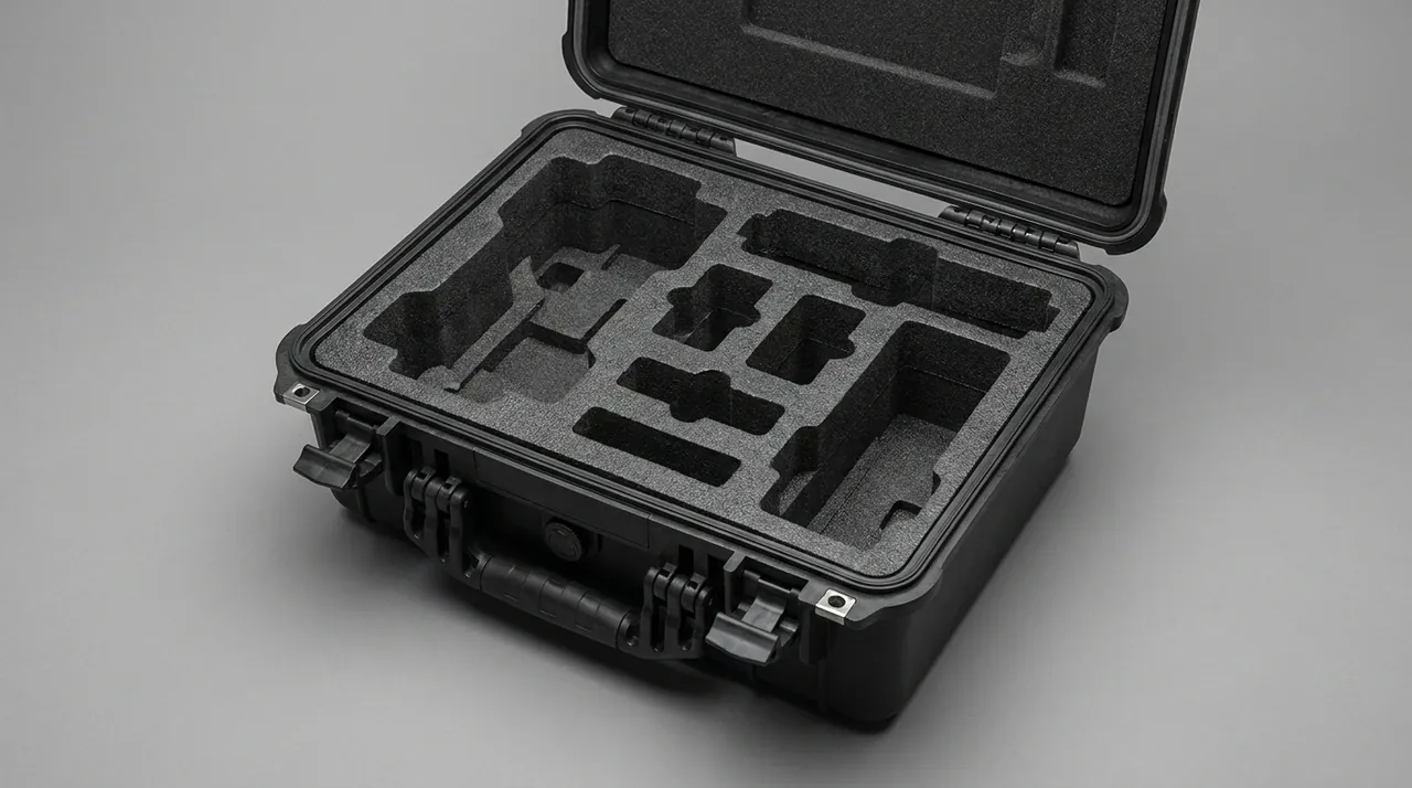
A thermoforming mold is not precision electronics, but an aluminium cavity face is highly humidity-sensitive, so the case needs a basic dust and water barrier. The usual benchmarks are IP65 (dust-tight, water-jet protected) and IP67 (short-term immersion), tested to IEC 60529 or GB/T 4208. For domestic road transport and ordinary warehousing, IP65 is sufficient; for sea freight, open-air staging or transfer through rainy regions, design to IP67, where the decisive factors are gasket compression and the joint overlap.
The gasket is the part that ages first. Common materials are EPDM, silicone and expanded polyurethane: EPDM offers good weathering and ozone resistance at moderate cost; silicone recovers better and tolerates higher temperatures at a higher price; expanded polyurethane seals well when new but takes a larger compression set. Target 25–35 % gasket compression — below 20 % invites water ingress, above 40 % makes the lid hard to close and overloads the latches. Inspect annually, and replace the whole run if it has hardened, cracked, flattened permanently or debonded. Valve membrane grades, thread sizes and installation torque follow the selection table in Pressure-Equalisation Valves for Protective Cases: Working Principle, Selection and Installation.
The pressure-equalisation valve is often omitted and is genuinely important. In a sealed case, a move from low to high altitude or a day-night temperature swing can create a pressure differential of several kPa, enough to lift the gasket or flex the wall and break the seal. A valve with a waterproof breathable membrane passes air while blocking liquid water and dust. Mount it high on a non-load-bearing wall, clear of stacking pressure zones and direct spray. For shipments needing traceability, add an internal temperature and humidity logger and ship the pre-dispatch record as an attachment.
Road Vibration Spectrum and Damping Evaluation for Forming Molds
Road transport vibration concentrates between 3 and 30 Hz, with the strongest energy at 5–15 Hz; rail freight carries more high-frequency energy; sea freight is dominated by low-frequency roll and whole-case tilt. A forming mold is stiff, with natural frequencies well away from the dominant excitation, so risk concentrates in accessories and inserts. Slender pressure bars, thin-walled inserts, guide pillars and anything not fully tightened can resonate as secondary masses against the case, and prolonged vibration loosens fasteners and frets contact surfaces.
Evaluation can be refreshingly simple. Assemble the liner and mold in their shipping state, run a 30-minute sweep on a shaker table (3–100 Hz, acceleration stepped up to 1.0 g), then inspect fastener torque retention, bright marks on contact faces and pocket indentation. Without a shaker, run a 50 km comparative road test under identical conditions and compare two liner designs. Either way the acceptance figures should be numeric: torque decay no more than 10 % of the initial value, no new bright marks, and pocket dimension change no more than 0.3 mm.
The three levers for vibration resistance, in order of effectiveness, are lowering the centre of gravity, increasing contact area, and eliminating clearance. Where clearance must remain, fill it with compressible padding whose restoring force exceeds the transport inertial force — especially important at the ends of slender parts.
Pre-Shipment Acceptance Criteria and Documentation Pack
Run pre-shipment acceptance as look, measure, test, record, so problems do not leave the gate.
Look: no new scratches or bright marks on the cavity face, no blocked vacuum-hole mouths, no rolled parting lip, all water-channel plugs fitted. Measure: sample parting-surface flatness with a straight edge or electronic level, check liner-to-mold gaps with a feeler gauge, verify critical fastener torque with a torque wrench. Test: close the lid and check latch travel and gasket compression, and where warranted run a simple airtightness test at 5 kPa held for 60 s. Record: enter every value in the dispatch inspection record and ship the packing list, layout drawing, initial humidity-card reading and corrosion-treatment log with the case.
The documentation pack should contain the pocket-numbered packing list, the transport layout drawing, the drain-and-dry and corrosion-treatment record, desiccant type and quantity, humidity-card reading instructions, unpacking and re-assembly sequence, and a summary of warranty and claim terms. For export projects, add a declaration of conformity and a transport test report, for example to ISTA or ASTM D4169.
For forming molds, a liner built from 3D data, a shaped cradle milled in the same operation and an integrated documentation pack remove most of the guesswork from transit. Writing the parameters into the technical agreement at quotation stage is what turns a case into a protective system.
Frequently Asked Questions FAQ
Q: The cavity face has already been mirror-polished. Which liner will not leave marks in transit?
A: The only acceptable contact layer for a mirror cavity face below Ra 0.2 μm is a non-shedding non-woven or flocked PE composite, 1–2 mm thick, with a flat PE electrostatic film laid between it and the cavity face. Never let EPE bead foam touch the polished surface directly: under pressure it releases fine particles that press into the surface and form micro-scratches that only a full re-polish can remove. For the form layer, mill 25 Shore 00 IXPE or low-hardness EVA to the cavity contour and hold the mating clearance within 0.5 mm, then check that the liner sits flat rather than folded, because a crease concentrates stress on a small area of the polished face and can leave a permanent line. Handling discipline matters as much as material choice. Bare hands and worn gloves carrying grit are prohibited; use powder-free nitrile gloves with disposable PE finger cots whenever the mold is open. Blow the cavity clean with dry compressed air and lint-free wipes before fitting the film, and record the film type and removal sequence in the case documents so nobody drags dust across the face during unpacking.
Q: The cooling channels were already purged with compressed air, so why is there rust after unpacking?
A: Compressed air removes bulk liquid water but not the wall film or the droplets trapped in bends and stagnant sections. That residual water forms an oxygen-concentration cell inside the closed channel and pits the aluminium body within weeks, most often at fitting threads where two different metals meet. The correct sequence adds a drying step after purging: either 60 °C hot air for 2 h, or vacuum at −70 to −80 kPa with 40–50 °C heating for 4 h. Verify dryness instead of assuming it — hold a cold mirror or a sheet of white paper at the outlet and watch for condensation, or check the outlet dew point with a portable hygrometer. Check also that plugs are fitted after drying rather than before, because closing the channel first traps moisture inside and makes the outcome worse. Where the shipment will last more than two months, inject a volatile corrosion inhibitor into the channels and note in the documents that the circuit must be flushed before service. Record the drying method, temperature, duration and completion time, since corrosion claims are settled by that log.
Q: There are hundreds of vacuum micro-holes. Do we need to check every one before dispatch?
A: Individual gauging of every hole is unnecessary, but sampling plus a general blow-through is essential. Divide the cavity into zones and sample ten holes per hundred, touching each with a φ0.4 mm soft copper wire or a purpose-made reamer while blowing compressed air in reverse, watching for smooth flow and any particle discharge. If a sample fails, expand to full inspection across that zone before the mold is packed. Raking side light across the face reveals paper fibre, adhesive residue and aluminium chips around the mouths; a strong torch held almost parallel to the surface is usually enough for the job, and a low-power magnifier helps on small pitches. If the mold comes straight from the line, remove release-agent film with a neutral cleaner, rinse, and dry it completely before packing. Log the sampling record in the dispatch inspection record together with the zone map, the number of holes checked and the acceptance result, so responsibility can be traced if a blockage appears at destination. Record the probe diameter used for the check, because an oversized wire can deform a chamfered mouth and create a new burr, harder to remove than the blockage it was meant to clear.
Q: How should inserts and cores be numbered so a multi-cavity mold can be counted quickly on site?
A: Numbering must match the position callouts on the mold assembly drawing exactly, using a one-part-one-pocket, one-pocket-one-number rule. Cut the liner to each part outline by CNC and laser-etch or screen-print the position number beside its pocket. Paste an enlarged layout drawing inside the lid, listing position number, part name and quantity, so the fitter never has to guess which insert belongs where. For fragile parts packed in individual wraps, apply the same number to the outside of the wrap. Ship a packing list in six columns: pocket number, part name, drawing number, quantity, unit weight and protection applied. Require the receiving team to open in pocket order and tick each line rather than counting loosely. For export molds, print position numbers in both Chinese and English and add columns for material and surface treatment, which simplifies both customs review and incoming inspection. Where two inserts are mirror images of each other, add a left-right marker to the pocket number to prevent a reversed fit at assembly. Keep a laminated copy of the packing list in the lid pocket too, because a loose paper sheet inside a sealed case absorbs moisture and can shed fibre onto the cavity face.
Q: Is a pressure-equalisation valve really necessary, or does it just create a water-entry point?
A: It is necessary, but only if you select a version with a waterproof breathable membrane. A fully sealed case that experiences temperature swings and altitude changes develops an internal-to-external differential of several kPa, enough to lift a gasket or flex the wall and destroy the seal. A qualified valve uses an expanded polytetrafluoroethylene membrane whose pores are far smaller than a water droplet, so it equalises pressure while blocking liquid water and dust. Mount it high on a non-load-bearing wall, away from stacking pressure zones, direct spray and any recess where water can pool, and fit it on a threaded boss with an O-ring under controlled torque. Never drill a plain hole as a substitute, because that admits both water and grit and defeats the gasket entirely. After installation, run a simple airtightness check at 5 kPa for 60 s; a pressure drop within 10 % is acceptable. Inspect the membrane annually, and replace the valve if it has been submerged or shows any tear. Where the case will travel by air, check the valve rating against the cabin-to-hold pressure swing before departure, because the differential is larger than most ground shipments will ever produce.
Q: The mold is not heavy, so why bother with pallet load and stacking calculations?
A: Because the shipping unit is far heavier than the mold. A unit containing the mold base, cover, clamp frame, spares and fixtures commonly reaches 300–600 kg, and stacking three high puts 600–1200 kg of static load on the bottom case. Add a road transport dynamic factor of 1.5–2.0 and the real loading becomes substantial; rail and intermodal legs push that factor to 2.0–2.5, and forklift contact adds a local impact far higher again. Long-term stacking also induces compression set in the liner, so pockets relax and the mold travels unconstrained on the return leg. The check sequence is total unit weight, stacking layers, case floor rib span, pallet cross-member span, forklift entry position and centre-of-gravity envelope. Keep the centre of gravity low and central, and label the case when it deviates by more than 10 % of the short side. Skip any one of these steps and the problem usually appears only when the container is being loaded. Where one pallet carries several molds as a combined unit, treat the assembly as a single load case and re-check the combined centre of gravity rather than each mold on its own.
Q: Which tools should be used to verify parting-surface flatness, and how detailed should the record be?
A: Most plants can sample adequately with a straight edge and feeler gauge; tighter requirements call for an electronic level or a laser flatness measuring instrument. The record should include the measurement date and ambient temperature, numbered measurement locations — eight points around the perimeter and along the diagonals works well — the reading at each point, the maximum deviation and the acceptance conclusion. Measure with the mold resting on its shipping supports rather than on the shop floor, because the support condition changes the reading and can mask a twist that will appear inside the case. Ship the original record with the case and keep an electronic copy. In a claim at destination, no baseline measured before loading means no way to prove the distortion occurred in transit, so the record protects both the mold shop and the carrier. If the mold has guide pillars and bushings, record pillar perpendicularity and bushing bore as well, because lateral impact usually shows up there first. Keep the gauge and the record sheet stored together inside the case, so the outbound and inbound measurements are taken with the same instrument and can be compared directly.
Q: How do we assess liner degradation after repeated transit cycles?
A: The two governing indicators are compression set and recovery rate. Sample the liner material and run a 72 h test at 40 % compression and 23 °C; anything below 90 % recovery is unsuitable for reusable transit packaging. In service, re-measure pocket dimensions every twenty shipments and replace the liner once a dimension has shifted by more than 0.3 mm. Watch the surface as well: powdering on IXPE, visible flattening on EVA, and fibre shedding from a flock layer all indicate that the material has entered its degradation phase. If one case ships more than ten times a year, keep a liner life log keyed to shipment count rather than calendar age, because cycle count tracks real wear far more closely than elapsed time does.
Conclusion and Related Reading
For forming molds, arrival condition decides whether a line restarts on schedule. JUNZHIJIA builds form-fitting liners, numbered compartments, drain-and-dry records and OEM/ODM tooling for mold makers.
Related Reading