

A power transformer built at one works and commissioned in another travels a thousand kilometres or more before it reaches its foundation. The route is rarely a single leg: it moves by road on a low-bed trailer, crosses a rail wagon as deck cargo, rides on a ship hatch cover, and is handled by a crane at every intermediate transfer. The steel tank survives that itinerary reasonably well. What does not survive it are the parts that are long, brittle, thin-walled and not allowed to be loaded arbitrarily: the porcelain or epoxy skirts of a bushing, the sheet-metal fins and welded oil chambers of a radiator, the valves and nameplates on the tank roof, and small fragile accessories such as the Buchholz relay and the breather. The saying that circulates among substation crews is blunt: a transformer does not mind being dropped, it minds having its porcelain skirts knocked off.
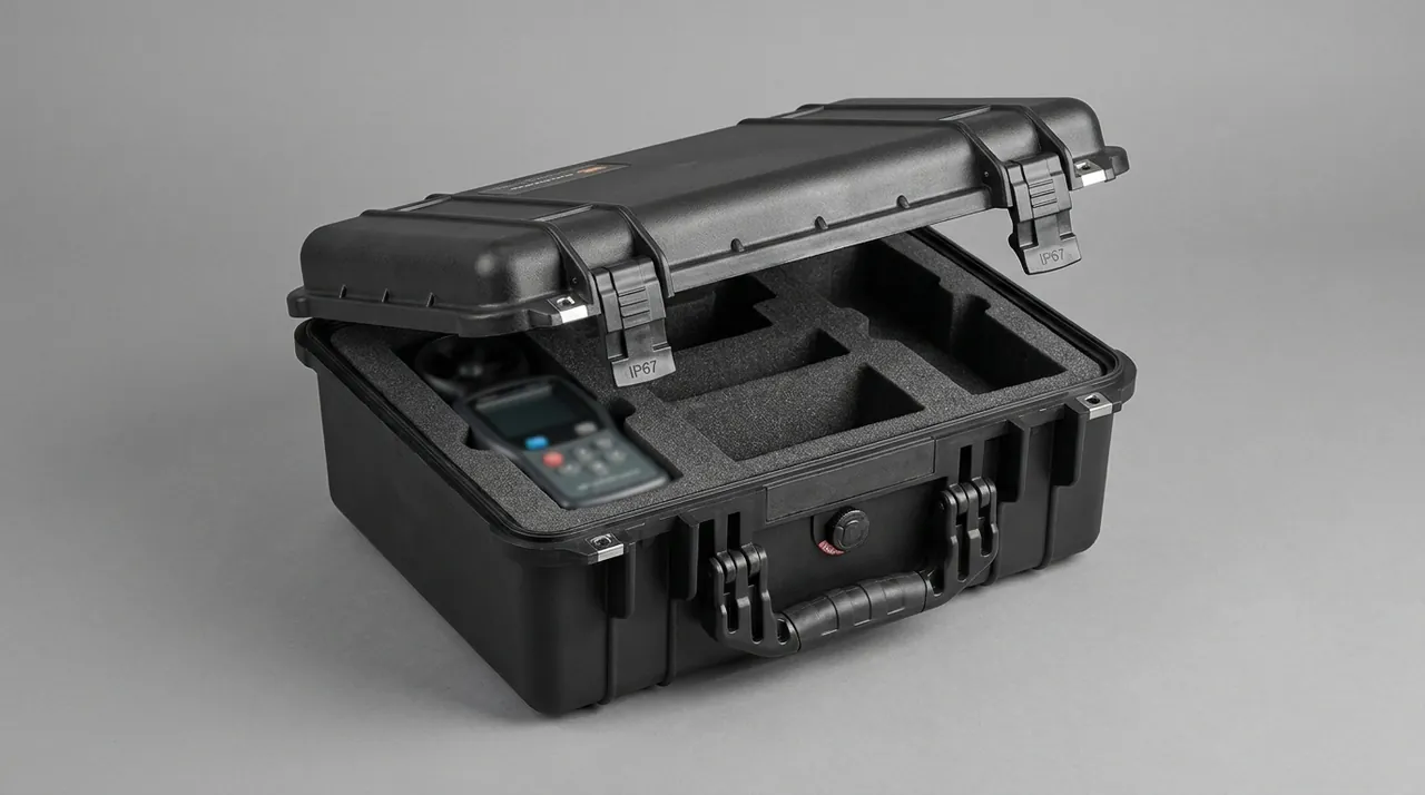
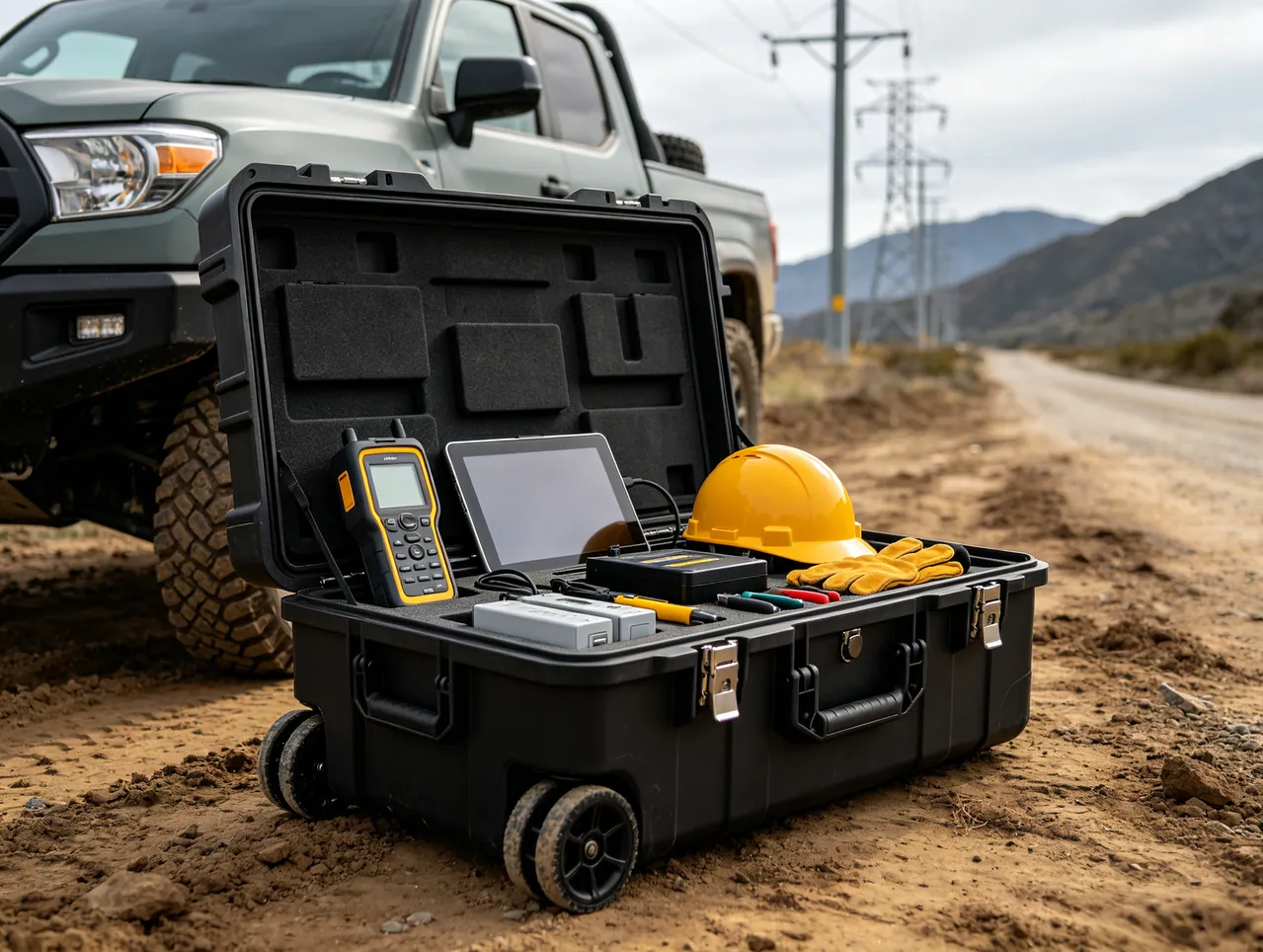
A transport case should be designed on one premise: the shell is the load-bearing element, and the liner is the protection element. JUNZHIJIA approaches transformer component packing by treating the bushing, the radiator bank and the tank accessories as independent load paths, and by using removable compartmentalised foam to rewrite the impact path from a rigid collision into a progressive crush, so that skirt edge stress, fin bending strain and weld seam preload all stay inside their allowable values across the declared transport envelope. Tank-mounted parts are covered separately in power transformer component cases. The rules below apply to the individual pieces that arrive on site as separate crates.
Table of Contents
- Porcelain Skirt Chipping on 110 kV Bushings and Cavity Envelope Clearance
- Epoxy Composite and Porcelain Bushings: Two Different Damage Mechanisms
- Bushing Seal Elastomer Compression Set and Preload Preservation in Transit
- Radiator Fin Bending Mechanics: Whole-Group Bow and Local Buckling
- Oil Chamber Weld Micro-Crack Growth and Transit Risk Isolation
- Upper and Lower Radiator Flange Flatness Through Stack Load
- Tank Lifting Lug Load Paths and Sling Selection for Overland Moves
- Accessory Sub-Compartments for Buchholz Relay, Breather, Valves and Nameplate
- Freeze-Thaw Cycling and Diurnal Condensation on Flatcar and Hatch Deck Routes
- Coastal Salt Spray on Radiator Fins, Tank Steel and Threaded Fasteners
- Whole-Tank Lift Versus Component-Level Packing: A Trade-Off Audit
- Three-Density Foam Gradients and Removable Sub-Compartment Construction
- Goods-In Acceptance: Oil Level, Weld Leakage and Insulator Integrity
- Frequently Asked Questions FAQ
- Conclusion and Related Reading
Porcelain Skirt Chipping on 110 kV Bushings and Cavity Envelope Clearance
The first damage mode for a porcelain bushing in transit is not puncture or flashover. It is a chip off the edge of a skirt. On units of 110 kV and above, the wall at the smallest skirt diameter is frequently only 8 to 15 mm thick, and the skirt end face is a free boundary, so the bending stress concentration factor at that edge routinely exceeds three. When the contents displace inside the case a wedge action develops: the foam compresses and pushes the bushing outward, a skirt tip bears on the arris of a foam bore, the contact patch collapses to a few square millimetres, and the peak pressure passes the compressive strength of the porcelain almost immediately. The visible result is a chip the size of a grain of rice, easily missed under inspection lighting, which resurfaces as a breakdown during a later withstand or lightning impulse test.
Envelope clearance therefore rests on a single rule: no hard edge is permitted anywhere. The bore of every compartment that receives a bushing is wrapped continuously, openings are chamfered so that any arris the skirt can reach has a radius of the same order as the foam thickness, and no metal strap, batten, label plate or stiffener may lie on the path a skirt sweeps through. Clearance between the bushing wall and the compartment wall is set so displacement has somewhere to go before it is arrested, and internal stiffening is positioned outside the swing envelope.
| Damage mode | Trigger | Stress manifestation | Packing response |
|---|---|---|---|
| --- | --- | --- | --- |
| Skirt edge chip | Displacement against a hard arris | Edge bending concentration | Continuous wrap, chamfered bore, no hard contact points |
| Skirt root longitudinal split | Axial shock superposition | Tensile stress above allowable | Removable annular collar beneath the root |
| Porcelain column transverse crack | Lateral drop impact | Bending stress | Upper and lower supports, limited unsupported span |
| Bushing-to-flange bond separation | Adhesive interface peel | Shear and peel | Separate annular support at the flange face |
The skirt root deserves separate attention, because the transition radius between skirt and column sets the stress concentration factor, and in transit that transition often sits directly on the case floor or against a compartment panel. Common practice places a removable annular locating collar beneath the root, holding 2 to 3 mm of clearance. The collar limits lateral excursion without carrying load, which prevents the repeated swinging that starts fatigue at the root while introducing no new contact stress.
Epoxy Composite and Porcelain Bushings: Two Different Damage Mechanisms
Composite epoxy bushings, the dry insulation type, are increasingly common above 220 kV, and their protection logic is close to the reverse of that for porcelain. Porcelain is a brittle ceramic: once the input energy exceeds the allowable level it fractures, an energy-controlled failure with no warning. Epoxy composite is a glass-fibre reinforced resin: under impact it shows delamination, fibre breakage and end-interface debonding, a progressive failure whose early phase is invisible from outside while internal microcracks accumulate.
The practical conclusion is that for epoxy the transport target is not the absence of knocks. It is the limitation of cumulative impact. Along the same route a porcelain bushing may pass visual inspection while the epoxy bushing behind it already carries delamination that only dielectric loss or ultrasonic inspection will reveal. Three adjustments follow. First, the joint between the end flange and the composite body needs a soft transition pad: the cast resin or cement end body bears directly against metal, so a 3 to 5 mm closed-cell foam ring at that transition measurably reduces peeling at the edge of the cast body. Second, the equipotential grading layer, where one is fitted, must never be supported by anything hard, because a pierced grading layer drops the local discharge inception voltage sharply. Third, sustained compression has to be avoided, since foam interference dimensioned for storage rather than for transit leaves the resin statically loaded for months, and the skirts take a permanent set that only appears when the unit is set onto its foundation.
| Comparison point | Porcelain bushing | Epoxy composite bushing |
|---|---|---|
| --- | --- | --- |
| Onset of damage | Instantaneous fracture | Progressive delamination and debonding |
| Visibility | Chip normally visible | Internal microcracks frequently invisible |
| Transport margin | Relatively generous, depends on avoiding knocks | Tighter, depends on limiting cumulative input |
| Detection method | Visual plus withstand test | Visual plus dielectric loss and ultrasonic |
| Liner contact requirement | No hard wedge intrusion | No hard contact and no sustained static compression |
Bushing Seal Elastomer Compression Set and Preload Preservation in Transit
The bushing's own sealing elements, the flange gasket, the sealing ring and the oil-fill plug, are the most easily overlooked soft failure points in the package. A ring sitting between ceramic and metal flange leaves the works under slight preload, and the compound is commonly nitrile, fluorocarbon or silicone. Over a long haul the case interior may cycle between minus 20 °C and plus 55 °C: the ring hardens and loses recovery in the cold phase, and is over-compressed in the warm phase.
The signature of this failure is that the outer packaging looks perfect while the seal has already lost its capability. If goods-in inspection only looks at the case exterior and the porcelain, the loss appears after oil is filled in on site, where the cost is high. The case design therefore gives the ring its own constraints. Locate, do not clamp: a locating ring constrains the radial position of the sealing ring so vibration cannot make it migrate in its groove, and foam is never allowed to bear on the ring, with interference left at the level where the ring moves under finger pressure and returns when released. Leave the flange face hollow, keeping 1.5 to 3 mm of free space between the bushing flange and the mating tank flange so the gasket compresses evenly when bolts are tightened; filling that space in the case means residual transit deformation arrives as preloaded gasket. Coat for protection, since direct ultraviolet exposure comes from long open-air storage before opening, particularly on hatch decks and rail wagons, so a peel-off ultraviolet screen or aluminised shroud goes over the bushing.
| Ring or gasket type | Indicative low-temperature limit | Principal ageing behaviour | Packing constraint |
|---|---|---|---|
| --- | --- | --- | --- |
| Nitrile (NBR) | around minus 40 °C | Hardening, compression set | Groove location, free space, no clamping |
| Fluorocarbon (FKM) | around minus 20 °C | Tensile tearing, chalking | Ultraviolet shielding, avoid over-preload |
| Silicone (VMQ) | below minus 60 °C | Tearing, tacky contamination | Anti-tack, prevent squash deformation |
| Graphite or spiral-wound gasket | depends on material | Uneven compression, interface leakage | Flat support across the flange face |
One behaviour deserves a warning. Nitrile hardens substantially below minus 25 °C, and at that point it behaves less like a soft elastomer than like a rigid ring. Under the same vibration spectrum the ring now transmits displacement amplification down into the skirt root, which is why a bushing shipped in winter needs a thicker cushioning layer rather than the same liner used in summer.
Radiator Fin Bending Mechanics: Whole-Group Bow and Local Buckling
Panel radiator fins are commonly 0.8 to 1.5 mm thick in aluminium or cold-rolled steel, formed as a thin-walled corrugated or flat plate. The failure mechanics differ completely from those of porcelain parts: the outcome is not local fracture but overall bending combined with local buckling. Two shapes appear after transit loading.
The first is whole-group bow. The radiator is driven by an impact inside the case, the joint between the fin pack and the oil chamber flange, whether welded or bolted, becomes the pivot, and the pack swings about it like a blade. This deformation does not spring back, because the thin-walled section has already yielded plastically. The consequences are uneven fin spacing, reduced free area facing the airflow, higher oil-side resistance and a temperature rise beyond rating.
The second is local buckling. At the fin-to-oil-chamber root, at a press brake fold, or anywhere a weld heat-affected zone remains, vibration superimposed on shock produces a local wrinkle first, and once the wrinkle forms the section's moment of inertia collapses and its capacity falls away sharply. The governing fact is that fin stiffness is far lower across the fin direction than along it: plate bending stiffness scales with the cube of thickness, so 1.2 mm sheet and 2.5 mm sheet differ by a factor of more than nine in bending capacity. Restraint on a radiator must therefore never be a single pressure point over a face, and has to be distributed normal support with tangential freedom.
| Deformation mode | Trigger | Recovery after unloading | Field consequence | Protection measure |
|---|---|---|---|---|
| --- | --- | --- | --- | --- |
| Whole-group bow | Displacement with a welded pivot | Essentially none | Free area reduced | Continuous curved cradle beneath the oil chamber |
| Local buckling | Vibration at a thin-walled root | None | Moment of inertia collapses | Stiffening flange at the root |
| Fins pressed together | Side load from stacking | Partial | Abrasion and scoring | Keep more than 5 mm between opposing fin faces |
| Oil chamber flange distortion | Single suspension point | Partial | Weeping, lost bolt preload | Full-length support under the flange face |
The workable answer is a shaped foam cradle that follows the real geometry. The oil chamber is supported over its full lower surface on a continuous curved cradle, and the fin zone is filled with a low-density layer that locates without compressing, limiting tangential swing while putting no stress into the fin roots. The cradle must restrain both axes, because a single-axis restraint still lets one unidirectional impact throw the whole pack to one side. Flange parallelism matters just as much: with piece packing radiators are commonly laid back to back with opposing fins touching, and if the compartment bore is flat while the chambers are curved, the pair is forced into a slight twist, the bolt holes move out of register, and the bolts cannot be entered in their original positions. The compartment therefore needs a flat relief on the bolt-hole side and a curved bearing on the opposite side.
Oil Chamber Weld Micro-Crack Growth and Transit Risk Isolation
A radiator oil chamber is a thin welded fabrication, usually stainless or aluminium gas tungsten arc welded, with a narrow seam, small reinforcement and no spare sealing capacity. Its leakage does not necessarily come from the seam being struck. Far more often the seam starts a microcrack that grows under vibration, and the chamber is sensitive to both vibration fatigue and stress corrosion. Condensation inside the case can leave moisture on the chamber surface during transit, and combined with residual welding stress that supplies the conditions for stress corrosion cracking.
The isolation strategy treats the oil chamber as though it were already full of oil, even when it ships empty and dry. Fill the cavity: low-density closed-cell foam occupies 50 to 70 percent of the internal volume, and the purpose is not cushioning, since an empty chamber resists impact far better than a full one. It is to stop relative sliding wear between the chamber wall and internal stiffeners during vibration, and to absorb part of the water vapour. Cap the flange: the open end carries its own seal cap or end cover, because air inside the case warms during transit, the residual vapour expands, and the small pressure difference across the cap is enough to re-wet an uncleaned flange face and start rust along it. Never press a foam arris onto the weld, since the fillet where the fins meet the oil chamber is a weak band that the liner must relief to suit. Mark the freight: the shipping label should carry do-not-invert and do-not-throw symbols to the intent of GB/T 191, because a radiator's centre of gravity sits towards the oil chamber, and inversion loads the whole radiator weight onto the chamber flange, a direct threat to a thin welded seam.
| Leakage cause | Appearance | Detection method | Packing response |
|---|---|---|---|
| --- | --- | --- | --- |
| Weld micro-crack growth | Slow seep, falling oil level | Fluorescent or penetrant inspection | Foam fill to suppress relative sliding wear |
| Flange face corrosion | Weeping at bolt holes | Visual plus sealing face check | Independent cap and a dry fill |
| Oil chamber dent | Seam compressed out of shape | Profile comparison against drawing | Full-length curved cradle |
| Lost bolt preload | Interface leakage | Torque mark reconciliation | Full support under the flange face |
Distinguishing weeping from migration matters. After a long coastal haul or a cross-season move, an oil film on the outside of the chamber may be nothing more than residual oil inside the case migrating under a temperature difference. To confirm a genuine leak, wipe the exterior dry after the case has stood open for two hours and check whether a film returns within 24 hours, and that step belongs in the goods-in record. Guidance on judging oil content and contamination is comparable to the approach for sealed items in heat exchanger and tower parts cases.
Upper and Lower Radiator Flange Flatness Through Stack Load
The upper and lower flange faces of a radiator are the datum for installation, and their flatness decides whether bolt preload distributes evenly. For high-pressure flanges above DN50, the face flatness callout normally sits in the 0.05 to 0.1 mm band, and a soft brush and a straight edge are enough to reveal a warp.
The fatal arrangement in piece packing is placing two flange faces directly against each other. Metal faces sliding across metal scratch each other, and each scratch becomes a stress concentration site. At the same time, once the chamber takes a load, the two radiators are separated by an extremely short moment arm, so the resistance of the whole package to overturning collapses. Three rules govern the correct posture. Oppose the flanges, do not face them: the first radiator lies flange up, the second flange down, with 4 to 6 mm of continuous soft cushioning between them, and that cushion must cover the whole outer periphery of the flange outside the bolt holes rather than just a few pads. Cap the compartment at three units, because beyond three the vertical stack load makes the lowest radiator carry the accumulated pressure and opposing fins rub, leaving scoring. Support continuously, since if the compartment floor is flat and the chamber is curved, the radiator stands on two points with a void beneath the middle, and the chamber has already bowed under its own weight before the case is even closed.
A gasket design has to satisfy three demands at once: enough thickness to absorb chamber out-of-roundness and floor unevenness, enough recovery to survive vibration, and enough surface friction to limit horizontal slip. Common practice is a hard-under-soft double layer, with a high-density EVA or polyethylene board below carrying the load and levelling the floor, and a closed-cell foam above conforming to the chamber contour, the two bonded by removable clips so they cannot delaminate in transit. For 110 kV and above, two to three radiators per cavity is typical. Adding cavities raises box weight and cost in direct proportion, so dead volume is recovered by switching from vertical stacking to side-by-side placement and by trimming the cavity contour to the real outline, which is the usual reason compartment liners are moulded as one piece.
Before the crate is closed it is worth running one check that costs nothing: with the radiators seated, sight along the upper flange face of the top unit and confirm that the gap to a straight edge held across it does not open visibly at any point. A warp found at the works can be corrected. A warp found after two intermediate transfers can only be reported.
Tank Lifting Lug Load Paths and Sling Selection for Overland Moves
Transformer components are lifted several times between works, trailer, rail wagon and ship, and the lifting lug is the point where all that handling load concentrates. A wrongly chosen sling angle turns a vertical lift into a sideways pull that bends the lug or cracks the weld at its root. The rule JUNZHIJIA applies is that the lug sees only the load it was designed for, and the case is lifted by its own structural frame, not by straps hooked to the part inside it.
Sling angle sets the multiplier. At a 60 degree included angle the sling tension is already about 1.15 times the load, and below 30 degrees it climbs past two times, so the lift plan fixes the included angle and the lug rating is checked against that tension, not against the component weight alone. Soft slings are preferred over chains where the lug has a painted or machined face, because a chain bites and leaves a mark that later becomes a stress riser.
The case frame carries spreader bars so the sling pulls symmetrically and the lug does not take a moment. Lifting points are marked on the case, not left to the crane crew to find, and the mark shows the allowed angle and the maximum mass. The same marks drive the receiving plant, which lifts the case the same way and checks the lug for any new mark before opening. Comparable lift and sling discipline for heavy fabricated parts is in Hydraulic and Pneumatic Cases.
Accessory Sub-Compartments for Buchholz Relay, Breather, Valves and Nameplate
The small accessories on a transformer tank roof are the easiest things to lose and the most awkward to replace on site. The Buchholz relay, the silica gel breather, the relief valve and the oil sampling valve are each a separate fragile item, and the nameplate is a thin engraved plate that bends if anything rests on it. JUNZHIJIA gives each its own sub-compartment rather than letting them rattle loose in the main cavity.
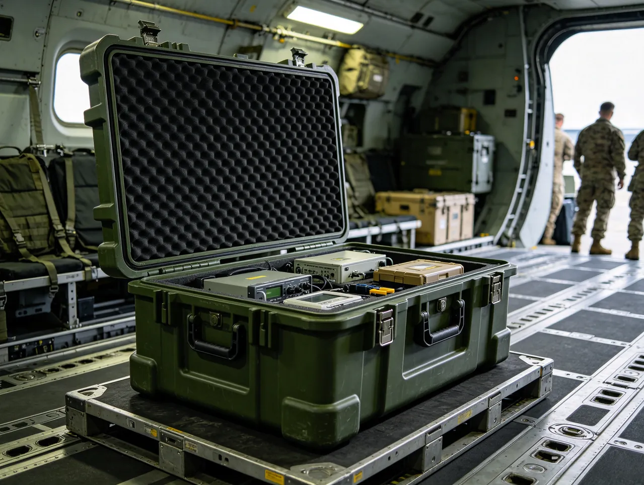
The Buchholz relay is the priority. It is a glass and metal instrument with a float and a delicate terminal, so it travels in a rigid mini-box with foam on all six faces and a do-not-invert mark, because tipping it can jam the float and give a false alarm at commissioning. The breather is a sealed can of silica gel that must stay dry, so it gets a desiccant pouch of its own and a cap on the breather port, never left open to the case air. The relief and sampling valves are bagged and clipped to a labelled card so the receiving plant knows which port each serves.
The nameplate rides in a flat sleeve with a stiff backing, never loose, because a bent plate cannot be read and a lost plate is a documentation gap. Each sub-compartment is listed on the packing sheet with its part number, so the goods-in check can confirm the accessory set is complete before the main cavity is even opened. The discipline mirrors the compartment logic used for precision instruments in Precision Instrument Protective Cases.
Freeze-Thaw Cycling and Diurnal Condensation on Flatcar and Hatch Deck Routes
A transformer shipped on a rail flatcar or a ship hatch deck lives through a daily temperature swing that a works storeroom never sees. Daytime solar gain on a closed case can push the interior past 55 °C, and a cold night can pull it below freezing, so the contents cycle through freeze-thaw several times on a long route. Condensation forms when that warm wet air meets a cold metal surface, and the oil chamber and the bushing flange are exactly those cold surfaces.
JUNZHIJIA controls the cycle rather than fighting it. The case carries a desiccant charge sized to the internal air volume, not a token pouch, and a humidity indicator card shows whether the charge is still active at goods-in. A breather valve balances pressure so the case does not suck damp outside air when it cools, which is the usual way condensation starts. The liner keeps a drainage path so any water that does form runs to a low point away from the insulation and the weld seams, instead of pooling on a horizontal flange.
The freeze-thaw risk is sharpest for the bushing seal, because the elastomer hardens in the cold phase and over-compresses in the warm phase, losing recovery. The locating ring and free-space rule already covered protects it, and the ultraviolet shroud also cuts daytime heat gain. The same condensation control used for towers and exchangers is described in Heat Exchanger and Tower Parts Cases.
Coastal Salt Spray on Radiator Fins, Tank Steel and Threaded Fasteners
A coastal or sea route means salt, and salt is the one contaminant that keeps working after the case is opened. Radiator fins are thin sheet with narrow gaps, tank steel is a welded fabrication with bare edges, and threaded fasteners are the classic crevice corrosion site, so all three need a barrier before the case is sealed.
JUNZHIJIA applies the barrier at three levels. The fin zone gets a hydrophobic wrap that sheds salt mist and is removed at goods-in, because salt left between fins is almost impossible to flush out later. The tank steel edges and any exposed weld get a temporary corrosion inhibitor film, wiped on and recorded, so a delayed commissioning does not surface as rust at the seam. The fasteners are bagged with a vapour corrosion inhibitor, separately from the parts they hold, so the bag protects the thread while the part travels dry.
The case exterior also matters. A salt-resistant outer skin and sealed seams stop the salt reaching the liner, and the case is never left standing where deck spray lands directly. On arrival the exterior is rinsed with fresh water before opening, which removes the salt before anyone handles the contents. That rinse step is written into the opening sequence, because opening a salt-crusted case indoors just moves the salt onto the parts. The crevice protection principle is the same one used for machinery cases in Ceramic and Tile Machinery Cases.
Whole-Tank Lift Versus Component-Level Packing: A Trade-Off Audit
A purchaser sometimes asks why the transformer is not shipped as one tank with everything attached, since a single lift sounds simpler. The answer is a trade-off between handling mass and damage exposure, and component-level packing usually wins for the long international routes.
A whole-tank lift moves the largest mass in one piece, so the crane, the trailer and the rail wagon all have to be rated for it, and the bushing skirts and radiator fins then travel fully exposed on the tank, taking every impact directly. Component-level packing separates the bushing, the radiator bank and the accessories into their own cases, each sized to its own fragility, so the heavy tank goes one way and the brittle parts go another.
The audit weighs four things. Mass and handling: a split shipment needs more lifts but each is within standard equipment. Damage exposure: brittle parts in dedicated cases have far lower skirt and fin risk than parts bolted to a moving tank. Cost: more cases cost more to build but far less to repair. Schedule: a damaged bushing can hold a whole substation, while a damaged tank is rarer. JUNZHIJIA recommends component-level packing above 110 kV on multi-leg routes, and supports whole-tank consignment only where the route is short and the handling is controlled. The same split-versus-integral logic appears for large fabricated equipment in Casting Mold Transport Cases.
Three-Density Foam Gradients and Removable Sub-Compartment Construction
The liner is where most of the protection actually lives, and JUNZHIJIA builds it as a density gradient rather than a single block. A hard high-density layer at the case floor carries the load and levels the base. A medium-density layer shapes the part and takes the working impact. A low-density layer fills the fine gaps and locates without compressing, so the brittle face never meets a rigid wall.
The gradient solves the conflict between support and cushioning. Too hard and the skirt chips on a hard contact; too soft and the part sinks and the weld takes the load. By grading, the bushing root sits in medium density that limits excursion, the skirt tip sits in low density that gives way, and the oil chamber sits on high density that spreads the weight. Each layer is cut to the real outline, not approximated, because an approximate cavity leaves a void that becomes a hard contact after a few bounces.
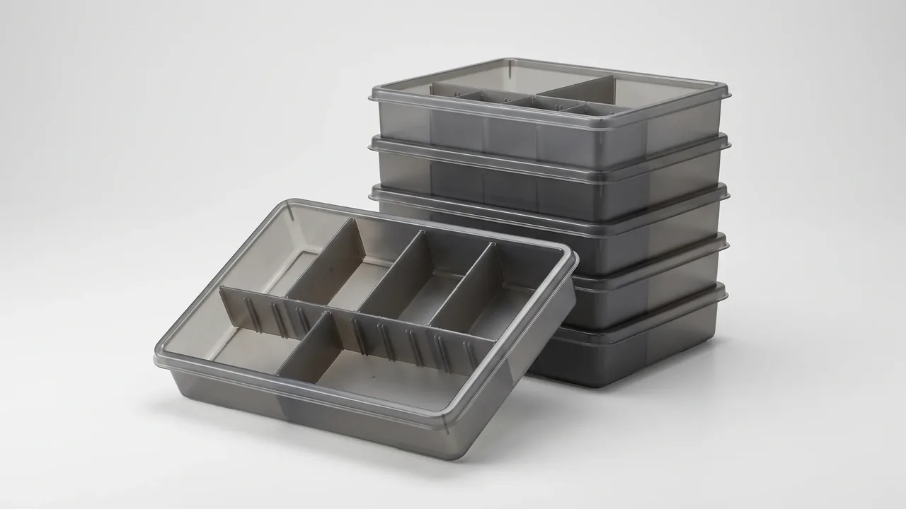
Sub-compartments are removable, not glued in. The accessory mini-boxes clip into the main liner and lift out as a unit, so the goods-in check can open one without disturbing the others, and a damaged liner layer is replaced without rebuilding the case. The clips are the same removable type used across the JUNZHIJIA range, so a receiving plant with several cases can share spares. The gradient and clip approach is the backbone of the moulded liner used for precision parts in Precision Instrument Protective Cases.
Goods-In Acceptance: Oil Level, Weld Leakage and Insulator Integrity
Goods-in acceptance is where packing pays off or fails, and JUNZHIJIA writes the check as a fixed sequence tied to the packing sheet. The sheet names each compartment and its control, so the receiving plant opens in the right order and records against the right line.
Oil level comes first for any chamber that ships with residual oil. The sight glass or dip is read after the case has stood open for two hours, because a cold chamber reads low and a warm one reads high; only a stabilised reading is meaningful. Weld leakage is the second check: the exterior is wiped dry and re-inspected after 24 hours for any returning film, separating a genuine seep from residual oil migration under temperature difference. Insulator integrity is the third: the bushing skirts are inspected under raking light for edge chips, the porcelain column for transverse cracks, and the epoxy body for any swelling or debonding at the end flange.
Each finding is written against its compartment line, and a discrepancy triggers a hold rather than a silent install. The record then closes the loop with the packing signoff, so a repeat defect is traced to the same compartment and the same control, and the next dispatch corrects it. That acceptance discipline is the same one applied to sealed and insulated equipment in Heat Exchanger and Tower Parts Cases.
Frequently Asked Questions FAQ
Q: Why does a transformer bushing chip at the skirt edge rather than fracture outright?
A: A bushing almost never fails in transit by puncture or flashover. It fails by a chip off the edge of a porcelain skirt, and the reason is geometry. On units of 110 kV and above the wall at the smallest skirt diameter is often only 8 to 15 millimetres thick, and the skirt end face is a free boundary, so the bending stress concentration factor at that edge routinely exceeds three. When the contents shift inside the case a wedge action develops: the foam compresses and pushes the bushing outward, a skirt tip bears on the arris of a foam bore, the contact patch collapses to a few square millimetres, and the peak pressure passes the compressive strength of porcelain almost at once. The chip is the size of a grain of rice and is easily missed under inspection lighting, then resurfaces as a breakdown during a later withstand or lightning impulse test. The packing answer is a single rule: no hard edge anywhere the skirt can reach. The compartment bore is wrapped continuously, openings are chamfered to a radius of the same order as the foam thickness, and no strap, batten or label plate lies on the skirt sweep path. A removable collar under the skirt root limits lateral excursion without carrying load.
Q: How do epoxy composite and porcelain bushings need different protection?
A: Porcelain and epoxy composite bushings fail by different mechanisms, so their packing targets are nearly opposite. Porcelain is a brittle ceramic: once the input energy passes the allowable level it fractures with no warning, an energy-controlled failure. Epoxy composite is a glass-fibre reinforced resin: under impact it shows delamination, fibre breakage and end-interface debonding, a progressive failure whose early phase is invisible from outside while internal microcracks accumulate. The practical consequence is that for epoxy the transport goal is not the absence of knocks but the limitation of cumulative impact. Along one route a porcelain bushing may pass visual inspection while the epoxy unit behind it already carries delamination that only dielectric loss or ultrasonic inspection will reveal. Three adjustments follow. A soft transition pad at the end flange to cast body joint reduces peeling at the edge of the cast body. The equipotential grading layer, where fitted, is never supported by anything hard, because a pierced grading layer drops discharge inception voltage sharply. And sustained compression is avoided, since foam sized for storage rather than transit leaves the resin statically loaded for months and the skirts take a permanent set only seen when the unit reaches its foundation.
Q: Why does the bushing seal lose capability while the case looks perfect?
A: The bushing seal, the flange gasket, the sealing ring and the oil-fill plug, is the most easily overlooked soft failure in the package, and it fails silently. The ring leaves the works under slight preload between ceramic and metal, commonly nitrile, fluorocarbon or silicone. Over a long haul the case interior may cycle between minus 20 °C and plus 55 °C: the ring hardens and loses recovery in the cold phase and is over-compressed in the warm phase. The signature is that the outer packaging looks perfect while the seal has already lost its capability, and the loss appears only after oil is filled on site, where the cost is high. The case design gives the ring its own constraints. Locate, do not clamp: a locating ring holds the radial position so vibration cannot make the ring migrate in its groove, and foam never bears on the ring, leaving interference at the level where the ring moves under finger pressure and returns when released. Leave the flange face hollow with 1.5 to 3 millimetres of free space so the gasket compresses evenly when bolts are tightened. Coat for protection with a peel-off ultraviolet screen or aluminised shroud, because long open-air storage before opening brings direct ultraviolet to the bushing.
Q: What actually causes radiator fin bending in transit?
A: Radiator fins are thin sheet, 0.8 to 1.5 millimetres in aluminium or cold-rolled steel, and they fail not by fracture but by bending combined with local buckling, which is a completely different mechanics from porcelain. The first shape is whole-group bow: an impact drives the radiator inside the case, the fin pack to oil chamber joint becomes the pivot, the pack swings about it, and because the thin-walled section yields plastically the deformation does not spring back. The result is uneven fin spacing and a temperature rise beyond rating. The second shape is local buckling at a fin root, a press brake fold or a weld heat-affected zone, where vibration on shock makes a local wrinkle and the section's moment of inertia then collapses. The governing fact is that fin stiffness is far lower across the fin than along it: bending stiffness scales with the cube of thickness, so 1.2 millimetre and 2.5 millimetre sheet differ by more than nine times in capacity. Restraint must therefore never be a single pressure point over a face; it has to be distributed normal support with tangential freedom. A shaped foam cradle follows the real geometry, supports the oil chamber over its full lower surface, and fills the fin zone with low density that locates without compressing, restraining both axes so no impact throws the pack to one side.
Q: How do you tell a genuine oil chamber leak from residual oil migration?
A: An oil film on the outside of a radiator oil chamber after a long coastal or cross-season haul is not automatically a leak, because residual oil inside the case can migrate under a temperature difference and wet the exterior without any seam failure. The packing isolates the chamber as though it were already full: low-density closed-cell foam fills 50 to 70 percent of the internal volume, not for cushioning but to stop relative sliding wear between the chamber wall and internal stiffeners, and a seal cap on the open end keeps warm transit vapour from re-wetting an uncleaned flange face. To confirm a genuine leak, the goods-in record uses one cheap test: wipe the exterior dry after the case has stood open for two hours, then check whether a film returns within 24 hours. A returning film means a real seep from a weld micro-crack or a flange face corrosion point, while a dry surface means migration only. The distinction matters because a genuine leak needs fluorescent or penetrant inspection and a repair before commissioning, whereas migration needs only a clean and a dry fill. The same oil-content judgement used for sealed fabricated items is in Heat Exchanger and Tower Parts Cases.
Q: Why oppose radiator flanges instead of facing them together?
A: In piece packing the fatal arrangement is placing two radiator flange faces directly against each other. Metal slides on metal and each scratch becomes a stress concentration site, and once the chamber takes load the two radiators are separated by a very short moment arm, so the whole package's resistance to overturning collapses. The correct posture opposes the flanges: the first radiator lies flange up, the second flange down, with 4 to 6 millimetres of continuous soft cushioning between them that covers the whole outer periphery outside the bolt holes, not just a few pads. The compartment is capped at three units, because beyond three the vertical stack load makes the lowest radiator carry the accumulated pressure and opposing fins rub, leaving scoring. Support is continuous, because a flat floor under a curved chamber stands the radiator on two points with a void beneath the middle and the chamber has already bowed under its own weight before the case closes. Flange parallelism also drives bolt entry: a flat bore against curved chambers forces a slight twist, the bolt holes move out of register, and the bolts cannot enter their original positions, so the compartment needs a flat relief on the bolt-hole side and a curved bearing opposite.
Q: What does the three-density foam gradient achieve that one block cannot?
A: A single foam block cannot both carry the load and cushion the brittle face, because those needs pull in opposite directions: too hard and the skirt chips on a hard contact, too soft and the part sinks and the weld takes the load. JUNZHIJIA builds the liner as a density gradient instead. A hard high-density layer at the case floor carries the load and levels the base. A medium-density layer shapes the part and takes the working impact. A low-density layer fills the fine gaps and locates without compressing, so the brittle face never meets a rigid wall. The gradient places each part in its right layer: the bushing root sits in medium density that limits excursion, the skirt tip sits in low density that gives way, and the oil chamber sits on high density that spreads the weight. Each layer is cut to the real outline, not approximated, because an approximate cavity leaves a void that becomes a hard contact after a few bounces. The sub-compartments are removable clips, not glued, so one accessory box opens without disturbing the others and a damaged layer is replaced without rebuilding the case. That gradient and clip backbone is the same moulded liner principle used for precision parts in Precision Instrument Protective Cases.
Q: When should a transformer ship as a whole tank rather than in components?
A: The choice between a whole-tank lift and component-level packing is a trade-off between handling mass and damage exposure, and component-level packing usually wins on long routes. A whole-tank lift moves the largest mass in one piece, so the crane, trailer and rail wagon must all be rated for it, and the bushing skirts and radiator fins then travel fully exposed on the tank, taking every impact directly. Component-level packing separates the bushing, the radiator bank and the accessories into their own cases, each sized to its own fragility. The audit weighs four things: mass and handling, where a split shipment needs more lifts but each stays within standard equipment; damage exposure, where brittle parts in dedicated cases have far lower skirt and fin risk; cost, where more cases cost more to build but far less to repair; and schedule, where a damaged bushing can hold a whole substation. JUNZHIJIA recommends component-level packing above 110 kV on multi-leg routes, and supports whole-tank consignment only where the route is short and handling is controlled.
Conclusion and Related Reading
JUNZHIJIA treats the bushing, radiator and accessories as independent load paths so skirt chipping, fin bending and seal loss stay inside their allowable values across the whole transport envelope.
Related Reading