

A waterjet cutting machine pushes water to between three hundred and four hundred megapascals and then releases it through a jewel orifice only 0.2 to 0.4 mm across. The accuracy and the service life of the whole machine rest on one very narrow high-pressure chain: the plunger and seals of the intensifier, the seats and poppets of the check valves, the cones of the high-pressure connectors, and the jewel orifice and mixing tube inside the cutting head. A score on any sealing face along that chain that is almost too faint to see will put the machine out of specification within tens of operating hours, and the symptom will simply be a loss of cutting capability that takes half a machine to diagnose.
The JUNZHIJIA approach to waterjet cases is to design crush protection and score protection with one logic. Waterjet parts behave in two opposite ways. Intensifier bodies and valve blocks are very hard metals whose sealing faces must never be scored or indented, while jewel orifices and ceramic parts are brittle and must never be struck. A single case has to keep hard faces unmarked and brittle bodies uncracked at the same time, which means differentiated compartments, differentiated restraint and differentiated foam, not one foam filling for everything.
Table of Contents
- Intensifier Pump Seal Faces: What a Micron-Scale Score Costs at 400 MPa
- Plungers and Seal Kits: Independent Compartmenting for Each Assembly
- Jewel Orifices and Mixing Tubes: Fragile-Part Compartments and Crush Control
- Abrasive Feed Lines: Low-Temperature Embrittlement and Kink Prevention
- Check Valves, High-Pressure Lines and Connector Cones: End-Face Protection
- Cutting Head Assemblies: Keeping the Three-Axis Mechanism and Cover Rigid
- Fragile-Part Compartment Design: Contact Faces and Acceleration Control
- Moisture Control: Residual Water, Salt Fog and Galvanic Corrosion
- Accumulators and Pressure Gauges: Shipping Pressurised and Instrument Parts
- Abrasive Hoppers and Tanks: Stacking, Sealing and Dust Containment
- Transport Testing: Shock Spectra and Vibration Thresholds for Fragile-Part Cases
- Incoming Inspection: Seal-Face Scoring Checks and Orifice Bore Verification
- Frequently Asked Questions FAQ
- Conclusion and Related Reading
Intensifier Pump Seal Faces: What a Micron-Scale Score Costs at 400 MPa
The intensifier is the pressure source of a waterjet system. A low-pressure hydraulic piston drives a high-pressure plunger that compresses water to working pressure. The bore wall, the plunger outside diameter and the seal interfaces together form a high-pressure sealing chain working at three to four hundred megapascals, which is roughly four thousand atmospheres.
At that pressure the critical defect size is minute. Hydraulic practice holds that once a score is deeper than the order of magnitude of the sealing film, a leakage path forms. The water film in a waterjet high-pressure seal is sub-micron, so a score only two or three microns deep is already enough to create a stable leak path. The observable symptoms are slow pressure build-up, pressure decay during hold, and rapid seal wear.
Scores usually do not come from impact. They come from contamination combined with relative movement. Vibration in transit lets the body shift a few microns against its liner, or lets two metal parts shift against each other, and if abrasive grit, abrasive residue or metal swarf is trapped between those faces the assembly becomes a ready-made lapping tool. A few hundred kilometres of road vibration is enough to grind a visible score. The first protection measure is therefore not thicker cushioning but thorough cleaning plus a rigid protective cover.
| Defect | Typical size | Effect on high-pressure sealing | Repairable |
|---|---|---|---|
| --- | --- | --- | --- |
| Surface score | 2 to 10 microns deep | Leak path, pressure decay | By lapping, may go undersize |
| Pitting | 0.05 to 0.5 mm across | Local leakage, seal damage | Depth dependent, usually replace |
| Mating-face indentation | 1 to 5 microns deep | Reduced contact ratio | By lapping |
| Rust bloom | Time dependent | Destroys surface roughness | Light cases only |
| Embedded abrasive | Tens of microns | Continuous lapping, fastest degradation | Requires full removal |
The correct sequence is to remove abrasive residue with high-pressure water or a water-based cleaner, blow every blind hole and thread dry with compressed air, apply a dedicated anti-rust grease to the sealing faces, and only then fit a rigid cover in metal or engineering plastic. The cover is not there to cushion; it is there to separate the sealing face from any soft material that could carry contamination.
Plungers and Seal Kits: Independent Compartmenting for Each Assembly
When an intensifier ships dismantled it usually separates into three groups: plunger, seal kit and cylinder body. Each needs a different restraint strategy, and mixing them is the most common error.
The plunger is a slender hard-metal or ceramic-coated steel part with an extremely fine surface finish, vulnerable to scoring and bending. It must never share a compartment with the cylinder body, because the mass of the body will score the plunger during any relative movement. The correct treatment is a dedicated long compartment with V-block supports at both ends, IXPE facing on the blocks, and a clearance of at least twenty millimetres from any metal part.
Seal components, including O-rings, support rings and back-up rings, are rubber and engineering plastic parts vulnerable to compression set and twisting. They belong in flat pockets, neither stood on edge nor stacked, because sustained load produces permanent deformation and early leakage after assembly.
The cylinder body is large and heavy and requires its own compartment with three-point support. Its bore must stay empty in transit, and no desiccant sachet should ever be placed inside it, because desiccant beads that lodge in a corner and escape cleaning become a contamination source. Where a body is too heavy for a single case, split the shipment so that the body travels alone rather than sharing a compartment with smaller parts that it can crush under vibration.
| Component | Material | Failure mode | Restraint | Prohibited practice |
|---|---|---|---|---|
| --- | --- | --- | --- | --- |
| Plunger | Hard metal, ceramic coated | Scoring, bending | V-blocks in dedicated long pocket | Sharing with cylinder body |
| Seal rings | PU, NBR, PTFE | Flattening, twisting | Flat pocket, no stacking | Stuffed into a tight bag |
| Cylinder body | Alloy steel | Bore scoring, corrosion | Three-point support, bore plugged | Soft material in the bore |
| Support rings | Engineering plastic | Fracture | Individual small pocket | Mixed with metal parts |
Jewel Orifices and Mixing Tubes: Fragile-Part Compartments and Crush Control
The jewel orifice is the most fragile, most expensive and most easily damaged part on a waterjet machine when it comes to small-part packing. Its bore runs 0.2 to 0.4 mm, and it is made of sapphire or diamond, materials of extreme hardness but very low fracture toughness. Mixing tubes, usually tungsten carbide or ceramic composite, are equally brittle and have a high length-to-diameter ratio, making them thin-walled brittle tubes.
The failure threshold is low: a one-metre drop onto a hard surface, or sustained vibration that lets parts strike each other, is enough to chip or crack them. The more insidious outcome is micro-chipping, where the orifice edge loses a few microns. It is nearly invisible to the eye but immediately changes the jet shape, producing striations on the cut face and reducing cutting capability.
Three principles govern fragile-part protection. Fragile parts must not coexist, meaning a brittle part never shares a pocket with a metal part and never touches another brittle part, so each gets its own compartment. Soft wrap with hard limit means the brittle part is fully wrapped in soft foam, and that wrapped package is then restrained to zero freedom by a hard stop, so the foam cannot compress and leave room to move. Acceleration control means the liner thickness and case stiffness are chosen so that the peak acceleration reaching the brittle part stays within what the material tolerates.
| Fragile part | Material | Typical failure | Protection | Storage attitude |
|---|---|---|---|---|
| --- | --- | --- | --- | --- |
| Jewel orifice | Sapphire | Bore-edge chipping | Own pocket, soft wrap, hard stop | Any attitude, no load bearing |
| Diamond orifice | Polycrystalline diamond | Fracture | Own pocket, anti-roll | Laid flat |
| Mixing tube | Tungsten carbide composite | Wall cracking | Long pocket, V-block | Horizontal |
| Ceramic valve core | Zirconia ceramic | Edge nicking | Individual small pocket | Flat, not stacked |
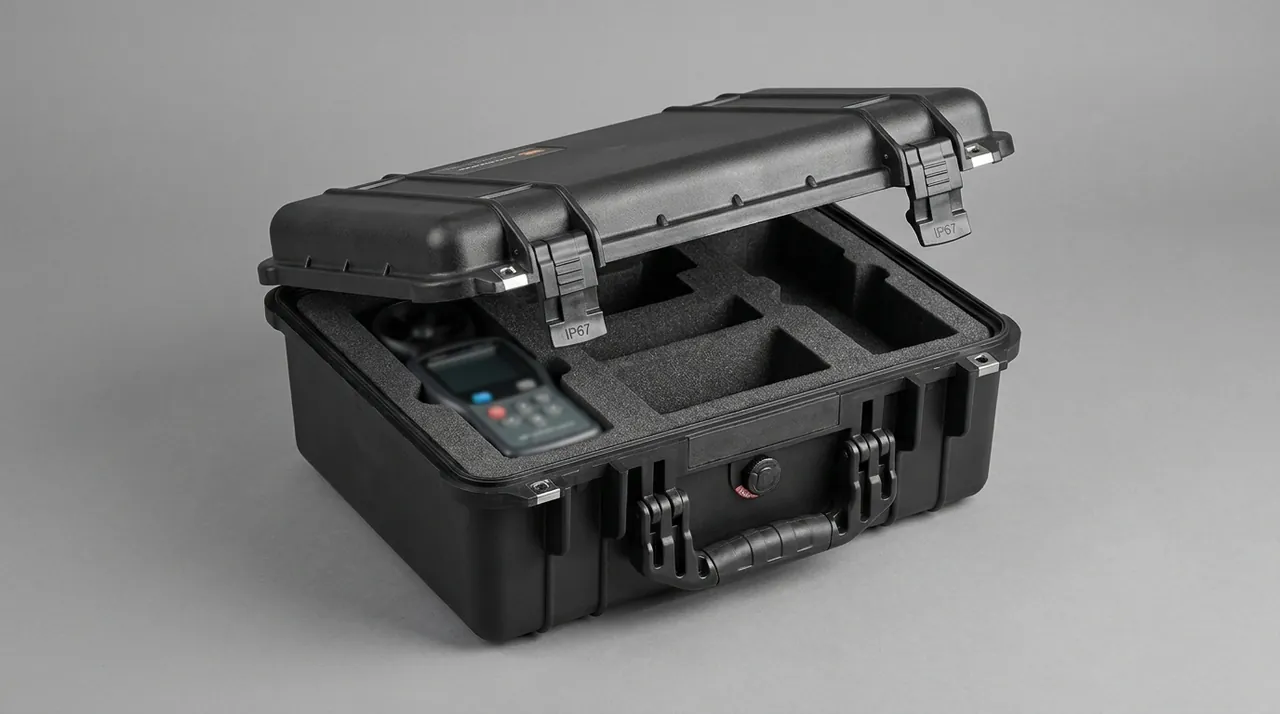
Abrasive Feed Lines: Low-Temperature Embrittlement and Kink Prevention
The abrasive feed line carries abrasive from hopper to cutting head and is normally a polyurethane or special rubber hose with a wear-resistant bore and a pressure-resistant cover. Both of its risks are temperature related.
The first is low-temperature embrittlement. Polymers transition from ductile to brittle below their glass transition temperature, and an ordinary polyurethane hose stiffens noticeably at around minus twenty degrees Celsius, at which point bending or impact readily causes cracking. Winter transport in northern regions and shipments routed through high latitudes can both fall inside that band, as described in low-temperature brittleness in protective cases.
The second is bending fatigue. Hoses are often coiled to save space, and if the coil radius is too small the inner wall is compressed while the outer wall is stretched, which produces permanent deformation during storage. Vibration in transit then loads the bend repeatedly, concentrating stress until a crack starts.
The protective measures are straightforward. Coil the hose to a radius no smaller than its minimum bend radius, secure the shape with soft ties rather than metal clamps, place it in its own compartment and restrain its freedom. Where the route crosses cold regions, choose liner materials that stay flexible at low temperature, such as low-density IXPE or microcellular polyurethane, and avoid ordinary EPE that stiffens in the cold.
| Temperature band | Hose condition | Dominant risk | Response |
|---|---|---|---|
| --- | --- | --- | --- |
| Above 5 degrees Celsius | Flexible | Bending fatigue | Control coil radius |
| 0 to minus 10 | Slightly stiff | Stress concentration at bends | Larger radius, secure shape |
| Minus 10 to minus 25 | Clearly brittle | Impact cracking | Insulation plus soft buffer |
| Below minus 25 | Brittle | Cracking at rest | Remove and pack separately |
Check Valves, High-Pressure Lines and Connector Cones: End-Face Protection
High-pressure check valves and connectors are among the most precisely machined parts in a waterjet system. Connectors usually seal metal to metal on a cone, with an angular tolerance measured in minutes of arc and a surface roughness within Ra 0.4. Once a cone is indented or scored, the joint leaks at pressure, and it leaks in the most awkward way: pressure builds but will not hold.
The governing packaging rule is that nothing may contact a sealing cone. Many operations wrap connectors in foam, and the foam fibres then score the cone under vibration. The correct method is a dedicated plastic cap over the cone with a clearance of at least half a millimetre, followed by cushioning and restraint applied to the outside of that cap.
Threads are also vulnerable. High-pressure threads are usually fine pitch, and a knock in transit damages the crest so that the fitting either will not run home or seizes. Thread protectors are standard practice, but the protector must never press on the sealing cone.
| Feature | Precision requirement | Dominant failure | Protection |
|---|---|---|---|
| --- | --- | --- | --- |
| Sealing cone | Angular minutes, Ra 0.4 | Scoring, indentation | Cap with clearance |
| Threads | Fine pitch | Crest damage, seizure | Thread protector |
| Valve seat bore | Micron-level roundness | Scoring, distortion | Bore plug plus end cover |
| Poppet | Micron clearance fit | Sticking, galling | Individual small pocket |
Cutting Head Assemblies: Keeping the Three-Axis Mechanism and Cover Rigid
A waterjet cutting head is a small multi-axis mechanism containing X and Y movements, sometimes Z and tilt, plus bellows covers, water lines and an abrasive inlet. Its character is hard outside, delicate inside: the cover looks robust while the rails, screws and precision sliders inside are not.
Two risks dominate in transit. If the head rests on its own bellows cover, the cover deforms and later interferes with the rails after reassembly. If the head is left free to move, the axes oscillate under vibration, the screws and sliders see alternating loads, and cables and air lines fatigue at repeated bends.
Treat the head as a free body. Lock every axis in a fixed position with a transport locking device, usually a dedicated pin or clamp, then place it in its own compartment with supports bearing on the structural body rather than the cover, and finally restrain movement in all three directions with stops. Cables and air lines should be disconnected at the fittings, the fittings capped against dust, and the cables coiled and packed separately.
The locking device deserves as much attention as the compartment. A pin that relies on friction, or a clamp tightened against a painted surface, will loosen over a long sea leg and let the axes drift just enough to fret the rail surfaces. Positive engagement into a machined hole or a purpose-made groove is the reliable pattern, and the device should be marked so that it is removed before the first power-up rather than after a collision.
Fragile-Part Compartment Design: Contact Faces and Acceleration Control
The objective of a fragile-part compartment is to reduce the peak acceleration reaching the brittle part while guaranteeing that the part cannot be squeezed by anything else in any attitude.
The basic technique is the isolation-plus-limit combination, commonly built as a two-layer liner. The inner soft layer absorbs high-frequency, low-amplitude vibration, while the outer harder stop limits displacement when a larger shock occurs. The critical detail is that the two layers must not be the same material, or the grading effect disappears.
Contact faces must meet three conditions: the contact area should be as large as practical to reduce contact stress, the contact material should be softer than the brittle part so it cannot score it, and the material must not shed. Silicone and low-density IXPE are common choices, with microcellular polyurethane preferred where damping is needed.
| Layer | Suggested material | Thickness | Function | Common error |
|---|---|---|---|---|
| --- | --- | --- | --- | --- |
| Inner soft liner | Silicone, low-density IXPE | 5 to 10 mm | Absorbs high-frequency vibration | Ordinary EPE that sheds |
| Middle wrap | Microcellular polyurethane | 10 to 20 mm | Damping and shape adaptation | Same material as inner layer |
| Outer stop | High-density EVA, plastic block | As required | Limits displacement | Contacting the part directly |
| Inter-compartment divider | Rigid PE board | 5 to 10 mm | Separates fragile neighbours | Half-height divider only |
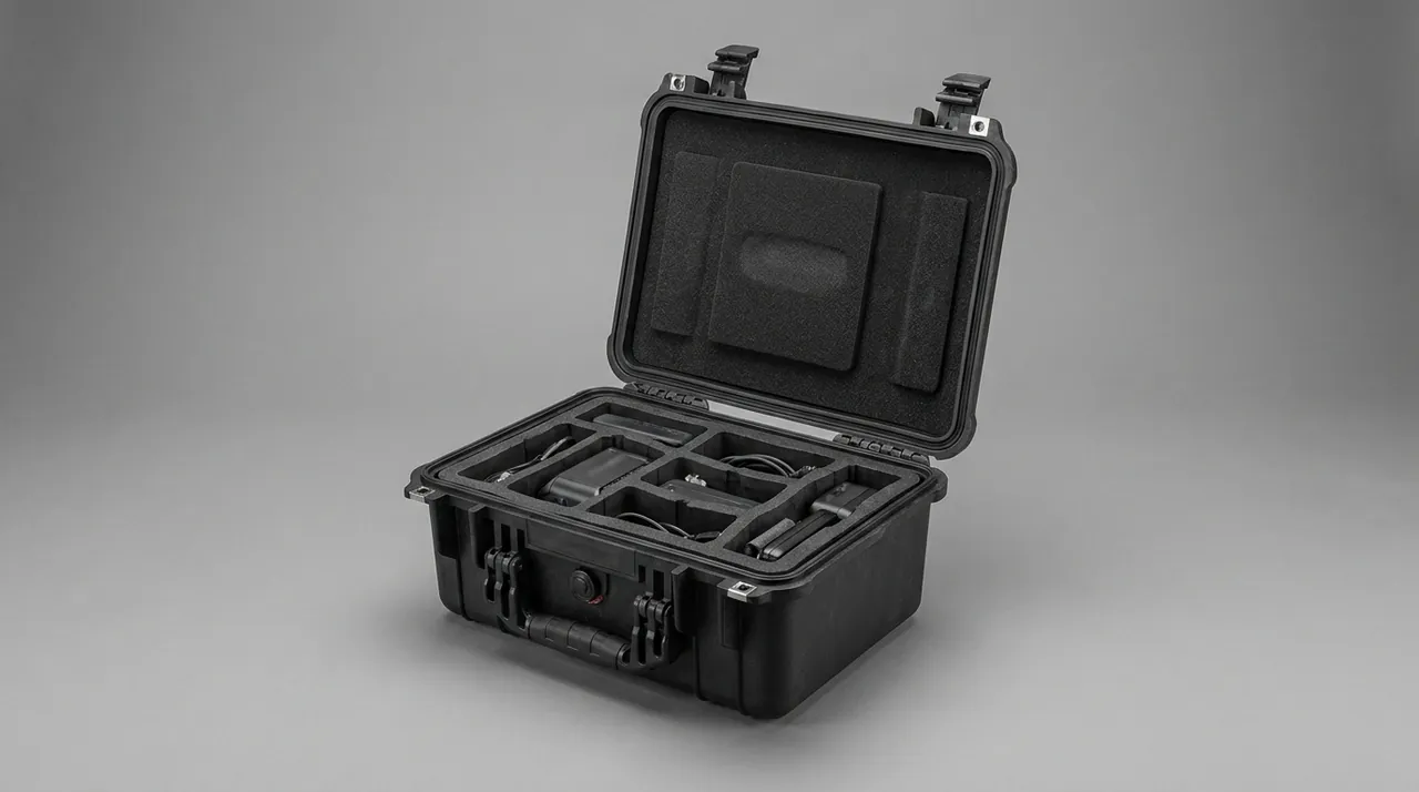
Moisture Control: Residual Water, Salt Fog and Galvanic Corrosion
Waterjet components are intrinsically associated with water, and residual water is the most easily overlooked corrosion source. The intensifier bore, accumulator, pipework and cutting head interior can all retain water after dismantling, and temperature swings in transit drive repeated freezing and evaporating-and-condensing cycles that are more aggressive than continuous immersion.
Moisture control has three steps. Drain and dry first: blow every water passage dry with compressed air before packing, paying particular attention to blind holes and low points, and confirm the part is dry before plugging any opening. Manage the case interior second: size desiccant to the free volume and pair it with a humidity indicator card, matching the desiccant quantity to the sealing class of the case. Protect metal surfaces third: apply rust-preventive oil to all metal surfaces outside the sealing faces, and use anti-rust grease plus a protective cap on the sealing faces themselves.
Salt fog matters mainly on sea freight. A chloride-laden marine atmosphere will penetrate even stainless steels, and sulphur-bearing environments accelerate pitting. The test methods are described in salt spray corrosion testing. A case sealed to IP67 limits salt fog ingress, but only if the gasket is intact and the breather valve carries a hydrophobic membrane; selection guidance is in pressure equalisation valves for cases, and the causes and control of internal condensation are covered in condensation control inside cases.
Accumulators and Pressure Gauges: Shipping Pressurised and Instrument Parts
An accumulator smooths pressure pulsation and contains either a pre-charged gas volume with a bladder or a piston. Before shipment it must be handled according to the maker's instruction, which means either fully depressurised or left at a specified transport pre-charge pressure. It must never travel at working pressure.
Pressure gauges, pressure transducers and flow meters are instrument parts whose weak points are the Bourdon tube, diaphragm or sensing element inside. Sustained vibration produces zero drift or fatigue failure in those elements. They should be removed from the pipework and packed in an instrument case: dial facing up or to the side, never facing down under load; the fitting must not carry weight; and two instruments must never be stacked in one pocket. Every fitting should be capped immediately after removal.
| Component | Pre-shipment action | Packing method | Key note |
|---|---|---|---|
| --- | --- | --- | --- |
| Accumulator | Depressurise or set transport pressure | Rigidly fixed, gas port plugged | Never at working pressure |
| Pressure gauge | Remove from pipework | Instrument pocket, dial unloaded | Never stacked |
| Pressure transducer | Remove, cap the port | Individual small pocket | Protect the connection |
| Flow meter | Drain and blow dry | Own pocket, upright | Keep debris out |
Abrasive Hoppers and Tanks: Stacking, Sealing and Dust Containment
Abrasive hoppers and tanks are structurally simple but are often the bulkiest items in a shipment, which drives different requirements for stacking and sealing.
Abrasive tanks normally travel empty, with abrasive bagged separately. An empty tank is far less stiff than a full one, so stacking deforms it, and deformation then disturbs the alignment with the discharge mechanism. Empty tanks should therefore not be stacked in multiple layers, or should be stacked with temporary internal support rings, or should have full-area boards between them so the load passes into the flange rather than the shell. The flange is the one feature engineered to take load, and routing force into it instead of the shell is the whole point of the board.
Hoppers raise a sealing issue. Abrasive left inside will escape through gaps under vibration and settle on other components in the case, becoming an abrasive contaminant. Empty and wash the hopper thoroughly before packing, dry it, inspect all welds and flange joints, and apply temporary sealing tape where necessary.
The abrasive itself needs attention too. If an abrasive bag shares a case with other components and the bag splits, the whole case is contaminated. Abrasive should ship in its own case, or at minimum in a sealed secondary bag placed at the top of the case. Bags should be handled as a contamination risk throughout, which means no cutting them open above an open case and no storing opened bags in the packing area.
Transport Testing: Shock Spectra and Vibration Thresholds for Fragile-Part Cases
Transport testing for a waterjet case differs from ordinary equipment packaging. An ordinary case is judged on whether the shell survives and the payload stays put; a waterjet case is judged on whether brittle parts stay unchipped and precision faces stay unscored, and neither defect shows in the case exterior. The test plan therefore needs targeted adjustment.
| Test | Reference | Adjustment | Acceptance focus |
|---|---|---|---|
| --- | --- | --- | --- |
| Random vibration | ISTA 3E, ASTM D4169 | Longer duration covering 3 to 20 Hz and the high band | Part displacement, liner collapse |
| Fixed-frequency sweep | GB/T 4857.7 | Locate and avoid the case first mode | Resonance amplification |
| Drop | GB/T 4857.5 | Corner, edge, face order, fragile end first | Chipping of fragile parts |
| Compression stacking | GB/T 4857.3 | Actual empty-tank stack height | Shell distortion, flange load |
| Low pressure | Mode dependent | Required for air freight | Case and gasket condition |
Hidden damage in brittle parts cannot be judged visually. After testing, open the case and inspect orifice edges and cones under magnification, then verify sealing face condition with a leak method. The procedures in airtight leak testing for cases transfer directly to factory pressure-hold verification of high-pressure pipework.
Incoming Inspection: Seal-Face Scoring Checks and Orifice Bore Verification
Incoming inspection of waterjet parts must go down to surface level, because much of the damage only surfaces as "pressure will not build" or "the cut face is rough" during commissioning, at which point the cause is impossible to attribute.
A four-step protocol works well. Inspect the case first: gasket intact, no abnormal compression marks, no escaped abrasive inside, humidity indicator card within limits. Inspect part surfaces second: examine sealing cones, seat bores and plunger outside diameters under a magnifier for scores and indentations, and check cone contact ratio with a print method. Inspect orifices third: verify bore condition with a go-no-go gauge or under a microscope, and inspect mixing tube bores with a borescope for cracking. Verify function fourth: pressure-hold test the intensifier, leak or hydro-test the high-pressure lines, and manually check each cutting head axis plus the reset of the locking devices.
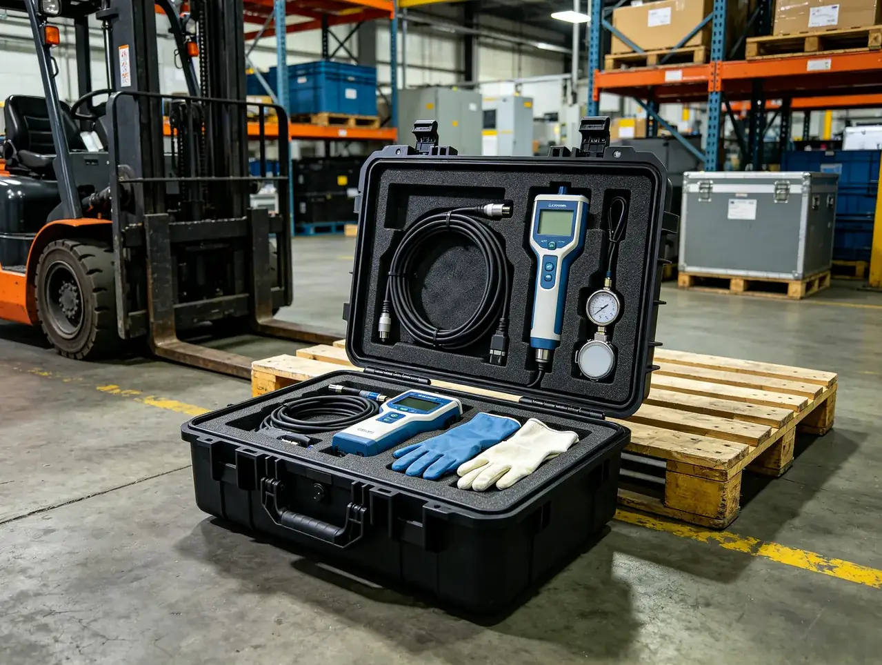
The acceptance criteria belong in the technical agreement: no visible score on any sealing cone, orifice bore chipping wider than three percent of the bore diameter to be rejected, and no axial score permitted on plunger outside diameters. Inspection must be completed within a stated number of days after arrival, beyond which responsibility becomes impossible to establish.
Frequently Asked Questions FAQ
Q: Why does an intensifier seal face pass factory inspection yet leak after transport?
A: Because high-pressure sealing is extremely sensitive to defect size, and the defect usually forms during transport. At three to four hundred megapascals the sealing film between mating faces is sub-micron, so a score or indentation only two or three microns deep is enough to create a stable leak path. Such scores are rarely caused by impact. They come from micron-level relative movement driven by vibration combined with abrasive residue, because a single abrasive particle trapped between two sealing faces means that a few hundred kilometres of road vibration performs a complete lapping operation. Factory inspection passing therefore says nothing about the condition on arrival. What matters is whether abrasive residue was fully removed before packing, whether a rigid cap kept soft liner material away from the sealing face, and whether the assembly was restrained so it could not move inside the case. A pressure-hold record taken before dispatch and repeated on arrival is the only clean way to assign responsibility.
Q: The jewel orifice is tiny, so why does it justify an individual compartment and a two-layer liner?
A: Because the cost of failure is far higher than the price of the part. A jewel orifice has a bore of only 0.2 to 0.4 mm, and a few microns of edge chipping is invisible to the eye while immediately changing the jet shape. The visible results are striations on the cut face, reduced cutting speed and higher abrasive consumption. This kind of functional degradation is very hard to diagnose on site, so attention usually goes first to pump pressure, abrasive quality and cutting parameters, and the investigation can run for weeks while the whole cutting line loses capacity. An individual compartment and a two-layer liner are a one-time cost that removes repeated stoppages and misdiagnosis. An orifice that has chipped cannot be repaired at all, and even a replacement requires re-establishing cutting parameters, which on a production machine may consume the better part of a shift in scrap and lost output.
Q: When an abrasive feed line cracks in winter shipping, is that a material problem or a packaging problem?
A: Usually both, but the packaging design has to cover the temperature limits of the material regardless. Polyurethane and rubber hoses stiffen sharply as they approach their glass transition temperature, and ordinary formulations enter the brittle range at around minus twenty degrees Celsius. If the case liner is ordinary EPE, which also stiffens in cold weather, impact energy arrives at the hose almost undamped and a crack forms at the bend. Two improvements address this. First, raise the low-temperature capability of the packaging itself by choosing liner materials that stay flexible when cold, such as microcellular polyurethane or low-density IXPE, and by adding buffer layers at the ends and at the bends. Second, remove stress concentration structurally: coil the hose to at least its minimum bend radius, secure the shape with soft ties rather than metal clamps, and then restrain it inside the case. Where a line has already been coiled tightly for a long period, inspect it at the bends before packing in the next one.
Q: Why must a high-pressure connector cone never be wrapped directly in foam?
A: Because foam sheds particles under vibration and those particles act as lapping compound. High-pressure connectors seal metal to metal on a cone, with an angular tolerance measured in minutes of arc and a surface finish within Ra 0.4. If foam fibres or debris become trapped between the cone and its wrap, the relative movement in transit rolls that debris repeatedly across the cone and cuts scores several microns deep. Such scores are invisible during assembly but leak above three hundred megapascals, and they leak in the awkward pattern where pressure builds but will not hold. The correct approach is a dedicated plastic cap over the cone with at least half a millimetre of clearance so the two never touch, with cushioning and restraint applied outside the cap. Protect threads with thread protectors as well, and make sure the protector never presses on the sealing cone. Keeping caps colour-coded by port type removes any doubt about which protection belongs where during reassembly.
Q: Why is residual water in waterjet parts more dangerous than external humidity?
A: Because residual water creates repeated wet-and-dry cycling, and cycling attacks metal faster than continuous immersion. The intensifier bore, accumulator, pipework and cutting head interior can all retain water after dismantling. As temperature swings between day and night during transit, that water freezes at low temperature, then melts and evaporates as things warm up, leaving the metal surface alternating between a liquid film and a dry state in which oxygen is continually replenished. Corrosion rates rise sharply as a result. If the residual water also carries abrasive or mineral salts, the attack accelerates further. Freezing brings a mechanical risk as well, because expansion stresses blind holes, thread roots and thin walls. Draining and blow-drying before packing is therefore mandatory, with particular attention to blind holes, low points and thread roots, followed by plugging every opening. The same discipline should be written into the dismantling procedure that precedes packing, not left to whoever is available on the day.
Q: How should accumulators, pressure gauges and similar pressurised or instrument items be handled?
A: An accumulator must be brought to the transport state specified by its maker, which normally means either fully depressurised or held at a stated pre-charge pressure, and it must never travel at working pressure, because shock loads superimposed on internal pressure impose extra load on the bladder or piston. Gas ports need capped plugs with seals to prevent slow loss of pre-charge and to keep contaminants out of the gas cavity. Gauges, transducers and flow meters should be removed from the pipework and packed in an instrument case with the dial facing up or sideways, never facing down under load, with no weight carried through the fitting, and never two instruments stacked in one pocket, since stacking applies uneven pressure to the case and can damage the dial glass and pointer. Cap every fitting immediately after removal so dust cannot enter the movement and cause zero drift or sticking, and record the pre-shipment reading of every instrument so a zero shift can be identified rather than argued about.
Q: How does transport testing for a waterjet case differ from testing ordinary equipment packaging?
A: The pass criteria differ. Ordinary equipment packaging is judged on the shell surviving and the payload staying in place, whereas a waterjet case is judged on brittle parts remaining unchipped and precision sealing faces remaining unscored, and neither of those defects appears in the case exterior. Three adjustments follow. Random vibration must cover both the low and high ends of the spectrum and run longer, because sealing-face scoring and abrasive embedding are cumulative effects. Fixed-frequency sweeping must be used specifically to find the case first natural frequency and confirm it avoids the 3 to 20 Hz band where road freight concentrates energy. Drop testing must run in corner, edge and face order with the fragile end treated as a priority direction. After testing, the case must be opened for magnified inspection rather than judged from the outside. A test report that records only case condition and payload position has tested almost nothing that matters on this equipment.
Q: At incoming inspection, how do you establish that a scored sealing face is a transport issue rather than a manufacturing defect?
A: By establishing a traceable factory baseline and comparing against it item by item instead of judging whether a score simply exists. A technical agreement should define three things. First, the maker supplies a factory inspection record covering at minimum a contact print photograph of each sealing cone, plunger surface roughness, orifice bore diameter with magnified photographs, and intensifier pressure-hold data. Second, the agreement fixes the arrival inspection method: magnified examination of cones and plungers, contact-print verification of cone contact ratio, go-no-go or microscopic orifice checks, and borescope inspection of mixing tube bores. Third, it fixes acceptance limits and an inspection deadline, for example no visible score permitted on any sealing cone, orifice chipping wider than three percent of bore diameter rejected, and no axial plunger scoring, with inspection completed within a stated number of days. The internal logger adds supporting evidence.
Conclusion and Related Reading
Waterjet packaging must satisfy two opposite demands in one case: precision faces that nothing may score, and brittle bodies that nothing may strike. Rigid caps, cleaning, individual compartments and acceleration control answer both.
Related Reading