

Relocating a wire drawing line has an odd characteristic: the big items rarely cause trouble, and what fails is the small hardware in the drawer. A drawing die is no bigger than a thumb and its bearing land is a fraction of a millimetre long, with a working surface specified at Ra 0.025 micrometre. One rub against a neighbouring die during packing leaves a ring mark on that mirror, and once wire is threaded the surface shows a bamboo-joint defect immediately. A spooler looks robust, but a flange that distorts by 0.5 mm makes level winding impossible, the wire piles into a cone on the reel, and it snaps when it pays off. As for residual drawing soap and saponified lubricant, inside a sealed case they absorb moisture, ferment and turn into a mildly alkaline paste that rusts die seats and bearing seats together.
The protection logic for wire drawing parts is not "wrap it up" but "set a contact boundary for each mirror grade and fit class." Mirror surfaces accept soft, non-contact support only. Die cores must never take an axial impact. Spooler flanges must never carry load. Capstan grooves must never be used as locating surfaces. JUNZHIJIA sorts drawing-line parts into three bands, mirror grade, fit grade and brittleness grade, then fixes support, compartment, rust prevention and moisture control for each item before choosing shell structure and stacking method.
Table of Contents
- Mirror-Finish and Edge Protection for Carbide Wire Drawing Dies
- Graded Packing for PCD and Natural Diamond Dies
- Groove Profile and Coating Protection on Drawing Capstans
- Runout Limits and Anti-Distortion Support for Spoolers
- Preserving Dynamic Balance in Cone Pulleys and Tension Arms
- Draining Emulsion Residue from Die Boxes and Cooling Jackets
- How Drawing Soap and Saponified Residue Affect Case Cleanliness
- Indexed Storage Against Loss of Small-Diameter Drawing Dies
- Rust-Proof Packing for Spooler Bores and Bearing Seats
- Impact and Impression Control on Helical Capstan Grooves
- Axial Load Capacity and Anti-Roll Restraint in Spooler Stacking
- Arrival Inspection and Trial Drawing Verification
- Frequently Asked Questions FAQ
- Conclusion and Related Reading
Mirror-Finish and Edge Protection for Carbide Wire Drawing Dies
A carbide drawing die consists of a tungsten-carbide cobalt core pressed into a steel casing, either hot or cold fitted. The bore is not a simple hole. It is a continuous surface made of an entry cone, a lubrication cone, an approach cone with a reduction angle usually between 8 and 16 degrees, a bearing land and an exit cone. The bearing land is normally 0.5 to 1.5 times the wire diameter, and it fixes the final wire diameter and roundness after drawing. The whole working surface is commonly held at Ra 0.025 to 0.05 micrometre, which is why it is called a mirror.
Two failure paths dominate.
| Failure mode | Trigger | Packing measure |
|---|---|---|
| --- | --- | --- |
| Ring scoring in the bore | Relative rubbing between die working faces, or against bolts and shims | One die per pocket, soft pocket wall, never two dies together |
| Chipped bearing land | Radial impact on the core edge, or a drop onto the casing | Full circumferential soft wrap, pocket floor takes no core weight |
| Core loosening, fit failure | Axial shock reaching the press fit | At least 10 mm axial clearance at both ends, no axial stacking |
| Scored entry cone | Wire fragments and soap left in place before packing | Ultrasonic clean, reverse blow, individual PE bag |
Die-to-die contact is the most commonly missed risk. A drawing shop may hold dozens of dies in one size, often grabbed into a small box with the working faces touching. Under vibration the entry cones press against each other over an extremely small area, so contact stress can reach hundreds of megapascals, enough to mark the mirror. Those marks do not cause an immediate break. They raise wire surface roughness and reduce adhesion of any subsequent plating, a textbook hidden defect.
The right practice is one die per pocket, core facing up, located on the casing outside diameter. Use IXPE or thermoformed EVA for the liner, with a pocket bore 0.5 to 1.0 mm smaller than the casing so the die is held elastically and cannot rattle, and a pocket depth 3 to 5 mm greater than the die height so the core touches no lid or bar. For large quantities, use two levels: a compartmented insert box holding one size, then that box treated as a single item in the outer case with a 10 mm cushion between layers.
Drying after cleaning is the other essential step. Cleaning liquid left in the bore absorbs moisture in transit and attacks the cobalt binder in the carbide, causing selective cobalt leaching. The result is a dull mirror with tiny pits. Carbide resists corrosion less well than steel, so this matters most in humid coastal climates. Comparable practice for precision dies appears in aluminium extrusion die transport protection.

Graded Packing for PCD and Natural Diamond Dies
By core material, drawing dies divide into four groups: tungsten-carbide, polycrystalline diamond, natural diamond and ceramic, often zirconia or silicon carbide. Their protection classes must be set separately rather than sharing one box.
| Core material | Typical hardness | Wire range | Brittleness | Packing focus |
|---|---|---|---|---|
| --- | --- | --- | --- | --- |
| Tungsten carbide | HRA 89 to 92 | Above 0.3 mm | Medium | Scoring first, chipping second |
| Polycrystalline diamond | HV 8000 to 10000 | 0.05 to 1.0 mm | High | Chipping first, elastic support essential |
| Natural diamond | Above HV 10000 | 0.01 to 0.2 mm | Very high | No hard contact at all, individual pack with orientation mark |
| Ceramic, zirconia etc. | HV 1200 to 1500 | 0.1 to 0.5 mm | High | Impact control, soft pad in pocket |
PCD and natural diamond share extreme hardness with low fracture toughness. PCD fracture toughness runs about 6 to 9 MPa·m<sup>1/2</sup>, and natural diamond is lower still with defined cleavage planes: loaded along a cleavage plane it splits at stress far below its compressive strength. That is why ultra-fine natural diamond dies are packed as glassware rather than as metal parts.
The grading shows up in three places. Support method differs: carbide dies can be held elastically on the casing outside diameter, whereas PCD and diamond dies must transfer load through the casing end face or a dedicated locating ring, with an annular rather than point support at the pocket floor. Compartment density differs: natural diamond dies warrant one die per pocket with at least 15 mm of liner wall between neighbours so shock cannot travel laterally, while PCD dies can share a box of two to four with internal dividers. Orientation marking differs too: natural diamond cores are directional, with different entry and exit cone angles, so mark orientation on the casing and keep all dies aligned so they cannot be fitted backwards.
For dies below 0.1 mm wire diameter the bore is open to the outside, and any stray fibre can enter. Plug both ends with a clean stopper immediately after cleaning, then pocket the die, and complete the packing step on a clean bench or in a soft-wall booth. Graded packing for diamond tooling follows similar logic to diamond wire saw and abrasive tool packing.
Groove Profile and Coating Protection on Drawing Capstans
A drawing capstan, also called a drawing drum or traction wheel, is the heart of a wire drawing machine. Diameters commonly run from 200 to 800 mm, and the surface carries multiple grooves in which the wire wraps and is pulled. Groove sections are V, U or R shaped, and groove profile accuracy governs both wrap pitch and tension distribution.
Groove surfaces are usually hardened by one of three routes: hard chrome plating at 20 to 80 micrometres, high-velocity oxy-fuel sprayed tungsten carbide at 0.1 to 0.3 mm, or laser cladding. All share high hardness, thin section and a bond line to the substrate that is the weak link. A concentrated impact on a groove edge can spall or micro-crack the coating, and a spalled area then grows quickly until the groove is locally dished and the wire runs off.
Packing rules follow. The groove must not act as a locating surface; locate the capstan on its bore or flange face and keep the entire groove area in free air. Protect the bore, which is often an H7 fit, with a plug or sleeve so debris cannot enter and score the wall during assembly. Cover flange faces, which mate with the spindle, with protective caps, and never apply tape directly to a coated area. For posture, stand the capstan on a dedicated saddle so the bore is horizontal or vertical, and never let it lie flat with the full weight bearing on the grooves.
There is a practical field check worth using. After packing, if the capstan can still turn slightly with nothing hard touching its outside diameter, the location is correct. If it will not turn at all, or turns with a scraping noise, some groove or coated area is in hard contact with the liner and the layout must be adjusted.
A capstan with spalled coating should not be repaired on site. Spraying requires grit blasting, preheating and dedicated equipment, and a field patch forms a worse bond line that later detaches and acts as a scraper on the wire. Record the location and area of spalling and arrange recoating or replacement.
Runout Limits and Anti-Distortion Support for Spoolers
A spooler, also called a reel or bobbin, winds wire in level layers for later pay-off. Materials include plastics such as ABS, PC or glass-filled grades, steel and aluminium, in standard sizes from DIN 100 to DIN 630, meaning flange diameters from 100 to 630 mm.
Two tolerances matter: radial runout and axial runout. Practice commonly allows 0.5 mm radial and 1.0 mm axial, tightened or loosened according to machine and wire diameter. Radial runout governs whether the wire builds a cone, and axial runout makes the traverse weave sideways and crushes layers.
| Failure mode | Trigger | Packing measure |
|---|---|---|
| --- | --- | --- |
| Flange ovalisation | Flange used as the stacking load face | Stack only through flange faces, or use a vertical rack |
| Flange face warping | Too many layers stacked flat for long periods | Calculate layer count against load, keep unit load within rating |
| Barrel distortion | Single reel weight resting on the barrel with poor support | Vertical support located on the bore, barrel carries nothing |
| Bore scoring | Debris inside the bore forced through during assembly | Bore plugs plus a blow-out before assembly |
The flange is the most misused feature. Stacking reels flat to save space puts flange directly on flange, so the full weight of upper reels presses on the flanges. A plastic flange is designed to resist wire tension, not axial stacking, and prolonged load ovalises it. An ovalised flange then vibrates periodically at high winding speed and directly degrades level winding.
Use a vertical rack that locates on the bore instead, holding each reel individually in its service posture. Where stacking is unavoidable, put annular spacers between reels so the spacers carry the interlayer load rather than the flanges, and keep a margin on the layer count. For large steel reels, DIN 500 and above, add anti-roll restraint, because a rolling disc destabilises the whole case.
Bore protection matters equally. The bore locates the reel on the spindle, usually at an H7 tolerance, and scoring it causes runout after assembly. Plug both ends with a dedicated stopper, plastic or softwood, and blow the bore clean before fitting.
Preserving Dynamic Balance in Cone Pulleys and Tension Arms
Cone pulleys, used for multi-pass drawing, are one-piece castings or weldments with stepped diameters. Tension arms maintain constant wire tension through counterweights and springs. Both share one requirement: dynamic balance must not be disturbed.
Cone pulleys are usually balanced to G6.3 or better, with residual unbalance coming mainly from casting segregation and uneven machining allowance. Transit does not create unbalance by itself, but impact-induced local deformation and mass loss after coating spallation do. Packing must therefore guarantee two things: no hard point contact anywhere, and no lifting or handling through the pulley rim.
Tension arms behave differently: their risk is that spring and counterweight posture changes. Arms are loaded by springs or cylinders, so release the spring or fit the transport stop described in the manual, and pack counterweights separately. If a counterweight travels on the arm, shock will shift it or loosen its fasteners, and the tension set point drifts. That drift is then re-calibrated on site with a tension meter, or, more often, quietly ignored.
Bearing seats on cone pulleys belong to the same accuracy class as spooler bores and need plugs or sleeves. Leave bearing-seat protection in place until the last moment before assembly, so nothing re-enters during handling. Where a seat already shows rust, dress it circumferentially with a fine oilstone and then measure two perpendicular diameters at the same cross-section to confirm cylindricity; replace the part or fit a bush if rust depth exceeds 0.02 mm.
Draining Emulsion Residue from Die Boxes and Cooling Jackets
In service, drawing dies sit in die boxes or holders, usually surrounded by a cooling jacket through which water or emulsion circulates to remove drawing heat. On teardown, both the box and the jacket inevitably retain liquid.
Retained liquid causes three problems. Freezing expands and bursts a thin jacket wall or opens a sealing face. Corrosion follows because drawing emulsion picks up metal fines and bacterial metabolites, so although fresh emulsion sits at pH 8 to 9, bacterial growth turns local areas acidic and pits copper and aluminium parts. Contamination is the third: under vibration the residue seeps through box joints, wets the liner and spreads into neighbouring compartments, taking the mirror parts with it.
Work in four steps: drain, rinse, dry, cap. Drain by removing the inlet and outlet fittings and blowing dry compressed air at 0.3 to 0.5 MPa from the inlet until no continuous liquid leaves the outlet, working through each chamber of a multi-chamber box. Rinse with clean water two or three times to remove the emulsion film, using one to two percent neutral cleaner first where odour indicates bacterial growth, then rinse again. Dry with compressed air and then in an oven at 60 to 80 degrees Celsius for 30 to 60 minutes, or air dry for more than 24 hours. Cap every water connection and label it as drained so that nobody connects cooling water before the first inspection.
Protect sealing faces on the jacket. An O-ring groove or flat sealing face with a 0.05 mm scratch will weep under pressure cycling, and the leak is usually blamed on the O-ring rather than on transit damage.
How Drawing Soap and Saponified Residue Affect Case Cleanliness
Dry drawing uses soap powder, typically calcium or sodium stearate or a compound, while wet drawing uses saponified or emulsified lubricant. The residue these leave on equipment is harder to handle than most people assume.
Drawing soap is largely a metal soap, and once it absorbs moisture it hydrolyses into free fatty acid plus calcium or sodium soap. Free fatty acid is mildly acidic and slowly corrodes steel, while the hydrolysed soap becomes a sticky paste that binds metal fines and dust into hard lumps. Those lumps then break loose under vibration and become free abrasive particles inside the case, where they score mirror surfaces directly.
Saponified residue carries a similar but more subtle risk. The dried film looks harmless, but it re-absorbs moisture as humidity rises, turns tacky, and supports microbial growth inside a sealed case, producing odour and acidic metabolites. This form of biological corrosion is especially common in long humid seasons.
Three controls apply. Grade the cleaning: mirror and fit surfaces need ultrasonic cleaning with a deionised water rinse and full drying, while non-mating parts such as frames and guards may be blown down, provided they never share a chamber with precision items. Verify with pH paper: press a deionised-water-dampened strip against the cleaned surface for one minute and expect a reading between 6.5 and 7.5, where an acid reading means fatty acid remains and an alkaline reading means soap was not rinsed away. Choose the liner with the chemistry in mind: IXPE and EVA resist soap solutions, whereas plain EPE foam swells and turns tacky, and paper or corrugated dividers embrittle quickly in soap residue and should be replaced with plastic.
Add desiccant at about 20 g per cubic metre of free volume and a humidity indicator card with 40, 50 and 60 percent thresholds. Note that desiccant does not replace cleaning. If a part goes into the case carrying soap, lowering humidity merely leaves the soap in place to re-absorb moisture on arrival. General rust-prevention practice for roll-type parts is described in metal rolling mill part protection and rust prevention.
Indexed Storage Against Loss of Small-Diameter Drawing Dies
The die count of a drawing line usually exceeds what operators expect. An eight-pass intermediate machine needs eight dies per line, and a shop with six lines, plus spares and different diameter configurations, easily exceeds two hundred dies. Outside diameters within one series differ by only 2 to 5 mm, which is hard to judge by eye, and fitting a die to the wrong pass puts the wire diameter straight out of tolerance.
Indexing is the only reliable answer, and it rests on four elements. Give each die its own pocket with a number matched to the pass, such as L1-1 for line one, pass one, printed on the foam and covered with protective film. Apply colour rings by diameter band, for example below 0.3 mm, 0.3 to 0.8 mm and above 0.8 mm, so a visual check is fast. Fill unused pockets with high-visibility plugs so a missing die is obvious both when closing and when opening. Attach a pocket list inside the lid showing position, size, bore, quantity, packer and date, laminated for returnable use.
For dies below 0.1 mm wire diameter, add a double marking of core orientation plus position number. Put a directional arrow on the casing outside diameter and stamp the position number on the casing end face. These dies are few in number but expensive, and losing one can cost more than the whole packing budget.
Rust-Proof Packing for Spooler Bores and Bearing Seats
Spooler bores and bearing seats are machined faces, turned or ground to Ra 0.8 to 1.6 micrometre, mostly on steel or cast iron reels, with plastic reels usually carrying a steel insert. These faces face both corrosion and impact.
Hand sweat, not just humidity, drives corrosion. An operator handling a machined face leaves chloride and lactate salts that start corrosion within hours, and visible rust appears within days in humid conditions. Once rust forms, assembly creates local high points and runout goes out of tolerance.
Packing therefore runs in three steps. Keep hands off: handle only with gloves after cleaning. Dry the case: use desiccant and a humidity indicator card targeting 60 percent relative humidity or below, switching to VCI film on machined faces for sea freight or humid routes. Wrap properly: plug the bore, cover bearing seats with VCI film and an outer PE bag, keeping the film within about 30 mm of the metal surface because VCI only works at short range, which is why loose wrapping fails.
Where light rust is already present, dress it circumferentially with a fine oilstone or lapping compound and then check cylindricity with a micrometer before assembly. Replace the part or fit a bush if rust depth exceeds 0.02 mm or if rust sits on a bearing raceway. Do not use abrasive paper by hand, because the abrasive grains embed in soft metal and become a new source of wear particles. Packing logic for coiled cable and wire products follows the same pattern and is covered in power cable accessory packing and moisture control.
Impact and Impression Control on Helical Capstan Grooves
Fine-wire and multi-head drawing machines often use one-piece capstans with a helical groove, in which the wire follows a continuous spiral. The spiral face is a series of connected grooves, and the ridges between them are thin and are the most fragile feature of the whole capstan.
Three defects dominate. Ridge impact produces a local rolled edge that scratches wire as it passes and disturbs the pitch of the neighbouring grooves. Groove-floor impressions form when the capstan rests on its grooved face, producing local depressions that make the wire bounce inside the groove and disturb tension. Spiral-face scoring follows from hard particles trapped in the liner, which drag a long scratch along the face under winding.
The packing principle is that the capstan locates on its bore or end face and the spiral face stays in free air. Fix the capstan on a mandrel through its bore and support it in a V-saddle, leaving 20 to 30 mm between the outside diameter and the liner, with a stop limiting axial movement. Where several capstans ship together, use a vertical rack with rigid shelves carrying the load so the spiral faces never take interlayer weight.
For ultra-fine wire capstans, where groove width can be only 0.1 to 0.3 mm, build a dedicated capstan chamber lined with lint-free soft material and bag the capstan in antistatic PE before placing it. The reason is that spiral faces attract dust readily, and dust trapped in a groove breaks the wire on the next threading. Load-bearing design for roll-type parts follows the support layout described in conveyor roller transport protection and anti-bow support.
Axial Load Capacity and Anti-Roll Restraint in Spooler Stacking
A spooler is round, heavy and able to roll. Those three properties together make stacking and restraint demands higher than for ordinary case contents.
For axial capacity, most of the strength comes from the flange faces and the barrel wall. Plastic barrels are usually thin-walled and carry limited axial load, often no more than 200 to 500 kg per reel, while steel reels reach 1 to 2 tonnes. Layer count must be calculated from the load capacity of the bottom reel divided by the total weight above, with a dynamic amplification factor applied. Road transport vertical acceleration peaks commonly reach 1.5 to 2.5 g, and sea freight can exceed that, so engineering practice divides the static result by a safety factor of 1.8 to 2.5.
| Reel type | Typical flange diameter | Static capacity guide | Suggested layers with dynamic factor | Restraint |
|---|---|---|---|---|
| --- | --- | --- | --- | --- |
| Small plastic | DIN 100 to 160 | 100 to 200 kg | 4 to 6 | Vertical rack plus chocks |
| Medium plastic | DIN 200 to 355 | 200 to 500 kg | 3 to 4 | Vertical rack plus annular spacers |
| Large steel | DIN 400 to 630 | 1 to 2 t | 2 to 3 | Dedicated skid, steel beams and straps |
| Aluminium | DIN 250 to 500 | 0.5 to 1 t | 2 to 3 | Skid with soft pads, no face scratching |
For anti-roll restraint, work at three levels: lock reel to reel with chocks or stops whose contact faces are treated for grip; lay an antislip mat of rubber or high-friction EVA on the case floor; and fit a transverse beam at least one third of the reel radius in height.
Balance the mass distribution as well. Reels are not perfectly symmetric, especially after wire has been wound and paid off, and the centre of gravity should sit near the geometric centre of the case so lifting does not tilt. In mixed loads, heavy reels go low and light reels high, and the case exterior should display the centre of gravity, the lifting points and a no-rolling warning.
Arrival Inspection and Trial Drawing Verification
Inspection must end at the only criterion that matters: the line draws acceptable wire. Work in three stages.
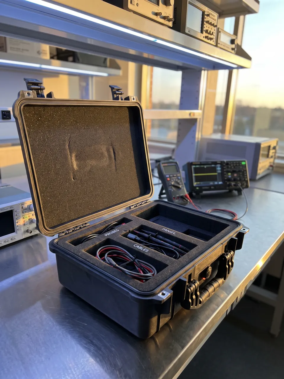
Stage one covers appearance and packing condition, checking case, seal, humidity card and VCI film, and rotating every mirror part under strong light with a magnifier or borescope to record any scoring location and length. Photographs must include case number and timestamp.
Stage two covers dimensions and accuracy.
| Part | Check item | Acceptance guide |
|---|---|---|
| --- | --- | --- |
| Drawing die | Bearing bore, roundness | Bore within drawing tolerance, often 0.002 mm, roundness 0.001 mm or better |
| Drawing die | Bore surface | No ring scoring or chipping, no dulling of the mirror |
| Capstan | Groove profile and coating | Profile gauge passes, coating not spalled |
| Spooler | Radial and axial runout | Radial 0.5 mm or less, axial 1.0 mm or less, per machine |
| Die box | Seal face and chamber | Seal face unmarked, no residual soap odour |
| Bore and bearing seat | Cylindricity, rust | No rust, cylindricity within tolerance |
Stage three is trial drawing. Thread the line under normal process conditions and raise speed in steps to working rate, watching three indicators: diameter stability, measured continuously with a laser gauge and staying inside the tolerance band, surface quality, with no bamboo joints, scoring or periodic ripple, and breakage rate, with no breaks in thirty minutes of continuous running. If the diameter runs large with rising variation, suspect a die in the wrong pass or residue in the bore. If the surface shows periodic patterning, suspect spooler runout or capstan groove damage. If breaks cluster at one position, inspect the guide rollers, die box exit and tension arm at that point.
A verification record should carry the case number, packing date, packer, part list with serial numbers, die position and bore, cleaning and drying records, desiccant and indicator batches, transport mode and duration, and the trial results. That record becomes the baseline for the next move, and it is the only way to tell transit damage from normal service wear.
Frequently Asked Questions FAQ
Q: Why should a carbide die bore mirror never be touched by bare hands?
A: Hand sweat is a mildly acidic electrolyte carrying chloride ions, and on carbide it forms a micro-cell within minutes in which the cobalt binder is preferentially leached. The mirror turns from bright grey to dull with tiny cobalt pits, and the damage does not recover after cleaning, because once cobalt is removed the tungsten carbide skeleton loses support and wears faster in service. A more immediate problem is that skin oil and sweat bind dust to the mirror, and those particles then act as abrasive grains under vibration, scoring ring marks inside the bore. Always handle dies with clean nitrile or latex gloves, since cotton gloves shed fibre, and touch only the casing outside diameter and end faces rather than the working core. After cleaning, wipe with a lint-free cloth and anhydrous ethanol, then bag the die immediately in a clean environment. If a die must be set down temporarily, place it core up on a soft pad rather than directly on the bench.
Q: How is a die bore re-inspected after transport?
A: Work outward to inward in three steps. For appearance, use a ten-power magnifier or borescope on the entry cone, approach cone and bearing land, looking specifically for ring scoring, edge chipping and dull patches, where ring scoring indicates die-to-die rubbing and chipping indicates radial impact. For dimensions, measure the bearing bore with a plug gauge or air gauge, taking two perpendicular directions at the same point to assess roundness, and sample the bearing land length with a graduated borescope or vision system, since a length change beyond ten percent means the land has worn or been re-polished. For comparison, check the measured bore against the pre-move record die by die: if the deviation is inside the drawing tolerance, commonly 0.002 mm, and roundness passes, the die can return to service, otherwise it should go back for re-lapping and pass reallocation. Because die-to-die damage clusters among pocket neighbours, sample at least twenty percent of a batch and re-check the whole batch if any die fails.
Q: How do PCD and natural diamond dies differ in packing requirements?
A: The difference lies in what contact each can survive. Polycrystalline diamond is sintered from diamond powder with a binder, so it is hard and fairly isotropic in compression, which means it can be held elastically on the casing outside diameter, provided point contact and radial impact are excluded, because its fracture toughness is only about 6 to 9 MPa·m<sup>1/2</sup>. Natural diamond is a single crystal with defined cleavage planes, and when loaded along a cleavage plane it splits at stress far below its compressive strength, so it must be packed more like glassware. The core must touch nothing hard at all, load transfer must go through the casing end face or a dedicated locating ring, and liner walls between pockets should be at least 15 mm so shock cannot pass laterally. Natural diamond cores are also directional, with different entry and exit angles, so mark orientation on the casing and keep every die aligned, because a reversed die increases the wire entry angle and ruins the drawing condition.
Q: What runout is acceptable on a spooler, and what is done when it is exceeded?
A: General practice allows 0.5 mm radial and 1.0 mm axial runout, tightening to 0.3 mm radial and 0.5 mm axial for high-speed fine-wire winding above about 20 m/s, with the machine specification taking precedence. Measure on a lathe or dedicated inspection stand located on the bore, turning slowly and using a dial indicator on the flange outside diameter for radial runout and on the flange face for axial runout, taking the difference between maximum and minimum. Treatment depends on the cause. An ovalised flange, usually from incorrect stacking load, cannot be repaired on a plastic reel and the reel should be replaced; a steel reel can be cold-formed on a suitable fixture and re-measured. A warped flange face points to excessive layers in the stack. Runout caused by a scored bore or a loose insert calls for a new sleeve or a new reel body. Do not run a reel that fails the check, because the periodic winding error builds a cone or crushes layers and causes pay-off breaks.
Q: How much capstan groove wear requires replacement?
A: Judge on profile, coating and roughness rather than on running hours. For profile, check with a template matching the original groove section, or with a coordinate measuring machine, and treat a deviation beyond 0.1 mm as worn out, because a changed groove shape alters both wrap pitch and tension distribution. For coating, if hard chrome loss or spallation exceeds five percent of the working surface, or if substrate is visible, send the capstan back for recoating, since exposed areas expand quickly and act as a scraper on the wire. For roughness, once groove Ra climbs from the original 0.4 to 0.8 micrometre to above 1.6 micrometre, wire surface quality falls noticeably, particularly on plated wire where the coating is scored. Any one failure triggers action: profile and coating failures require recoating, whereas slight roughness excess can be polished on proper equipment with a controlled depth of removal so the profile is preserved. Recoated or re-polished capstans must be re-balanced, because both processes change the mass distribution.
Q: How should emulsion and drawing soap residue in a die box be handled?
A: Drain, rinse, dry, cap, in that order and never skipping drying. To drain, remove the inlet and outlet fittings and blow dry compressed air at 0.3 to 0.5 MPa from the inlet, working through each chamber of a multi-chamber box until no continuous liquid leaves the outlet. To rinse, circulate clean water two or three times, using one to two percent neutral cleaner first where odour indicates bacterial growth, then rinse with clean water again. To dry, blow with compressed air and then use an oven at 60 to 80 degrees Celsius for 30 to 60 minutes, or air dry for more than 24 hours, until a white paper wipe shows no damp trace. To cap, plug every water connection and label it as drained. Drawing soap in particular is a metal soap that hydrolyses into free fatty acid plus soap on absorbing moisture, so it corrodes steel slowly and binds metal fines into hard lumps that later break loose and score mirror parts. Store die boxes and mirror parts in separate chambers at all times.
Q: How are very small dies below 0.1 mm wire diameter kept from being lost?
A: Use indexing, count reconciliation and double marking rather than care and attention. Indexing divides the liner by pass and wire size, with pocket numbers printed on the foam under protective film and matched one to one with machine passes, so every die has a single home; unused pockets get high-visibility plugs so a gap is obvious at closing and at opening. Count reconciliation places a pocket list inside the lid showing position, size, bore and quantity, with a count and signature both at packing and at unpacking, and any mismatch triggers an immediate search rather than a discovery at assembly. Double marking covers ultra-fine dies: a directional arrow on the casing outside diameter and a position number stamped on the casing end face, so ownership survives even if a label falls off. One die per pocket with an individual bag labelled by position keeps dies from migrating between pockets. Add a clean, dust-controlled packing area as well, because dust entering the bore causes breakage at the next threading.
Q: How is trial drawing verified on arrival, and what are the criteria?
A: Trial drawing follows dimensional checks, and runs as threading at low speed, stepped speed increase, steady-state monitoring and an extended run. Thread at the machine minimum speed and watch for smooth passage, abnormal resistance and unusual noise, which mainly confirms that die boxes, guide rollers and capstans are correctly positioned. Once clear, raise speed in steps at 25, 50, 75 and 100 percent of working rate, holding five minutes at each step while watching tension and speed stability. Then monitor for thirty minutes, recording three indicators: wire diameter from a laser gauge staying inside the tolerance band, surface quality free of bamboo joints, scoring and periodic ripple, and breakage rate with no breaks over the full run. Map faults to causes as follows: diameter running large or varying more, suspect a die in the wrong pass, residue in the bore or bore scoring; periodic surface patterning, suspect spooler runout or capstan groove damage; breaks clustered at one position, inspect the guide rollers, die box exit and tension arm there. Record results against the pre-move baseline.
Conclusion and Related Reading
Wire drawing protection turns mirror grades, fit classes and brittleness grades into contact boundaries: bores take soft support only, cores take no axial impact, flanges carry no load. JUNZHIJIA supplies custom die liners, reel racks and OEM/ODM cases.
Related Reading