

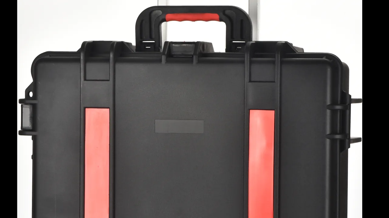
The moment a busbar trunking run leaves the factory, with copper bars cut and plated and insulator supports assembled, it is at its best and at its most fragile. From there it faces warehouse staging, loading, long-haul road or sea freight, repeated transfers, hoisting, open-air staging and finally assembly into a continuous distribution run. What decides whether it passes handover tests first time is rarely the grade of copper. It is whether plating was scratched, whether insulators picked up hairline cracks, and whether long conductors stayed straight.
JUNZHIJIA holds a simple principle: protection for busbar systems cannot be judged by whether the outer case resists compression, because three lines must hold together — plating intact, insulator supports uncracked, and conductor flatness within tolerance. Lose any one and the failure surfaces later as rework during the temperature-rise or insulation test, at many times the cost of the packaging that should have prevented it.
Table of Contents
- Mapping Failure Modes in Busbar Storage and Transit
- Copper Bars: Plating, Oxidation and Flatness
- Insulator Supports: Managing the Brittleness of Epoxy, DMC and Polyester
- Joints, Expansion Sections and Tap-Off Units
- Aluminium Bars and Copper-Aluminium Transitions: The Silent Corrosion Path
- Segmentation and Packing-Unit Planning
- Sealing, Moisture Control and Pressure Equalization
- Cushion Liners and Compartments: EPE, EVA, IXPE and XPE
- Supporting Long Sections Against Bending
- Vibration, Shock and Stacking Verification
- Temperature, Humidity, Salt Spray and Plating Protection
- Incoming Acceptance Criteria and Unpacking Re-Inspection
- Selection Table, Customisation Flow and OEM/ODM
- Frequently Asked Questions FAQ
- Conclusion and Related Reading
Mapping Failure Modes in Busbar Storage and Transit
A low-voltage, densely insulated busbar run is three things stacked together: current-carrying copper or aluminium bars, the supports that locate and insulate them (cast epoxy blocks, DMC moulded clamps, insulators or barriers), and a metal enclosure. Each layer is sensitive to a different transport condition, so one specification number cannot cover them all.
Copper bars fear surface condition. Performance depends on a smooth, clean, flat lap face, and once it carries a scratch, an oxide film or a compression mark, contact resistance rises and local heating follows. Insulator supports fear stress concentration. Epoxy and DMC are hard but brittle, strong in compression yet notch-sensitive, so a loaded sharp corner can start a through-crack barely visible to the eye. Enclosures fear long-span stiffness. A standard section can be three or six metres long and its mid-span deflects under self-weight and stack load, so once the enclosure shifts relative to the conductors inside, the insulators become victims rather than protected parts.
| Failure mode | Main trigger | On-site consequence | Packaging countermeasure |
|---|---|---|---|
| --- | --- | --- | --- |
| Plating scratched | Direct rubbing, trapped debris | Local oxidation, higher contact resistance | Acid-free wrap, form-cut compartments, no bare stacking |
| Bars bent or twisted | Mid-span loading, rough hoisting | Flatness out of tolerance, misalignment | Multi-point supports, overhang limits, cradles |
| Insulators cracked | Sharp-corner loading, stacking, drop shock | Lower insulation resistance, flashover | One part per pocket, no nesting, radiused pads |
| Lap faces contaminated | Dust, sweat, moisture, oil | Contact resistance rise, temperature-rise failure | Peelable film, bagged joints, desiccant |
| Bolts and disc springs lost | Loose accessory packing | Site work stops for missing parts | Dedicated compartments, packing list check |
| Enclosure deformed | Over-stacking, forklift impact | Reduced ingress protection, rework | Stack-limit marking, ribs, corner protectors |
The design rule follows: allocate protection by component, not by whole assembly. The conductor layer is about isolation and cleanliness, the insulation layer about stress and shock, and the enclosure layer about support and stacking. The three countermeasure sets hardly overlap.
Copper Bars: Plating, Oxidation and Flatness
Copper bars are the value centre of a busbar system and the parts most easily ruined by surface damage. Hard-drawn copper has excellent conductivity but forms a cuprous oxide film quickly in air. To suppress oxidation and stabilise contact resistance, conductors are normally tin-plated, silver-plated where lower resistance is needed, and sometimes nickel-plated. That coating is only tens of microns thick, a scale that makes it highly sensitive to abrasion.
The first risk is plating scratch. When two bare bars are stacked directly, vibration drives small relative movement and the plating wears through until base copper shows. Exposed copper oxidises in damp air, resistance climbs, and heat concentrates at the joint in a loop of rising temperature and faster oxidation. Bars must therefore stay face to face without direct contact: an acid-free or neutral paper layer between them, and foam or soft corner blocks at the ends.
The second risk is oxidation and sulphidation. Even tin can darken as a sulphide film forms if the packaging environment contains sulphur or stays humid. Sulphide layers are high-resistance films and degrade a lap joint badly. For long sea voyages or humid projects, the case should carry vapour-phase corrosion inhibitor (VCI) material and silica gel desiccant, with a humidity indicator card so the internal microclimate becomes traceable data.
The third risk is flatness. Conductors hold very small deviation from straight, with roughly two millimetres per metre a common control target. The greatest enemy in transit is not a shock but a sustained self-weight bending moment. A six-metre bar simply supported at both ends with an unsupported middle sags slowly into plastic deformation that cannot be recovered. Support spacing for long sections must therefore be far tighter than for short parts.
| Surface finish | Typical thickness | Protection goal | Degradation in transit |
|---|---|---|---|
| --- | --- | --- | --- |
| Bare copper | None | Short-term containment only | Oxidation, sulphidation, scratching |
| Tin plating | Roughly 8 to 20 microns | Oxidation resistance, stable resistance | Worn by rubbing, scratched |
| Silver plating | Roughly 5 to 12 microns | Lowest contact resistance | Sulphide blackening, scratching |
| Nickel plating | Roughly 5 to 15 microns | Wear and corrosion resistance | Brittle flaking |
Thicker plating is not automatically better, but transport protection is always better with more isolation. Preventing relative movement preserves the factory condition more reliably than polishing afterwards.
Insulator Supports: Managing the Brittleness of Epoxy, DMC and Polyester
Insulator supports hold live conductors at an exact position and provide insulation distance between conductor and enclosure. Three material families dominate: cast epoxy, DMC/BMC polyester moulding compound, and injection-moulded PA66 or PC. All are hard, and the other side of hard is brittle.
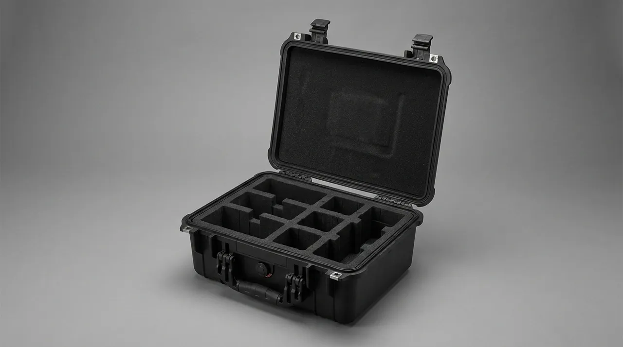
Cast epoxy parts are moulded as one body of resin and filler. Strength and dielectric performance are excellent, but the cured network has almost no plastic capacity, so its response to force is binary: unchanged or cracked. Epoxy cracks often start at internal filler particles or voids, and the propagation path is hidden, so the eye sees a hairline while insulation resistance has already dropped.
DMC/BMC parts are compression-moulded from a dough containing glass fibre and mineral filler. They are slightly tougher than pure epoxy, but the fibre-resin interface at edges and bolt holes is a natural weak point. Under local compression, fibre and resin separate to create internal voids, which become initiation sites for partial discharge.
PA66 and PC mouldings are the toughest of the three and tolerate some elastic deformation, but they absorb moisture and change dimension, and under sustained load they creep and relax, letting conductor position drift.
| Material | Strength character | Main weakness | Packaging focus |
|---|---|---|---|
| --- | --- | --- | --- |
| Cast epoxy | High strength, rigid | Brittle, notch-sensitive | Separate pockets, radiused pads, no nesting |
| DMC/BMC moulding | Medium-high strength | Fibre interface at holes and edges | Protect holes, avoid point loads |
| PA66 moulding | Good toughness | Moisture swelling, creep | Moisture control, no sustained compression |
| PC moulding | Good impact resistance | Stress cracking | Keep away from oils and solvents |
In packaging the rule is one sentence: no two insulator parts may be stacked directly, and no insulator may serve as a load-bearing spacer. Use a form-cut pocket in EVA or XPE, each part sitting in a cavity slightly larger than itself with two or three millimetres of wall clearance. For insulators with sheds or bosses, cut the pocket to the largest outline so the part is never supported only at a protruding boss, which turns contact into a point load. A common error is the convenient drop-in: pushing insulators into gaps between copper bars to save space, after which stack load makes the insulator carry the whole force and a batch arrives cracked.
Joints, Expansion Sections and Tap-Off Units
A busbar system is assembled from straight runs, bends, tees, offsets, start units and tap-off branches. Sections meet at joints, and joints demand the highest standards of cleanliness and flatness in the whole assembly.
The heart of a joint is the lap face, where two conductors are clamped by bolts to pass current. Contact resistance there depends on roughness, cleanliness and torque, so before assembly it must be scratch-free, oxide-free and oil-free. Transit threatens it three ways: lap faces rubbing against each other or the enclosure, dust settling on them, and local corrosion from sweat or rain. Apply a peelable protective film to finished lap faces, or wrap whole sections in acid-free paper. Joint hardware — bolts, disc springs, washers, shrouds — goes into its own compartment, which protects it from knocks and lets crews count it section by section.
Expansion sections are the other sensitive item. They absorb length change from load heating or building settlement through controlled flexible deformation, using corrugated bellows, flexible braid or sliding elements. An expansion section must be secured in transit at its natural length: not compressed, not stretched, and above all not bent. Once a bellows is crushed, its compensation capacity is permanently lost and no on-site tightening restores it. Pack them one per compartment, held at both ends by locating blocks.
| Component | Transit sensitivity | Typical damage | Protection |
|---|---|---|---|
| --- | --- | --- | --- |
| Joint lap face | Cleanliness, flatness | Scratches, contamination, oxidation | Peelable film, acid-free wrap, separate bag |
| Joint bolts and springs | Loss, corrosion | Missing parts, wrong torque | Small compartments, desiccant, kitted per section |
| Expansion section | Length, bellows form | Crushed, stretched, bent | Fixed at both ends, one per package |
| Tap-off box interface | Deformed fingers, worn contacts | Poor contact, hard insertion | Form-cut liner, interface caps |
| Insulation shroud | Cracking, distortion | Insulation failure | Managed with insulators, no stacking |
Joint quality decides whether a run passes its temperature-rise test, so give the joint a compartment of its own rather than burying it among long conductors to save volume.
Aluminium Bars and Copper-Aluminium Transitions: The Silent Corrosion Path
To cut weight and cost, many runs use aluminium bars, or a transition joint between copper and aluminium sections. The two metals sit at different electrode potentials, so once both are exposed to an electrolyte film they form a galvanic cell: aluminium dissolves preferentially as the anode, corrosion products pile up at the interface, and contact resistance climbs. The process is silent, showing only as a dull or whitish surface while the conductive path deteriorates.
Three conditions trigger it: water, an electrolyte such as salt or alkaline residue, and direct metallic contact between the two metals. All three appear together in transport and staging — salt-laden coastal air, condensation inside a container as temperatures swing, and construction dust absorbing moisture into a liquid film.
| Condition | Source | Mechanism | Countermeasure |
|---|---|---|---|
| --- | --- | --- | --- |
| Liquid water film | Condensation, rain, washdown | Ion migration path | Sealed chamber, breather valve, desiccant |
| Electrolyte | Salt spray, dust, hand sweat | Raises conductivity | VCI material, neutral interleaving paper, wipe on arrival |
| Direct copper-aluminium contact | Transition joint design | Galvanic cell, aluminium dissolves | Rely on the tin or silver barrier |
| Thermal breathing | Day and night cycling | Repeatedly draws in humid air | Control when the case is opened |
At a transition, factories rely on a tin or silver layer as the barrier between the two metals. That barrier is thin, so transport protection means keeping it unbroken while holding internal humidity below the dew point. On humid or coastal projects, a humidity indicator card plus an adequate desiccant charge, read before the case is opened, is the most cost-effective judgment tool available.
Segmentation and Packing-Unit Planning
A busbar run is rarely shipped as a complete line. It is broken into functional sections and grouped into packing units, and how those units are drawn decides both protection difficulty and site assembly efficiency.
Long straight sections run from three to six metres and are the long-span, high-mass items; no standard case solves their mid-span sag, so they need a timber or metal cradle working with end-holding features. Bends, tees and offsets are irregular, bulky but shorter, and suit a case with a form-cut liner. Tap-off boxes, start units and accessories are small, valuable and easily lost, so they suit compartmentalised totes or smaller cases carried together.
| Packing unit | Size profile | Protection difficulty | Recommended approach |
|---|---|---|---|
| --- | --- | --- | --- |
| Long straight section | 3 to 6 m, slender | Mid-span sag, plating rubbing | Multi-point cradle, form-cut end restraints |
| Bend, tee, offset | Irregular, large | Complex outline, impact damage | Form-cut liner case, corner protectors |
| Tap-off or start unit | Medium-small, high value | Fragile interfaces, easily lost | Compartment tote, interface caps |
| Joints and accessories | Small, many variants | Mixed lots, missing parts | Dedicated compartments, packing list |
| Insulator supports | Small, brittle | Cracking, crushing by nesting | One part per form-cut pocket |
One discipline is often missed: never mix heavy parts with brittle parts in the same compartment. Dropping insulator supports and joint bolts into one pocket, or letting a tap-off box press on an insulator, is the leading cause of batch cracking on arrival. Each compartment should carry one protection task, and the inside of the lid should hold a table linking section number, contents and quantity so the site can check against the drawings the moment the case opens.
Sealing, Moisture Control and Pressure Equalization
A busbar enclosure has some protective capability of its own, but internal packaging of conductors and insulators usually relies on a dedicated case or moisture barrier. The goal is to hold the microclimate below the design humidity rather than simply to keep rain out.
Ingress definitions follow the IEC 60529 and GB/T 4208 grading method: IP65 means dust-tight and protected against water jets from any direction, while IP67 adds short immersion protection. For most indoor projects an IP65 case is sufficient; only coastal, chemical or long-term open-air storage projects justify IP67. The better the seal, however, the more closed the case, and the larger the pressure differential created by day and night temperature swings. Without a balancing feature, that differential keeps squeezing the gasket and accelerates aging, and at the moment of opening it pulls damp outside air into the case.
The standard answer is a hydrophobic breather valve, as described in Pressure Equalization Valve Selection for Protective Cases, which lets gas equalise slowly while a hydrophobic membrane blocks liquid water. On gasket material, see Protective Case Seal Materials; for moisture-sensitive busbar parts, EPDM is usually preferred for its weathering and low vapour permeation.
| Countermeasure | Function | Where it fits | Watch point |
|---|---|---|---|
| --- | --- | --- | --- |
| Perimeter gasket | Blocks liquid water and dust | Every sealed case | Keep compression in the design band |
| Breather valve | Balances internal and external pressure | Large temperature spans | Check the membrane for clogging |
| Silica gel desiccant | Absorbs residual internal moisture | Sea freight, humid climate | Size by volume and duration |
| Humidity indicator card | Records the microclimate | Full traceability | Read before opening on arrival |
| VCI vapour inhibitor | Suppresses metal oxidation | Where bare metal remains | Never co-packed with foodstuffs |
Remember that desiccant only absorbs the moisture sealed in with the goods; it cannot fight a continuous leak. If gasket compression is short or the case is cracked, the desiccant saturates and stops working. Moisture control runs in one order only: seal first, dry second.
Cushion Liners and Compartments: EPE, EVA, IXPE and XPE
Busbar components vary enormously in shape: slender copper bars, flat enclosure panels, solid insulator blocks, insulators with protruding bosses. No single material delivers both location and energy absorption, so liners are built in layers.
| Foam material | Density and feel | Key behaviour | Best-suited parts |
|---|---|---|---|
| --- | --- | --- | --- |
| EVA | Medium-high density, firm | Dimensionally stable, precision cuttable | Compartment skeleton, insulator pockets |
| EPE | Low density, soft | Good compression recovery | Large-part cushion layers, gap filling |
| IXPE | Cross-linked, medium density | High closed-cell ratio, moisture barrier | Contact layer against conductors |
| XPE | Chemically cross-linked | Uniform cells, moderate cost | Broad liners, case wall lining |
| Rigid PE foam | High density, stiff | Strong load bearing | Base load layer, stacking support blocks |
The usual combination is EVA for the skeleton, EPE for cushioning and IXPE as the moisture barrier. EVA is CNC-cut to trap each part at its design position, EPE fills gaps and absorbs impact energy, and IXPE sits against copper bars and insulators as a layer resisting both moisture and scuffing. This layered build beats a single high-density foam in drop and vibration testing because it divides location and energy absorption between two materials. For a broader comparison, see Internal Foam Types for Protective Cases.
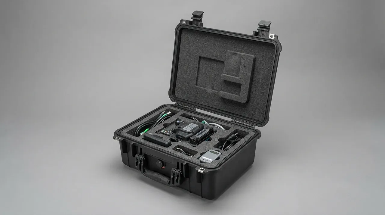
Compartment design must also allow hand clearance. If adjacent pockets touch, a gloved finger cannot enter and crews pry components out by the edge, damaging insulator corners first. A ten to fifteen millimetre notch or radiused chamfer on each wall solves this. For insulator supports, the pocket floor should be flat or a large-radius arc, never a shape that supports the part only at a boss.
Supporting Long Sections Against Bending
Long straight sections are the hardest items in a busbar shipment. Their failure mode is not a break but a slow bend. A six-metre conductor simply supported at both ends with an unsupported middle accumulates mid-span deflection under self-weight, stack load and vibration, and once it passes the elastic limit the deformation becomes plastic and cannot be straightened on site.
The controlling parameters are support spacing and end overhang. Accepted practice keeps support points no more than roughly 1.2 metres apart with end overhang no more than about 300 millimetres; for larger, heavier sections, spacing tightens further. Supports should land on rigid nodes rather than the thin mid-wall of an enclosure, or the wall is dented locally.
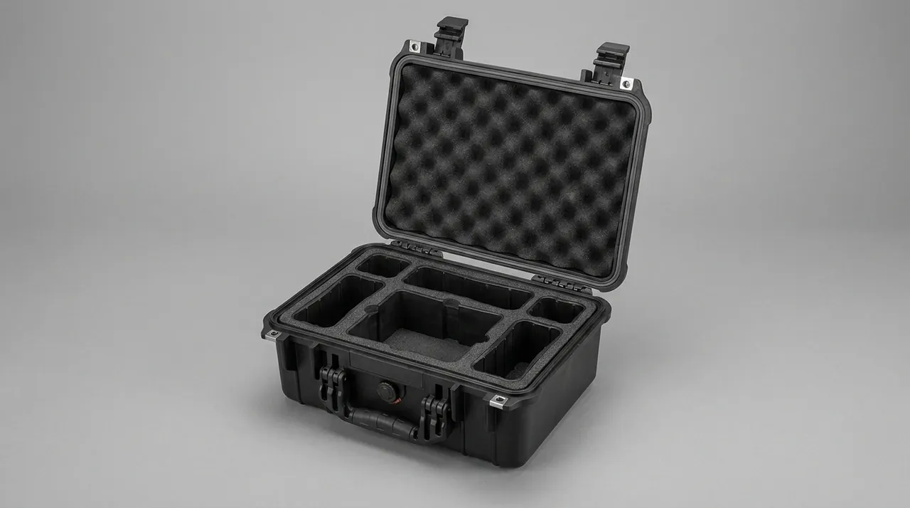
Beyond spacing, three details decide the outcome.
The first is the hardness of the support face. Where a block touches a copper bar, laminate its surface with EPE or felt to spread the contact area and protect plating. A hard, roughly machined support point becomes an abrasive pad under vibration.
The second is the restraint method. Allow a small sliding clearance along the length to release thermal contraction stress, while locating the section positively in the lateral direction to prevent rolling or tipping. Clamping both ends rigidly generates axial stress as temperature changes and deforms the ends.
The third is the stacking posture. Stack face to face, not edge to edge, so the broad face carries load rather than one edge. Intermediate tiers must never bridge an unsupported gap; a separator spreads the load across several support points.
| Control parameter | Recommended range | Consequence of failure | Check method |
|---|---|---|---|
| --- | --- | --- | --- |
| Support spacing | No more than about 1.2 m | Mid-span sag, plastic bending | Measure flatness on arrival |
| End overhang | No more than about 300 mm | Drooping, deformed ends | Visual check with a straightedge |
| Lateral location | No sideways movement | Rolling, tipping, impact | Check for displacement on opening |
| Inter-tier support | Face contact, no bridging | Crushed middle tier, dented enclosure | Inspect tier by tier |
| Contact facing | EPE or felt | Plating abrasion | Visual check of plating |
Packaging a long section is a structural engineering problem, not a materials problem. The right foam only prevents impact damage; only correct spacing, overhang and restraint prevent bending.
Vibration, Shock and Stacking Verification
Verification means reproducing rough handling in the laboratory: random vibration, controlled drop, constant-load stacking and thermal cycling, drawn from families such as the GB/T 4857 transport package series, the ISTA procedures, and ASTM D4169 distribution cycle testing.
| Test | Reference method family | Busbar relevance |
|---|---|---|
| --- | --- | --- |
| Random vibration | Transport vibration testing | Plating rubbing, bolt loosening, support fatigue |
| Controlled drop | Drop graded by weight | Dropped during handling, forklift impact |
| Constant-load stacking | Compression hold test | Multi-tier storage, container stacking |
| Thermal and humidity cycling | Alternating high and low temperature | Condensation, gasket recovery, dimensional change |
| Seal check | Leakage and pressure decay | Gasket and breather valve effectiveness |
| Neutral salt spray | GB/T 10125 | Plating durability in coastal and chemical sites |
For busbar systems, random vibration cannot be skipped. Its damage mechanism is not a single break but wear and loosening from sustained micro-movement: where conductors, or a conductor and a support, have slight relative displacement, plating is polished into bright marks within hours, and joint bolts can back off slowly under the spectrum. Post-vibration inspection should focus on plating surfaces, bolt preload and any new insulator cracks. For test design thinking, see Transport Vibration Testing for Protective Cases.
Stacking tests must record deflection under load and residual deformation after unloading. For long-part cases, also check whether inter-tier supports crushed plastically. A workable criterion: residual deformation must not prevent continued stacked service, and no internal part may show new deformation or cracking.
Temperature, Humidity, Salt Spray and Plating Protection
Busbar storage and transport cross several climates. A good scheme isolates environmental swings outside the case; a poor one lets the interior condense repeatedly.
The neutral salt spray test to GB/T 10125 is a standard way to rank plating durability, but it produces a relative ranking between processes only: it cannot be converted directly into field service life, and it does not support any certification claim. That limitation belongs in the acceptance clauses.
| Environmental factor | Effect on busbar parts | Protection focus |
|---|---|---|
| --- | --- | --- |
| High humidity | Conductor oxidation, insulation leakage | Desiccant, sealing, indicator card |
| Temperature swing | Internal condensation, pressure breathing | Breather valve, controlled opening |
| Salt spray | Plating corrosion, galvanic attack | Weathering seals, VCI, wipe on arrival |
| Dust | High-resistance layer on lap faces | Keep closed, open in a clean area |
| Ultraviolet light | Plastic enclosures and labels degrade | UV-resistant material, shaded staging |
A practical acceptance rule reads: when the humidity indicator card exceeds its set limit, treat the inner packaging as failed, arrange drying before opening and record the evidence. Binding microclimate data to transport events is what allows responsibility to be reconstructed later.
Incoming Acceptance Criteria and Unpacking Re-Inspection
Incoming re-inspection should replace "it looks fine" with quantifiable criteria wherever possible. Confirm the ranges below against the drawing and technical agreement.
| Check item | Reference criterion | Method | Action if failed |
|---|---|---|---|
| --- | --- | --- | --- |
| Conductor flatness | Within about 2 mm per metre | Straightedge or string line | Record, assess straightening |
| Plating condition | No exposed copper, no through-scratch | Visual plus reference photographs | Local repair or replace section |
| Insulator appearance | No cracks, no chipped corners | Visual plus magnifier | Replace, never use a repaired part |
| Insulation resistance | Not below the agreement value | Insulation resistance meter | Dry and retest |
| Lap face cleanliness | No oil, dust or oxidation | Visual plus wipe test | Clean and re-protect |
| Joint hardware | Matches the packing list | Check against the list | Reissue parts, no substitutions |
| Internal humidity | Indicator card below its limit | Read before opening | Record, arrange drying |
The key is the evidence chain: photograph the case exterior and the humidity indicator reading before opening, then photograph conductor surfaces and insulators section by section, and compare with pre-loading images. That draws a clean line between damage in transit and damage during loading.
Selection Table, Customisation Flow and OEM/ODM
The table below consolidates the analysis into a working reference for engineering and procurement.
| Scenario | Primary protection goal | Recommended case and liner | Suggested class |
|---|---|---|---|
| --- | --- | --- | --- |
| Densely insulated straight run | Flatness, plating | Multi-point cradle, EVA end forms | Set by transport exposure |
| Air-insulated bend section | Enclosure distortion, insulator cracking | Form-cut liner case, corner protectors | IP65 |
| Tap-off boxes and accessories | Interface protection, loss prevention | Small-part compartment tote | IP65 |
| Insulator supports shipped alone | Crack prevention | One part per form-cut EVA pocket | IP65 |
| Indoor project, short haul | Dust and knocks | Standard protective case | IP54 to IP65 |
| Coastal or chemical project | Salt spray, galvanic attack | Sealed case, VCI, desiccant | IP66 to IP67 |
| Long-term open-air staging | Rain, condensation | Sealed case, breather valve, shade | IP66 to IP67 |
| Export sea freight | Long-duration humidity | Sealed case, desiccant, humidity card | IP67 |
One discipline bears repeating: the equipment protection class and the packaging protection class are two separate specifications. A section finally installed indoors may still need IP67 packaging, because the packaging faces a harsher multi-modal journey. Put a coastal-project part into a splash-resistant box and it has taken on water before reaching site.
A typical customisation flow runs from drawings and a component list, through packing-unit and liner definition, sample validation and trial packing, to volume production. Where tooling is involved, mould ownership and intellectual property clauses are settled first; where supply is long term, liner materials, seal specification and inspection criteria belong in the technical agreement.
Frequently Asked Questions FAQ
Q: Why can a busbar run not simply be shipped in a wooden crate with stretch wrap?
A: A crate and stretch wrap solve outer containment and rain shedding, but they do not address relative friction between conductors, mid-span bending of long sections, or stress concentration in brittle insulators. Plating is only tens of microns thick, and vibration inside a crate keeps adjacent conductors, or a conductor and a timber bearer, moving slightly against each other, so the coating wears away and base copper oxidises, raising contact resistance at the joints. At the same time a long conductor fixed at both ends with an unsupported middle accumulates plastic deformation from self-weight and stack load, and once flatness is out of tolerance the sections will not align on site. Insulators, meanwhile, are the parts most likely to take a point load from a loose fitting, and a hairline crack found after arrival cannot be repaired in the field. The correct approach adds a support cradle, a form-cut liner and a conductor interleaving layer inside the crate, so that rain protection, internal location and contact isolation all exist together rather than relying on the crate shell alone.
Q: What most easily damages the tin plating on copper bars in transit?
A: Friction wear is the leading cause, with chemical attack second. Friction wear comes from slight relative movement between conductors, or between a conductor and the enclosure or a support block, and transport vibration amplifies that movement into continuous abrasion that eventually rubs through the coating. Chemical attack comes from sulphur-bearing air, hand sweat, oil and moisture-laden dust residues, which form dark sulphide films or corrosion pits on the plated surface and raise contact resistance. Transport protection therefore centres on isolating relative movement and controlling microclimate humidity: interleave conductors with acid-free paper or PE film, restrain the ends with soft blocks, and fit the case with VCI material, silica gel desiccant and a humidity indicator card. Note that the plating thickness is not the decisive variable. A thick coating that is abraded through fails in exactly the same way as a thin one, so in transit the discipline of keeping faces out of direct contact is always more effective than polishing damaged surfaces later.
Q: How does the packaging emphasis differ between cast epoxy and DMC insulators?
A: Both are hard and brittle, but the weak mechanism differs. Cast epoxy is a homogeneous cross-linked body with almost no plastic capacity, so it is extremely sensitive to notches and sharp corners; a loaded edge can crack in one event, and the crack may start at an internal filler interface, leaving only a hairline on the outside while dielectric performance has already fallen. DMC and BMC parts contain substantial glass fibre and mineral filler, so the bulk is slightly tougher, but the fibre-resin interface at edges and bolt holes is a natural weak point, and local point loading causes fibre debonding and internal voids that become partial-discharge sites. Epoxy parts therefore need large-radius pads, no point loads and no nested stacking, while DMC parts need protected holes and edges with local pressure avoided. In both cases mark orientation and load-bearing faces on the packing list, so that nobody stores the case inverted or uses an insulator as a spacer between heavier components.
Q: How are busbar joint lap faces kept clean and flat during transport?
A: Three things must be done. First, isolate: apply a peelable protective film to finished lap faces, or wrap the whole section in acid-free paper before packing, so faces never rub directly against each other. Second, separate the hardware: put joint bolts, disc springs, washers and insulation shrouds into dedicated small compartments, which prevents loss and keeps metal parts from colliding with large components. Third, control humidity: lap faces are highly sensitive to moisture, so the case should carry desiccant and a humidity indicator card, read before opening on arrival. Once opened, inspect for oil, dust and oxidation colour, and clean and re-protect before assembly. Contact resistance depends directly on surface roughness, and scratches caused in transit usually cannot be fully removed by polishing on site, which is why protection has to be completed at the packing stage rather than at receiving. A joint that looks acceptable can still fail a temperature-rise test later. Keep the wrapping in place until the moment of assembly.
Q: How should a six-metre busbar straight section be supported?
A: Treat it as a beam rather than as a packaged item. Support spacing should generally stay within about 1.2 metres and end overhang within about 300 millimetres, tightened further for large-section, heavy densely insulated runs. Supports should sit on rigid nodes rather than the thin mid-wall of the enclosure, where they would dent the surface, and the support face should be laminated with EPE or felt to spread contact area and protect the plating. For restraint, allow a small sliding clearance along the length so thermal contraction stress can release, while positively locating the section laterally to prevent rolling or tipping. Stack face to face rather than edge to edge, never bridge an unsupported gap in an intermediate tier, and add a separator where needed to spread load across several support points. These values belong in the packing drawing and in the technical agreement, not in an improvised decision made on the loading dock. Record them so every shipment repeats the same setup.
Q: Does a busbar case need to be rated IP67?
A: Not necessarily; it depends on the harshest environment across the whole lifecycle. The first digit of an IP code covers solids and the second covers water: IP65 means dust-tight and resistant to water jets, while IP67 adds short-term immersion protection. For indoor projects, short hauls and shaded staging, IP65 is normally sufficient. IP67 is genuinely justified for coastal high-salt projects, chemical plants, long-term open-air storage and long-duration export sea freight. Note that a better seal means a more closed case and a larger pressure differential from day and night temperature swings, so a breather valve must be fitted, or the gasket is held under continuous compression and ages faster while opening the case pulls damp air inward. The correct order is to define the environment first, then the class, then verify the breather and desiccant allowance against the longest journey the system will actually make. Where the route or the season changes, revisit the class before the next batch ships.
Q: Why do copper-aluminium transitions corrode so easily, and how is that prevented?
A: Because copper and aluminium sit at different electrode potentials. When both are exposed to an electrolyte film they form a galvanic cell, aluminium dissolves preferentially as the anode, and corrosion products accumulate at the interface and push contact resistance upward. The trigger is the combination of water, an electrolyte and direct metallic contact, and transport and staging readily supply all three: salt spray in coastal air, condensation inside a container as temperatures swing, and construction dust absorbing moisture into a film. Protection really means keeping the factory-applied tin or silver barrier unbroken while holding internal humidity below the dew point. In practice that means locating the transition so it cannot rub against hard parts, fitting VCI material and an adequate desiccant charge, using a humidity indicator card as an arrival criterion, and reading the card before opening so the surface can be given a neutral wipe-down. Because the corrosion is silent, surface inspection alone is not enough. Ask the supplier for the barrier specification and check it against the drawing.
Q: Which quantified indicators should an incoming busbar inspection check?
A: Six groups, always confirmed against the technical agreement. First, conductor flatness, commonly controlled to about two millimetres per metre and measured with a straightedge or string line. Second, plating condition, checked for exposed copper and through-scratches, ideally against reference photographs. Third, insulator appearance, checked for cracks and chipped corners with a magnifier, with any cracked part replaced rather than repaired. Fourth, insulation resistance, measured with an insulation resistance meter and compared with the specified value, drying first if moisture is suspected. Fifth, lap face cleanliness, confirming no oil, dust or oxidation colour. Sixth, joint hardware quantity and specification against the packing list. Read the internal humidity indicator card and photograph it before opening, then photograph each section after opening, so the loading, arrival and unpacking record forms one complete evidence chain. Without that chain, a genuine transit defect can easily be mistaken for a loading error.
Conclusion and Related Reading
Protecting a busbar run is a job of state preservation: deliver the plating, flatness and insulators to site exactly as they left the factory. JUNZHIJIA builds form-cut liners, section cradles, breather valves and OEM/ODM tooling for busbar cases.
Related Reading