

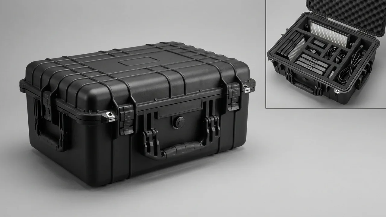
Two numbers usually decide whether a carbon fiber line case has done its job: the runout of the rollers after arrival, and the survival rate of the high-temperature furnace parts. A carbon fiber line is a continuous process, running from precursor through pre-oxidation, carbonisation, surface treatment and sizing, and dozens of guide and transport rollers tie the sections together. These rollers have high length-to-diameter ratios, fine surface finish requirements and tight tolerances at the journal and bearing seats. Choose the wrong support position or lose the horizontal restraint, and self-weight deflection combines with road vibration to leave surface marks, bent journals and out-of-tolerance runout. Parts for the pre-oxidation and carbonisation furnaces carry a completely different risk profile: graphite heating elements, rigid carbon felt and ceramic components are brittle and shock sensitive, while conductive carbon dust threatens anything electrical. A carbon fiber equipment case therefore has to solve long-part support and brittle-part isolation inside one packing system.
This article is written for equipment and process engineering teams at carbon fiber and composite producers, line integrators and spare parts distributors. It covers roller support and locking, surface protection criteria, bearing housings and drive components, the brittleness and dust issues of pre-oxidation and carbonisation parts, inert gas piping, tension and electrical components, load calculation and lifting for long cases, moisture protection on ocean voyages, and acceptance testing, closing with a selection matrix, cost structure, FAQs and further reading.
Contents
- Where the parts sit in the line and what threatens them
- Rollers: length ratio and deflection together
- Surface protection: coatings, mirror finish and scratch criteria
- Support and locking structures for roller cases
- Bearing housings, drive shafts and couplings
- Pre-oxidation furnace parts: hot panels and ducting
- Carbonisation and graphite parts: brittle, dusty, conductive
- Inert gas piping and sealing components
- Tension and electrical items: sensors, encoders, drives
- Load calculation and lifting for long cases
- Moisture and oxidation control on long voyages
- Test items and arrival acceptance
- Scheme selection and cost build-up
- Customisation workflow and delivery requirements
- Frequently Asked Questions
- Conclusion and related reading
Where the parts sit in the line and what threatens them
A typical carbon fiber line comprises precursor handling, a pre-oxidation oven, low-temperature and high-temperature carbonisation furnaces, surface treatment and sizing, then drying and winding. Between these sections sit large numbers of guide rollers, tension rollers and turning rollers. Their share of total line value is small, yet they set fibre path and tension uniformity. A single roller with excessive runout leaves a periodic mark on the tow, which then shows up as strength scatter in the finished fibre.
Transport risk falls into three shapes. Long rotating parts include rollers, roller cores and drive shafts, where stiffness is governed by the length-to-diameter ratio and poor support immediately produces deflection and surface marking. Brittle high-temperature parts include graphite electrodes, graphite heating elements, rigid carbon felt assemblies, ceramic rollers and ceramic insulators. They absorb almost no impact energy, so exceeding the strength limit means brittle fracture, usually starting at a corner, a hole or a thread. Precision electrical and measuring items include tension sensors, encoders, servo motors and variable frequency drives, which tolerate little shock and dislike moisture and conductive dust.
The three groups pull the case design in different directions. Long parts need deflection suppressed, brittle parts need shock isolated, electrical parts need moisture and dust excluded. Loading all three into one cavity means one group is always compromised. Zoning by component shape at design stage is far more effective than zoning by process section at packing time.
| Group | Typical parts | Main failure mode | Packing strategy |
|---|---|---|---|
| --- | --- | --- | --- |
| Long rotating parts | Guide rollers, tension rollers, cores, drive shafts | Self-weight deflection, surface marks, bent journals | Multi-point cradles plus horizontal locking, never hang from one point |
| Brittle hot parts | Graphite heating elements, rigid carbon felt, ceramic rollers | Chipped corners, cracked holes | Individual cavities with soft facing, limit acceleration |
| Sealing and piping | Graphite seal rings, flexible hoses, flanges | Ring ovality, deformed ports | Ring cradles, end guards, separate cells |
| Electrical and measuring | Tension sensors, encoders, servo motors | Loaded diaphragms, corroded shafts, loose wiring | One cavity per unit, shaft caps, dehumidified packing |
| Surface treatment parts | Treatment bath components, sizing rollers | Distorted walls, scratched roller surface | Internal bracing, surface sleeves |
| Insulation and thermal parts | Insulation modules, thermal shields | Moisture degradation, damaged edges | Moisture-proof packing, reinforced edges |
Rollers: length ratio and deflection together
A roller in transit is a simply supported beam. Mid-span deflection under uniformly distributed self-weight varies with the fourth power of support spacing and inversely with section inertia. Double the unsupported span and mid-span deflection rises by a factor of sixteen. For a roller with a length-to-diameter ratio above 20, even a modest mass can exceed the permitted deflection when the only supports sit at the two ends, and the deformation may not fully recover.
Three measures belong together. First, increase the number of supports. Three or four cradles positioned at the journals and along the barrel are appropriate for long rollers, with a soft covering at each contact to spread stress and prevent local flattening. Second, shorten the free span. Where a mid-length support is structurally impossible, fit a support beam inside the case to break a long span into several short ones, with the beam itself deflecting no more than one fifth of the roller's allowable deflection. Third, never let the journal carry the whole load. The journal and bearing seat are the tightest-tolerance surfaces on the part; concentrating load there leaves witness marks at best and bends the journal at worst, and a bent journal makes runout impossible to correct at assembly.
Temperature deserves a mention because it is routinely forgotten. Rollers and case materials expand at different rates, so a long part moved from a cold container into a warm shop changes dimension, and a runout reading taken immediately will be larger than the true value. Let the roller stabilise until the surface-to-ambient difference is within the agreed band, and note ambient temperature alongside the measurement.
Surface protection: coatings, mirror finish and scratch criteria
The roller surface is the hardest part of the component to repair. Once a chrome layer, a ceramic coating or a mirror-finished stainless surface is scratched, local repair rarely restores the original roughness, and regrinding with replating approaches the cost of a new roller. Surface protection therefore belongs in the design specification, not in a decision made on the packing floor.
Three scratch mechanisms. Direct contact damage occurs when the liner contains hard particles or when the surface touches case hardware, bolts or slings. Relative movement damage occurs when initial contact is good but vibration lets the roller slide slightly in its cavity, dragging fine axial marks across the surface. Trapped debris damage occurs when metal chips, grit or tape fragments left during packing are pressed between surface and liner and form point indentations under vibration.
Protection layers. A three-layer approach works: soft covering against the surface, rigid isolation outside it, and dedicated protection for the ends. The soft layer contacts the roller and should be soft, free of hard fillers and non-shedding, with thickness chosen from roller mass and contact width, typically 3 to 8 mm. The rigid isolation layer stops external parts or hardware from bearing on the surface. End protection covers threads and keyways at the journals and shaft ends against impact and corrosion.
Making the criterion measurable. Write surface acceptance into the protocol as measurable items: defined inspection zones, defined instruments such as a roughness tester, magnifier or borescope, and defined thresholds. A common approach compares roughness before dispatch with roughness after arrival, with permitted deviation set by the customer's process requirement, reinforced by a geometric rule such as a limit on the length of any continuous axial scratch. Replacing the phrase no obvious scratches with measurable clauses is the single most effective way to reduce acceptance disputes.
Support and locking structures for roller cases
A roller case must hold, lock and release the part, in that order of priority.
Cradle forms. Short rollers suit a die-cut liner with a semi-circular cavity and a soft contact facing. Long rollers suit segmented cradles, each carrying its own share and positionable inside the case. Segmented cradles spread the reaction forces across several locations and allow one case to serve rollers of different lengths. The cradle must sit on continuous support in the base, otherwise it sinks under vibration and the support geometry changes in service.
Locking methods. Once vertical support is right, horizontal movement has to be restrained. Clamp plates tensioned by bolts work well, provided a soft pad sits between plate and roller. Fabric straps looped around the barrel avoid surface damage but stretch over time and need re-tensioning. In both cases the objective is to limit movement, not to clamp hard, particularly at the bearing seats, where excessive clamping force directly affects fit accuracy.
Shaft ends and keyways. Threads, keyways and oil holes are weak points. Fit guards or caps and mark them to prohibit impact. Where a roller contains internal oil or cooling passages, drain and plug the ports before packing so that nothing leaks onto the liner.
Removal sequence. Open in the order of lid, sides, locking elements, clamp plates, and lift the roller out last. Use fabric slings rather than wire rope, positioned symmetrically about the roller centre of gravity to avoid tilt. Where a forklift assists on site, keep tines away from the surface and shaft ends.
Bearing housings, drive shafts and couplings
Bearing housings, drive shafts, couplings and gearbox parts fail differently from rollers; their critical features are fits and oil seals.
Bearing housings. These are relatively stiff bodies whose main transit risk is impact on the mounting face and distortion of the bore. Face the mounting surface inward or upward, cap the bore against ingress, and where several housings travel together, stack them by size with soft dividers between layers. A housing already fitted with bearings should be treated as a precision item, because shock travels through the body into the rolling elements and raceways.
Drive shafts and couplings. Shafts are slender, but unlike rollers they suffer most at the shaft extension and keyway. Support horizontally at several points, cap the extension and protect the keyway. Elastomeric coupling elements should travel separately, uncompressed and free of grease contamination.
Gearbox parts. A gearbox combines mass, oil and a fragile shaft extension. Check that the oil seal faces upward or sideways so that oil does not pool against the lip, cap the extension, and lift only from the housing lifting eyes, never through the extension or output flange. For long-term storage, follow the maker's storage conditions and rotate the input shaft periodically to redistribute the oil film.
Pre-assembled groups. Some customers ship rollers with bearing housings already fitted. Treat the group as one item for cavity design, but keep the support under the housings rather than the roller surface, and ensure no preload path runs through the bearings. Whether to ship pre-assembled depends on site lifting capability, because a heavier single item raises both support and lifting requirements.
For more on long cylindrical parts, conveyor roller component protection sets out graduated guidance on support spacing and cradle types.
Pre-oxidation furnace parts: hot panels and ducting
The pre-oxidation oven runs typically between 200 and 300 C, and its parts are stainless panels, duct assemblies, fan impellers, dampers and insulation modules. Their room-temperature strength is adequate, but they are mostly large thin shells, so the governing risks are buckling distortion and edge damage.
Controlling panel distortion. A large thin panel sags under its own weight, and vibration makes it worse. Standing or leaning panels store them with the face parallel to gravity, avoiding the mid-span sag that appears when a panel lies flat. Where flat storage is unavoidable, use multi-point support or a full backing board, with spacing calculated from thickness and panel size. Soft dividers between panels prevent face-to-face fretting.
Ducts and flange openings. Duct flanges are weak points and should carry a guard ring so that handling cannot crush the opening. Where flow guides or screens are already installed inside a duct, secure them against loosening, because a detached internal part travels along the duct during transport.
Fans and impellers. Impellers are balanced assemblies with thin blade edges. Local deformation after impact destroys the balance. Give each impeller its own cavity with blades unloaded, cap the shaft extension, and for large diameters use a vertical cradle with circumferential support.
Insulation modules. Insulation fears moisture as much as compression. Damp modules lose performance, and fibre-based modules can slump structurally once wet. Seal them with desiccant, limit the load stacked above, and avoid compression that changes density.
Carbonisation and graphite parts: brittle, dusty, conductive
Carbonisation furnaces run above 1000 C, with graphitisation furnaces higher still. Parts for these sections are largely graphite, rigid carbon felt and ceramics, and their protection logic differs entirely from the previous groups.
Brittle fracture. Graphite and ceramics have no plastic range. Once load exceeds the strength limit, fracture is instantaneous, and cracks usually initiate at holes, threads or corners where stress concentrates. Packing design therefore cannot rely on deformation to absorb energy; it has to limit peak acceleration. In practice: establish the permitted acceleration from the maker's fragility figure or a conservative estimate, choose cushion thickness and density from the cushion curve, then verify by drop or shock testing.
Dust and conductivity. Carbon and graphite dust conduct electricity. Reaching an electrical cavity or a terminal block, it can cause short circuits. Graphite and electrical items must be zoned apart with a dust barrier between them. Clean with filtered vacuum equipment rather than by blowing, and for reusable cases prefer replaceable liner modules, so that a contaminated section is swapped rather than scrubbed.
Separating graphite parts. Graphite components should not be stacked directly on each other, since mutual fretting generates dust and wears the edges. Give each part its own cell with soft facing, and plug threads and fits against impact and ingress. Graphite seal rings are thin-walled and should sit in a ring cradle with circumferential support to prevent ovality.
Rigid carbon felt and insulation. These materials are soft and compressible. Compression changes thickness and density distribution, which in turn affects temperature uniformity inside the furnace. Avoid stacking loads on them, and where stacking is necessary use a pallet with a perimeter frame so that the load path bypasses the felt.
Inert gas piping and sealing components
Carbonisation and graphitisation run under nitrogen or argon, so the consignment usually includes stainless piping, flexible hoses, valves, flanges, seal rings and quick couplings.
Piping. Rigid pipe should be fixed at its original bend radius and never forced straight. Guard the ends and bevels, because a deformed bevel has to be re-machined before welding on site. Coil flexible hose and secure it, avoiding small-radius bends that fatigue the liner and avoiding long-term contact with hard objects that abrades the cover.
Valves and couplings. Valves are passage components, so plug every port against ingress. Handwheels and actuators protrude and bend easily, so give them individual cavities with support. Quick coupling sealing faces cannot be restored once damaged and should be treated as precision sealing surfaces with protective caps.
Seals and gaskets. Graphite seal rings, spiral wound gaskets and elastomer O-rings are all sensitive to temperature and moisture. Elastomers take a permanent set if stored damp or compressed, so pack them sealed, flat and unloaded. Spiral wound gaskets suffer if the winding is impacted, so keep them in original packaging. Graphite rings follow the ring cradle approach described earlier.
Cleanliness of the gas path. Internal cleanliness of gas path components affects later operation, because residual oil or particles can disturb atmosphere purity. Clean and plug pipe and valve internals before dispatch, keep case humidity low, and prevent internal corrosion during the voyage.
Tension and electrical items: sensors, encoders, drives
Tension control is central to carbon fiber quality, and tension sensors, encoders, servo motors and drives form that closed loop. These items are small in volume but high in value, and they tolerate transit conditions poorly.
Tension sensors. Whether strain gauge or piezoelectric, a sensor contains a precision elastic element or diaphragm, and overload or shock causes zero drift. Give each sensor its own cavity, keep the load-bearing face free of contact, and coil the cable with a service loop so it is not repeatedly flexed. Never load a sensor in the same cavity as a heavy part, because a shifting heavy item will strike it directly.
Encoders and resolvers. Encoder shafts and code discs are fragile, and shock can degrade accuracy or cause signal jumps. Cap the shaft, fix the body separately, and leave cable slack.
Servo motors and gearmotor assemblies. Cap the shaft extension, orient the cable entry upward or in a non-loading direction, and avoid sustained load at the seal that might cause oil weeping. Where a motor ships assembled to a gearbox, design the cavity for the group and carry the load through the housing.
Drives and control modules. These fear moisture, conductive dust and free-fall drops. Keep the original packaging inside the outer case, or use a clean bag with antistatic shielding, add desiccant, and control relative humidity before closing. Conductive dust from carbon fiber processing raises drive failure rates measurably, so electrical items need a higher isolation standard inside the case than general workshop equipment.

Load calculation and lifting for long cases
Roller cases and panel cases are typically long and heavy, and structural design cannot rely on experience.
Three levels of calculation. First, cradles and support beams are checked for bending stress and deflection under component self-weight plus a dynamic factor. Second, the base and longitudinal beams are checked for local bearing and global bending using support reactions, with particular attention to concentrated tine loads during forklift handling. Third, walls and corner posts are checked for axial stability under stacking. A dynamic factor of 1.5 to 2.0 is customary, adjusted for road conditions and restraint quality.
Lifting long cases. Centre of gravity and lifting point positions must match, otherwise the case tilts visibly as it leaves the ground. Four lifting lugs with a spreader keep the slings near vertical and prevent a bending moment developing along the length. Long cases should carry centre of gravity marks and lifting point identification, with a lifting diagram supplied alongside.
Forklift compatibility. Fork pockets should run through the base, match the site tine dimensions, and be lined with wear plates. Align the tine centreline with the centre of gravity as closely as possible. A long case lifted on two tines develops significant bending between them, so fit reinforced longitudinal beams and confirm performance in a first-article trial rather than assuming it.
Mobility. Cases moved frequently inside a workshop can take castors and a tow point, but castors become the weak load path during stacking and long-distance transport. Make them detachable, removed and packed separately before shipment, so the case carries load through a flat base.
Moisture and oxidation control on long voyages
Not every part in a carbon fiber line is humidity sensitive, but ocean freight treats rollers and electrical items badly.
Corrosion of surfaces and journals. A chrome surface resists corrosion well, but coating breaks, journal fits and shaft threads are vulnerable. Apply a thin anti-corrosion film or tape to exposed metal, and cap the shaft threads. Choose the product to suit the surface coating, because additives in some corrosion inhibitors affect plating or later sizing operations.
Moisture uptake in graphite and felt. Graphite absorbs some moisture and rigid carbon felt absorbs more. Damp insulation loses performance and complicates the initial atmosphere commissioning. Pack sealed with desiccant and dry the parts after arrival where required.
Condensation in electrical items. Condensation inside drives, sensors and encoders is the most common and least noticed ocean-freight failure. Countermeasures include sealing the unit in a clean bag with desiccant, controlling case humidity, fitting pressure equalisation so that the case cannot draw damp air when it cools, and avoiding untreated timber as contact or filler material. Check the humidity indicator before opening on arrival.
Case humidity management. Bring internal relative humidity to 45 to 55 percent before closing, size desiccant from net volume with 30 percent margin, and for voyages over 30 days use a replaceable desiccant cartridge with a humidity recording label. For pressure differential control, see configuring a case pressure equalisation valve.
Test items and arrival acceptance
Verification covers structure, dynamics, environment and cleanliness, with projects, sequence and sampling agreed in the technical protocol.
| Verification group | Test performed | Objective | Pass basis |
|---|---|---|---|
| --- | --- | --- | --- |
| Structure | Stacking | Confirm long cases do not sag under sustained static load | Base deflection within limit, cradles do not shift |
| Structure | Multi-point lifting | Confirm lug layout and long-case stiffness | No visible tilt, no permanent deformation |
| Structure | Forklift handling | Confirm fork pockets and reinforced beams | No base sag, no laminate separation |
| Dynamic | Random vibration | Confirm supports and locks survive long vibration | Displacement 2 mm or less, no rub marks on surface |
| Dynamic | Drop and incline impact | Confirm cushion design for brittle parts | Acceleration within limit, no chipped graphite edges |
| Environment | Temperature and humidity cycling | Confirm corrosion and condensation control | No rust, no free water |
| Environment | Spray as required | Confirm seal integrity | No water ingress |
| Cleanliness | Carbon dust residue | Confirm cleaning and zoning work | No visible carbon dust in electrical cavities |
Selecting the test methods. Method selection for thermal, humidity, vibration and impact conditions can reference MIL-STD-810H, subject to one clarification: the citation is methodological and no military certification or qualification is asserted. Domestic road and rail movements follow the GB/T 4857 series, while export orders are covered by distribution cycle simulation.
The two core acceptance criteria. Use the change in roller radial runout and the peak acceleration record as the primary criteria. Measure runout before dispatch and after arrival at the same sections and with the same support arrangement. Judge acceleration from shock indicator labels together with test data. For brittle items, use a visual criterion of no chipping, no cracks and intact holes, supported by dye penetrant inspection where required.
Scheme selection and cost build-up
Component shape, transport mode, re-use cycles and site conditions drive the choice. The table gives recommended schemes for common combinations.
| Line situation | Fibre and roller profile | Suggested case build | Liner and support approach | Cost pressure point |
|---|---|---|---|---|
| --- | --- | --- | --- | --- |
| New line rollers, domestic road | High length ratio, one-way | Long-cavity plywood case with reinforced longitudinal beams | Segmented cradles with strap locking | Structural material and cradles |
| Imported roller spares, ocean freight | Mirror or chrome finish | Framed timber case with anti-rust film inside | Soft covering, individual cavities, desiccant | Surface protection and dehumidification |
| Graphite and hot parts | Brittle, irregular, small batches | Divided timber or aluminium frame case | Ring cradles, individual cells | Liner process and dust barrier |
| Sensors and electrical items as returns | Small, high value, repeated trips | Rotomoulded case with antistatic liner | Die-cut cavity array with clean bags | Antistatic material and hardware |
| Internal workshop transfer | Medium length, short move | Rotomoulded trolley case with castors | Modular liner blocks | Wheels and reinforcement |
Carbon fibre carries a high unit price and is the single largest cost driver here; laying up or winding prepreg or tow plus the cure (often in an autoclave or oven) adds significant energy cost. A typical composition is carbon fibre and resin 45 to 60 percent, forming tooling and autoclave or oven amortisation 10 to 16 percent, liner and cradles 18 to 28 percent, corrosion protection and dehumidification (desiccant and VCI) 10 to 18 percent, and hardware with marking 4 to 8 percent. Long-case cost is unusually sensitive to case length: each step up in length usually forces a heavier longitudinal section and more lifting points, so splitting the longest part from the rest is often cheaper than one very long case.
Customisation workflow and delivery requirements
The workflow runs in five stages, each closing with a confirmable deliverable.
- Technical input: parts list and drawings, roller length and mass, permitted support points and fit surfaces, surface finish and runout requirements, transport mode and route, available handling equipment, and how many trips the case will make.
- Design and calculation: cradle and support positions, deflection and load checks, liner material and zoning, corrosion protection and moisture control, released as drawings plus the calculation note.
- First article build: a full pack, lift and open-close rehearsal using the actual part or an equivalent weight, with drop screening if required.
- Scheme approval and pilot run: fit and handling flow confirmed, then parameters and cleaning steps frozen.
- Volume build and dispatch check: sampling to the agreed plan, with packing list, cleaning log and inspection log handed over.
Two stages deserve separate attention on carbon fiber line projects. The first is length banding: a single line usually includes several roller lengths, so design shared cradles by length band rather than a unique liner for every roller. The second is arrival re-measurement support: runout re-measurement needs suitable conditions on site, so supply a note covering measurement sections, support arrangement and temperature requirements, which is what makes arrival data comparable with dispatch data.
On supply models, standard returnable cases are available from stock, while long-cavity cases and full-line packing cases are built to drawing. For line integrators, complete packing schemes can be matched to the installation takt, with packing process documents provided. Case manufacture and delivery are handled by Kexin New Materials (Guangdong) Co., Ltd., and wholesale, agency, OEM/ODM production and global supply can all be undertaken. Where carbon fiber line components need test or material documentation shipped with the goods, the scope and issuing method can be agreed item by item in the contract.
Frequently Asked Questions
Q: Rollers on a carbon fiber line are very long. What usually goes wrong in transit? A: Typically a combined problem of surface marking and out-of-tolerance runout, and the two usually share a cause. A roller is a rotating part with a large length-to-diameter ratio, and mid-span deflection varies with the fourth power of support spacing, so a modest increase in spacing produces a clear rise in deflection, a local contact stress between surface and liner, and circumferential or point marks. The second mechanism is insufficient horizontal restraint. The roller slides slightly inside its cavity, the surface frets against the liner, fine axial scratches appear, and the journal accumulates repeated impact until it bends slightly, which shows up as runout beyond tolerance on arrival. Three measures solve it together: add support points, fit an internal support beam to shorten the free span, and restrain horizontal movement with clamp plates or straps while avoiding any clamping force at the bearing seats. Judge effectiveness by the measured change in runout, not by how the packing looks.
Q: The roller surface is mirror finished or chrome plated. What liner material avoids scratching it? A: The requirement is soft, clean and free of hard fillers. The layer touching the surface should be unfilled cross-linked PE foam, clean-grade EVA or flocked fabric, at a typical 3 to 8 mm thickness chosen from roller mass and contact width, so that contact stress spreads over a large enough area. Materials to avoid include low-density foam containing hard fillers such as calcium carbonate, whose particles act like abrasive under vibration and drag fine marks along the surface; foam made from recycled content, whose inclusions cannot be controlled; and open-cell foam, which absorbs dust and releases it slowly. Cleanliness of the contact face matters as much as material choice, so confirm before packing that no metal chips, grit or tape fragments remain in the cavity, because one small hard particle under vibration is enough to form a visible indentation. For ceramic-coated or mirror stainless surfaces, add a rigid isolation layer outside the soft layer so that external parts or hardware cannot bear on the roller.
Q: Should rollers travel horizontally or vertically in the case? A: Horizontal with multi-point cradle support is the correct answer in almost every case. Standing a roller upright creates a poor anti-tip situation: the centre of gravity is high, the footprint is small, and longitudinal acceleration and lateral vibration generate an overturning moment whose outcome is the surface striking hard case structure. Horizontal storage converts self-weight into several support reactions, and deflection stays within limits provided the number and spacing of supports are sensible. Three points then need attention. Cradles must match the barrel profile so contact is an area rather than a point. Horizontal restraint must be effective, with clamp or strap tension set to limit movement rather than to clamp hard. And long rollers need the free span shortened, using an internal support beam where necessary. Vertical storage is acceptable only for short, large-diameter rollers held in a dedicated upright cradle with anti-tip restraint, and even then the restraint should be checked as a separate load case.
Q: Can pre-oxidation and carbonisation furnace parts share one case? A: Not advisable, because the protection logic differs. Pre-oxidation parts are mostly stainless panels, ducting and insulation modules, where the risks are self-weight distortion and edge damage and the tolerance for shock is comparatively high. Carbonisation parts are graphite heating elements, rigid carbon felt and ceramics, which are brittle materials without a plastic range, so exceeding the limit causes immediate fracture and protection has to work by limiting peak acceleration. Cushion requirements, cavity forms and restraint methods differ enough that a shared case must be designed to the stricter set, which reduces usable volume, raises cost and still leaves cross-contamination risks. Graphite parts also generate conductive dust, which threatens any electrical item travelling in the same case. Zoning by shape and material, panels in one zone, brittle parts in another, electrical items in a third, with dust barriers between them, is the more rational approach, and it also lets each zone be opened and inspected on its own schedule.
Q: What threatens graphite parts and carbon felt, and what separation does the packing need? A: Graphite faces three threats: impact, dust and contaminated fits. Graphite and ceramics have no yield stage, and cracks begin at holes, threads or corners where stress concentrates, so packing has to limit acceleration rather than absorb energy. Establish the permitted acceleration, select cushion thickness and density from the cushion curve, and verify against it. On dust, graphite parts should never be stacked directly on each other, because fretting both generates dust and wears edges; use an individual cell per part with a soft facing, and plug threads and fits so nothing enters. Carbon felt is soft and compressible, and compression changes its thickness and density distribution, which affects furnace temperature uniformity, so avoid stacking loads on it and use a framed pallet where stacking is unavoidable so the load path bypasses the felt. Because carbon dust is conductive, any electrical cavity in the same case needs a dust barrier and separate zoning.
Q: Why do tension and electrical components fail so often in transit on carbon fiber lines? A: Because their damage threshold is far below that of the heavy parts they travel with, and because the damage is usually invisible. A tension sensor contains a precision elastic element or diaphragm, and overload or shock shifts its zero point, which shows up as a tension control deviation although the unit looks untouched. An encoder's shaft and code disc can lose accuracy or produce signal jumps after shock. A drive dislikes moisture and conductive dust, and carbon dust entering its cooling path measurably increases failure rates. Effective protection has three parts. Give each item its own cavity so no heavy part shares it. Coil and fix cables with a service loop so they are not repeatedly flexed into internal breakage. Seal units in clean bags with desiccant and keep case humidity low. Because carbon fiber dust conducts, electrical items need a higher isolation standard inside the case than general workshop equipment, and the humidity indicator should be read before any power-related checks.
Q: After ocean freight, runout is out of tolerance. How do you separate transport damage from a bearing assembly problem? A: Fix the measurement conditions and locations first, then compare. Start with temperature: a roller leaving a cold case for a warm shop changes dimension, and immediate measurement typically reads high, so let it stabilise until the surface-to-ambient difference is within the agreed band and record the temperature with the result. Then check locations: measurement sections, support arrangement and datum must match the dispatch measurement, otherwise the data cannot be compared. If runout difference measured under identical conditions exceeds the agreed limit, the cause lies in transport, and inspection should cover bent journals, surface marks and abnormal contact at the support positions. If the change is small but the roller still fails after assembly, the cause lies in bearing fit, housing bore alignment or preload. Record dispatch, arrival and post-assembly data as a traceable chain. Three records with temperatures attached are what allow a later dispute about runout to be settled from evidence rather than from recollection, and they also show whether a second handling step or a storage period changed the geometry.
Q: How should lifting and load calculation be handled for these long cases? A: Calculation has three levels. Cradles and support beams are checked for stress and deflection under component self-weight plus a dynamic factor. The base and longitudinal beams are checked for local bearing and global bending from support reactions, with particular attention to concentrated tine loads during forklift handling. Walls and corner posts are checked for axial stability under stacking. A dynamic factor of 1.5 to 2.0 is customary, adjusted for road conditions and restraint quality. For lifting, the centre of gravity must match the lifting point layout, and four lugs with a spreader keep slings close to vertical; a poor layout introduces an additional bending moment along the length during the lift, which at best tilts the case and at worst damages both case and contents. Fork pockets should run through the base, match site tine dimensions, and align with the centre of gravity. A long case carried on two tines has a heavily loaded section between them, so reinforce it with longitudinal beams and confirm with a real lift and forklift rehearsal at first article, recording gear specification and working method.
Conclusion and related reading
The design challenge for a carbon fiber line case is fitting three protection logics into one packing system. Rollers with large length ratios need multi-point support and shortened free spans to suppress deflection, plus a soft contact layer to protect the surface. Graphite and ceramic parts need peak acceleration limited and one cell per part, to prevent brittle fracture and dust spread. Tension and electrical items need separate cavities, antistatic protection and low-humidity packing. All three share one acceptance language: a measurable difference. Runout change before and after transit, the integrity of brittle parts, and the condensation and dust state of electrical items. For buyers, handing over the parts list, permitted support points, surface requirements and transport route in a single package at design stage, then rehearsing lifting and packing at first article, is what keeps arrival rework low.
For long and coiled parts, see coiled long-part transport protection; for cushioning and restraint design when brittle and precision parts share a case, compare cushion liner selection and restraint design; and for high-temperature furnace assemblies, read industrial furnace component transport schemes.
Related reading