

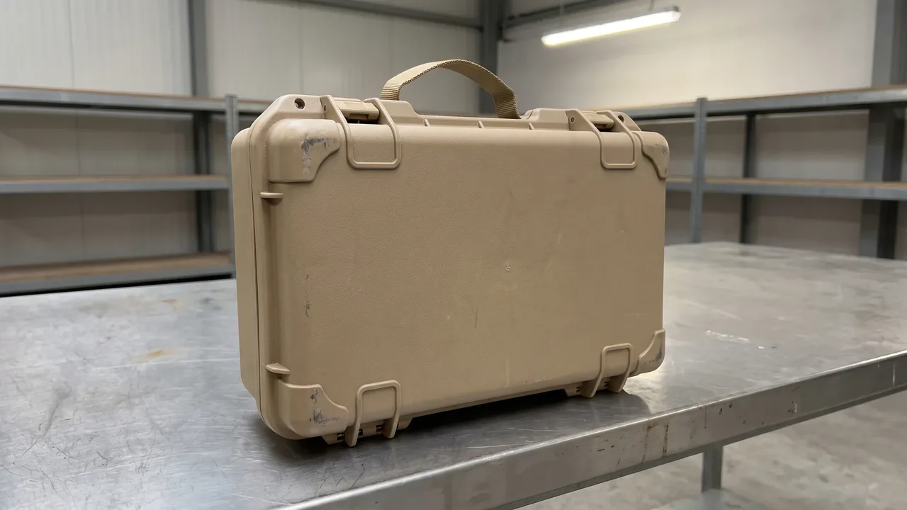
The case shell is the physical foundation of a protective case's load-bearing, sealing and stacking capability. It determines whether the case can stay geometrically stable and structurally intact through drops, squeezing, temperature swings and years of service. For shell buyers, case designers and OEM molders, shell selection is not simply picking a material. It is a systematic trade-off among service environment, load requirements, sealing rating, molding process, tooling cost and production volume. The wrong material leaves a shell brittle at low temperature or degraded by ultraviolet light; poor wall thickness and rib design lets the case collapse under stacking or close with an uneven lid gap; the wrong molding process leaves the seal groove too imprecise for the protection rating to be delivered. This article explains the structural principles and molding points of a protective case shell across function, material system, wall thickness and ribs, injection and blow molding, metal shell forming, mold design, seal grooves, latch and hinge seats, embedded inserts, stacking structure, surface treatment, lightweighting, defects and acceptance, and connects that thinking to What Common Plastic Materials Are Used in Protective Cases? and How Do Protective Cases Achieve Stable Stacking? Stacking Ribs, Locator Bosses, and Interlocking Principles so readers can build a complete shell-engineering framework.
Function of the Shell and Design Inputs
A case shell performs four base functions. First, load bearing: it carries the weight of the contents, the static load of stacking, and the concentrated loads from hoisting and lashing, then transfers them to the ground or the case below, so it needs sufficient stiffness and creep resistance. Second, restraint: working with the liner, latches and gasket, it fixes the contents in place and routes impact loads toward corners and ribs. Third, isolation: it forms the first barrier between the interior and the outside, working with the gasket to achieve water and dust protection and, to some degree, blocking ultraviolet light and temperature swing. Fourth, interface: it provides mounting references for latches, hinges, handles, wheels, pressure valves and stacking corners so accessories integrate reliably.
Design inputs must be fixed before tooling, because later mold changes are extremely costly. Typical inputs include the size, weight and center-of-gravity distribution of the contents; expected drop height and stacking layers; the temperature range, humidity and ultraviolet exposure of the service environment; the required protection rating such as IP67 and the sealing method; expected annual volume and batch count; and the degree of automation in transport and storage. Turning these inputs into a design brief and then deriving material, wall thickness, ribs and process route is standard practice in shell engineering. The goal is not to maximize any single metric but to balance cost, weight and reliability. Over-thickening adds weight and cost while over-thinning sacrifices drop and creep performance, and the weakness usually surfaces in certification testing.
Material System and Selection Logic
Shell materials fall into two broad families: engineering plastics and metals. On the plastic side, ABS (acrylonitrile butadiene styrene) offers high surface hardness, good impact toughness and high molding precision, suiting appearance-critical, high-volume small and medium cases, though its low-temperature brittleness is noticeable. PP (polypropylene) and polypropylene copolymer resist chemicals, stay tough at low temperature and have low density, suiting outdoor, wet and cold conditions. Modified engineering plastics balance rigidity, toughness and weather resistance through blending and impact modification, and are common where overall performance matters. Polycarbonate and its alloys are known for high impact strength, suiting heavy-load cases that must resist strong shock. These trade-offs are covered in What Common Plastic Materials Are Used in Protective Cases?.
On the metal side, magnesium-aluminum alloy offers high rigidity, good thermal conduction and inherent shielding, fitting heavy cases that need crush resistance, heat conduction or electromagnetic compatibility, but it requires anodizing for corrosion resistance. Stainless steel shells resist corrosion very well but are heavy and costly, so they appear mainly in special industrial settings. Composites such as glass-fiber or carbon-fiber reinforcement win on weight and specific strength for carry-sensitive cases. Selection should answer three questions: over what temperature range will the case serve, what drop and stacking loads must it take, and at what process and volume will it be produced. Matching the answers against material properties yields a reliable plan rather than a decision driven by habit or price alone.
Wall Thickness, Ribs and Structural Mechanics
Wall thickness is one of the most sensitive parameters in shell design. Too thin causes short shots in molding, insufficient stiffness and poor drop resistance; too thick adds weight and cost and produces sink marks, warpage and internal stress during molding, which lowers reliability instead of raising it. In engineering practice, wall thickness is set from case size, material flow behaviour and load case, with finite element analysis used to review stress concentration zones. Thickness need not be perfectly uniform: local thickening at load points and local thinning elsewhere, combined with ribs, is the more economical approach.
Ribs are the most effective way to raise stiffness. A well-designed rib layout can multiply the bending inertia of a panel several times with almost no weight gain. Design points include keeping rib thickness at roughly one-half to two-thirds of the main wall, since thicker ribs form sink marks at the root; running ribs along the main load direction with fillets at intersections to reduce stress concentration; matching rib height to spacing so tall thin ribs do not under-fill during molding; and adding ring reinforcement at edges and corners so drop impact is routed into corner posts rather than the middle of a panel. For cases that must carry heavy stacking loads, load pillars or locator bosses should be placed at matching positions on base and lid so upper weight passes directly through column structures instead of pressing on the mid-panel.
Injection Molding Versus Blow Molding
Injection molding is the most common process for protective case shells. Plastic is melted in the machine, injected under high pressure into a closed mold, cooled and ejected. Its advantages are high precision, even wall thickness, and the ability to form ribs, latch seats, seal grooves and insert mounting points in one shot, making it the first choice for complex, dimensionally strict small and medium cases. Its drawbacks are high tooling cost, long development time, and the need for careful gate and cooling design to avoid sink marks and warpage. For high-volume standard cases with complex structure, injection molding is usually the default.
Blow molding suits large hollow cases. A parison is extruded or injection molded, then compressed air is fed into the mold to press it against the cavity. Its advantages are good integrity, no parting seam, strong impact resistance and relatively lower tooling cost, making it suitable for large-volume cases. Its drawbacks are lower wall thickness control and limited ability to form fine ribs and precise seal grooves, so complex internal features are hard to mold in one shot. In practice, a common route is to blow-mold the main body and then achieve the seal groove and latch seats through secondary machining or accessory assembly; another route combines injection-molded lid and base with a blow-molded mid-frame to balance precision and volume. Process choice should follow case size, structural complexity, precision requirement and volume rather than the assumption that one process is simply better.
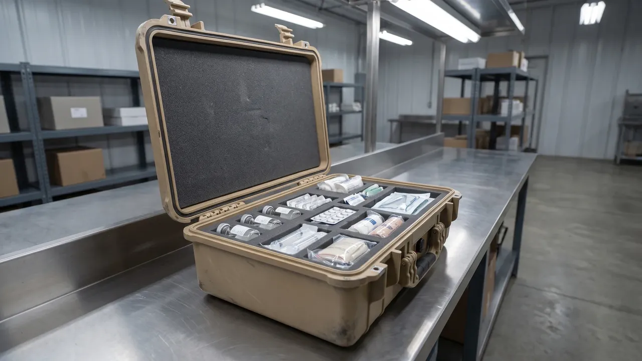
Metal Shell Forming and Composite Structures
Metal shells follow a clearly different route. Common processes combine stamping, bending, drawing and welding: stamping forms flat panels and shallow cavities, drawing forms deeper hollow cavities, bending creates edges and flanges, and welding joins parts into a case body. Metal shells offer high rigidity, strong crush resistance, good dimensional stability and no softening at high temperature, but they are heavy, costly, process-intensive, and prone to stress concentration and corrosion at welded edges. To improve corrosion resistance, magnesium-aluminum shells usually use combined anodizing and coating, while stainless steel shells are passivated or brushed.
In real products, metal-plastic composite structures are increasingly common. A metal frame or profile can serve as the load-bearing skeleton with engineering-plastic panels or corner parts as the outer layer, balancing rigidity and weight. Alternatively, a plastic shell can be the main body with metal inserts at latch and hinge seats so concentrated loads spread into more reliable structure. The key in composite design is the interface. Different thermal expansion coefficients create internal stress under temperature swing, so joints need sensible tolerance allowance or an elastic transition layer, and metal-to-plastic contact points should avoid galvanic corrosion, using insulating shims where necessary. Used well, composite structures significantly raise load capacity and durability without a major weight penalty.
Mold Structure and Forming Tolerance
The mold is the source of shell quality and consistency. Several parameters matter most. The parting line position fixes where the case seam runs and should avoid main load zones and seal grooves while placing flash where it is easy to remove. Draft angle must be sufficient, or demolding scratches the surface or distorts the part, and too little also affects ejection. Shrinkage must be set accurately from material and wall thickness; under-compensation makes parts undersized and latches misaligned, while over-compensation produces uneven lid gaps. Gate position and count affect melt front flow and weld line location; a weld line falling on a seal groove or load zone sharply reduces strength, so mold-flow analysis should predict and adjust it.
Tolerance allocation is equally important. For a case with lid and base, the depth and width of the seal groove and the gasket section must be co-designed so that, once compressed, the gasket has a sensible compression ratio that neither deforms permanently from over-compression nor leaks from under-compression. Mounting hole tolerances at latch and hinge seats should let accessories open and close smoothly without jamming from cumulative tolerance. The positional tolerance of stacking corners and locator bosses decides stack alignment accuracy, and excessive deviation tilts the upper case. In practice, critical mating dimensions are listed as key control items and combined with first-article inspection and batch sampling to ensure consistency. Mold maintenance also matters, because cavity wear changes dimensions over long production runs and should be checked and repaired on schedule.
Seal Groove, Mating Faces and Protection Rating
The seal groove is one of the most precision-critical features in shell design because it directly decides whether the case reaches its rated protection. The groove usually sits on the case flange, running continuously around the opening, and holds the gasket. Design must match groove depth and width to the gasket section: too shallow gives insufficient compression, too deep prevents enough contact pressure, too wide lets the gasket shift, and too narrow makes assembly hard and can shear the gasket. For a lip gasket, the lip loading direction should be designed so the closing lid opens the lip outward for adaptive sealing.
Flatness and roughness of the mating faces matter just as much. If the lid and body faces are not flat, a local gap forms even with an intact gasket, and a spray or immersion test will leak. Design should therefore suppress warpage with ribs near the mating faces and control post-molding deformation. For IP67 and above, local reinforcement near latch compression points is usually added so the compression force is evenly distributed. Sealing and shell are mutually dependent: the gasket is only an elastic element, and what really decides sealing reliability is the uniform compression and stable geometry the shell provides. If the shell deforms from a drop or stacking, the groove deforms with it and sealing falls, in which case repair or replacement should be assessed using the approach in Can a Protective Case Be Repaired? Fixing a Cracked Shell.
Latch Seats, Hinge Seats and Embedded Inserts
Latch and hinge seats are the shell zones that take concentrated loads. A latch transfers force to the case during compression and theft resistance, so its seat needs enough thickness and sensible reinforcement so it is not torn apart or does not dent the wall locally under load. A common design places radial ribs behind the latch seat to spread force over a larger area, and for heavy cases a metal backing plate can be embedded so screw loads do not act directly on plastic. A hinge seat takes the bending moment of repeated lid opening, so it should have a thickened mounting boss and a metal pin so the hole does not wear oversize and misalign the lid. Related accessory selection and fit are covered in Case Latch: Pressure and Theft Resistance Hardware for Protective Cases.
Insert design must respect molding limits. A metal insert is placed in the mold before injection, then fixed as melt surrounds and cools. The insert therefore needs suitable knurling or grooves to resist pull-out and rotation, and its thermal expansion must not differ too much from the surrounding plastic or cracking appears on cooling. Where embedding is impractical, a post-installed nut or a self-tapping screw with a reinforced boss can be used. Handle mounts, wheel mounts and pressure valve seats are also inserts or load points and should be designed together under concentrated-load conditions. Because shell accessory interfaces are hard to change once molded, dimensions and load requirements should be confirmed with accessory suppliers during development, solving problems before tooling starts.
Stacking Structure and Locator Design
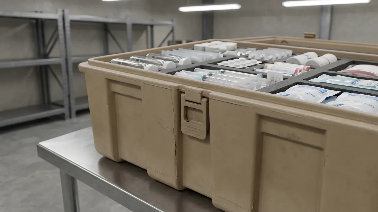
Stacking capability is a key metric of shell design, especially in warehousing and multimodal transport. Case Stacking Corner: Load-Bearing and Alignment Hardware for Stacked Cases and the case's own stacking structure together decide stack stability. At the shell level, a common approach places load pillars or reinforced bosses on the base that match grooves or locator slots on the lid, so stacked cases transfer force directly through column structures instead of pressing on the mid-panel and collapsing it. The lid often carries locator bosses and the base matching recesses to interlock and prevent lateral slip. Where many layers are stacked, the long-term creep of the bottom case should be assessed, raising the material's creep resistance or increasing the bearing area if needed.
Locator design also covers error-proofing and guidance. For cases meant to stack quickly, edge chamfers and guide slopes greatly improve alignment speed. For mixed-size stacks, a transition board or adapter avoids a small case pressing on the lid gap of a large one. The details of stacking structure are covered in How Do Protective Cases Achieve Stable Stacking? Stacking Ribs, Locator Bosses, and Interlocking Principles. A reminder: stacking is a static load case, and dynamic shock in transit still has to be absorbed by the liner, so the two roles are distinct. The shell's stacking goal is to route static load reliably into corners and pillars without a significant weight penalty, so that after long storage the case has not collapsed, tilted or deformed permanently.
Surface Treatment, Texture and Weather Resistance
Shell surface treatment affects both appearance and durability. Engineering-plastic cases usually get a leather or matte texture from mold etching, which hides flow marks and minor sink marks while improving grip friction and wear performance. Texture depth must be balanced: too deep creates stress concentration on impact, too shallow fails to hide defects. For outdoor cases, UV stabilizers or color masterbatch can be added to slow fading and chalking under long sunlight. Note that a dark shell heats up noticeably in strong sun, so if contents are temperature-sensitive, a lighter shell or an insulating liner reduces the heat load, consistent with the environmental control approach in Optical Instrument Case: Zoned Protection and Shock Isolation for Precision Optics.
Metal shells mainly use anodizing, coating and passivation. Anodizing forms a dense oxide film on aluminum that improves corrosion and wear resistance; coating adds color and extra protection but needs attention to adhesion and impact resistance; passivation suits stainless steel by restoring and strengthening its natural passive layer. Whether plastic or metal, surface treatment should avoid additives that migrate or exude, which could contaminate contents or react with the gasket. For marking, long-service shells should use molded raised lettering or laser etching rather than stickers that peel and blur outdoors. Surface treatment may look minor, but it directly affects weather resistance and service life in real environments.
Lightweighting, Thinning and Material Recovery
Lightweighting is a continuing goal in shell design, especially for carry and air-transport applications where case weight affects both user experience and freight cost. Methods include choosing lower-density or higher-specific-strength materials; using topology optimization and rib design to put material only where it carries load; thinning non-load zones without cutting thickness at critical points; and using composite structures with a metal skeleton and plastic panels instead of an all-metal shell. The precondition is not to sacrifice drop or stacking performance, so lightweighting must rest on test data rather than weight cutting alone.
Material recovery and sustainability are also drawing buyer attention. Thermoplastics such as PP and ABS are theoretically recyclable, but in practice the ratio and source of regrind affect performance consistency, so it is usually used cautiously in non-load or non-appearance parts with clear marking and verification. For shells in long outdoor service, extending service life is itself the most effective way to cut carbon, so reliable structure and repairability matter more than using recycled material alone. Design should also consider disassembly: making metal inserts separable from the plastic body helps sorting at end of life. Weighing lightweighting, durability and recyclability together is the mark of a maturing shell-engineering practice.
Defects, Inspection and Quality Consistency
Common shell defects include sink marks, warpage, weak weld lines, flash, gas marks and short shots. Sink marks appear mainly at thick walls and rib roots and can be improved by thinning ribs, optimizing gates and extending hold pressure. Warpage comes from uneven cooling and shrinkage difference and can be controlled by balancing cooling circuits and mold temperature. Weld line strength depends on melt front temperature and pressure and can be improved by relocating gates so the weld line avoids load zones. Flash relates to clamping force, mold wear and injection pressure. Identifying causes and establishing a process window is the basis of batch consistency.
Inspection should cover dimensions, appearance and performance. Dimensional checks focus on case opening flatness, seal groove dimensions, mating clearance and mounting holes. Appearance checks cover surface defects, color difference and texture consistency. Performance checks include drop, stacking, spray or immersion, vibration and temperature cycling, verified against the rated protection where needed. For volume production, first-article inspection and in-process sampling should be established, with mold maintenance and process change records retained so a batch problem can be traced quickly. Shell consistency directly decides whether the protection rating is reproducible: if dimensional variation within a batch is too large, even a sample that passes testing cannot guarantee that the whole batch will stay reliable in service.
Standards, Acceptance and Export Compliance
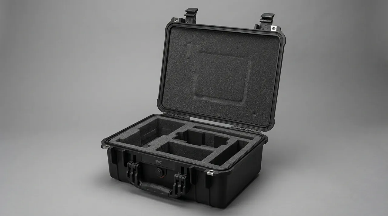
Protective case shell quality is usually judged against general protective-case standards and related specifications. Typical yardsticks are IP ratings and MIL-STD-810H environmental engineering and test methods, plus the domestic industry and military specifications that address drop, vibration, rain, dust, salt fog and low pressure. Because the shell is the load-bearing and sealing body, drop and stacking results matter most, since they best reflect whether the structural design is sound. At acceptance, buyers should require material reports such as material certificates and flame class, dimensional inspection reports and performance test reports, and should specify tolerances for critical mating dimensions. If the shell is supplied together with liner, latches and gasket, interface dimensions must be confirmed; liner schemes are covered in Case Foam Lining: Cushioning and Customization of Case Interiors.
A purchase specification should include at least material grade and additive requirements, wall thickness and rib scheme, molding process, critical mating dimensions and tolerances, surface treatment, load and drop conditions, certification basis and acceptance items. For larger projects, mold-flow analysis before tooling and a full first-article dimensional and performance validation after trial molding are recommended before volume production. Finally, a clear note: this article discusses only the material and molding process of the protective case shell as a container structural component and does not address the properties of any protected items. Cross-border transport and export of related products must follow local laws, regulations and export-control requirements and be assessed separately by the responsible party; nothing here constitutes a compliance conclusion.
FAQ
Q: Should a protective case shell use ABS or PP, and how do you decide? A: Decide from service environment, appearance requirement and process volume rather than price alone. ABS offers high surface hardness, good impact toughness and high molding precision, suiting appearance-critical, high-volume small and medium cases, but its low-temperature brittleness is noticeable and long outdoor UV exposure requires a UV stabilizer. PP and polypropylene copolymer resist chemicals, stay tough at low temperature and have low density, suiting outdoor, wet and cold conditions, though surface hardness and finish are slightly lower. If the case is used mainly indoors at normal temperature and appearance matters, ABS is often the better fit. If it must serve in cold, humid or chemically exposed settings, copolymer polypropylene is safer. For cases needing overall performance, modified engineering plastics or PC alloys balance rigidity, toughness and weather resistance. Final confirmation should rest on drop and stacking test data rather than intuition or a single datasheet value. Recording the chosen grade on the drawing also prevents a silent substitution in a later production run, and a simple cold-chamber drop test settles the argument quickly.
Q: Is a thicker wall always better, and how should ribs be designed? A: Thicker is not always better; wall thickness and ribs must be designed together. Too thin a wall causes short shots in molding, insufficient stiffness and poor drop resistance. Too thick a wall adds weight and cost and produces sink marks, warpage and internal stress during molding, lowering reliability instead. A sounder approach is to thicken load points moderately, thin non-load zones moderately, and use ribs to raise overall stiffness. Rib thickness is usually kept at one-half to two-thirds of the main wall, since thicker ribs form sink marks at the root. Ribs should run along the main load direction with fillets at intersections to reduce stress concentration. Edges and corners should have ring reinforcement so drop impact routes into corner posts. For cases carrying heavy stack loads, load pillars should be placed at matching positions on base and lid so weight passes through columns. Keeping the pillar height consistent across the batch is what actually makes mixed-case stacking predictable on a busy loading dock, and it costs nothing at the tooling stage.
Q: How do you choose between injection molding and blow molding? A: Judge from case size, structural complexity, precision requirement and volume. Injection molding gives high precision and even wall thickness and can form ribs, latch seats, seal grooves and insert mounting points in one shot, suiting complex, dimensionally strict small and medium cases, but tooling is costly and development long. Blow molding gives good integrity, no parting seam, strong impact resistance and relatively lower tooling cost, suiting large hollow cases, but wall thickness control is lower and fine ribs and precise seal grooves are hard to form. In practice, a common route blow-molds the main body and achieves the seal groove and latch seats through secondary machining, while another combines injection-molded lid and base with a blow-molded mid-frame. Where sealing rating and fit precision matter, injection is usually more reliable; where large volume at low cost matters, blow molding wins. Sampling both processes with the same part geometry is the fastest way to feel the difference in precision and cost before committing to tooling.
Q: Why is seal groove design so critical, and what are the key points? A: The seal groove directly decides whether the case reaches its rated protection, so it carries the highest precision requirement. Key points include matching groove depth and width to the gasket section: too shallow gives insufficient compression, too deep prevents enough contact pressure, too wide lets the gasket shift, and too narrow makes assembly hard or shears the gasket. For a lip gasket, the lip loading direction should be designed so the closing lid opens the lip outward for adaptive sealing. Flatness and roughness of mating faces must be controlled, because an uneven face forms a local gap and leaks; ribs near the mating faces suppress warpage. For IP67 and above, local reinforcement near latch compression points evens out the compression force. The shell provides the stable compression geometry and the gasket provides the elasticity, and neither alone can deliver sealing. A quick squeeze test with the gasket installed and the lid latched reveals uneven compression long before a formal spray test does, so it belongs in the trial process.
Q: What scenarios suit a metal shell versus a plastic shell? A: Each has clear boundaries. A metal shell is rigid, resists crushing, holds dimensions well and does not soften at high temperature, and magnesium-aluminum also shields inherently, suiting heavy cases that need crush resistance, heat conduction or electromagnetic compatibility. It is heavy, costly and process-intensive, however, and welded edges are prone to stress concentration and corrosion, so anodizing or coating is essential. A plastic shell is light, precise, low-cost and chemically resistant, suiting most portable and medium-load uses, but it loses stiffness at high temperature and long-term loading requires attention to creep. Composite structures are common in practice, such as a metal skeleton with plastic panels, or metal inserts at latch and hinge seats in a plastic body, balancing rigidity and weight by spreading concentrated loads into reliable structure. That is why the shell supplier and the accessory supplier should agree on the interface drawing at the same design review rather than in sequence, so neither side discovers a mismatch after the molds are already cut.
Q: Does thinning the shell for lightweighting sacrifice protection? A: Lightweighting must rest on test data, never on weight cutting alone, or protection will be sacrificed. Workable methods include using lower-density or higher-specific-strength materials, using topology optimization to place material where it carries load, thinning non-load zones without cutting thickness at critical points, and adopting composite structures with a metal skeleton and plastic panels. The risk of thinning is lower drop and creep resistance, especially in cold conditions where material toughness already drops and thin walls crack more easily, so any thinning plan must be validated by drop and stacking tests. Thinning also lengthens the melt flow path, which can cause short shots and weak weld lines, so gate and process windows must be adjusted in step. Only after validation is lightweighting reliable and worthwhile. A simple before-and-after weighing of a stripped shell, combined with the same drop test on both versions, shows whether material was removed where it mattered least.
Q: How should sink marks and warpage in a shell be improved? A: Sink marks and warpage are the most common molding defects and should be improved through material, structure and process together. Sink marks appear mainly at thick walls and rib roots and can be reduced by thinning ribs, optimizing gate position and size, extending hold pressure and adjusting mold temperature. Warpage comes from uneven cooling and shrinkage difference and can be controlled by balancing cooling circuits, adjusting mold temperature, smoothing wall thickness transitions and adding fixture cooling. Structurally, avoid abrupt thickness changes and use gradual transitions and fillets to reduce internal stress. On the material side, a grade with more stable shrinkage or glass-fibre reinforcement can help, but note the anisotropy from fibre orientation. Process parameters should be recorded as a stable window so batch variation from material or mold changes is avoided. Defects on critical mating features should be fixed by mold repair rather than post-correction. Keeping a defect photo library from each mold trial helps the shop floor recognise the same signature when it reappears months later on a new batch.
Q: What documents should a buyer request from a protective case shell supplier? A: Three categories matter most. First, material and process documentation, including material grade and additive requirements, flame and weather class, wall thickness and rib scheme, molding route, surface treatment and color code, to judge whether they meet the service environment and appearance. Second, dimensional and mold documentation, including critical mating dimensions and tolerances, case opening flatness, seal groove dimensions, mounting holes, mold-flow conclusions and full first-article dimensional reports, to assess batch consistency. Third, performance and compliance documentation such as IP rating, MIL-STD-810H or corresponding industry and military drop, vibration, rain, dust, salt-fog and stacking test reports, along with material certificates and related certification files. After delivery, establish first-article inspection and in-process sampling to check dimensions, appearance and performance, and file mold maintenance and process change records to keep long-term supply stable and reliable. Storing these documents with the drawing revision makes any later dispute about material or process straightforward to resolve, and it shortens the next order.