

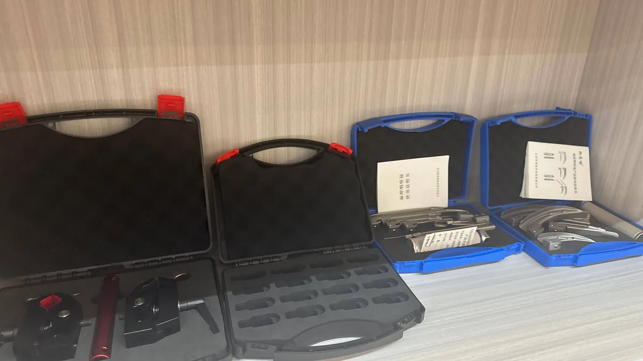
A single 5,000 tonne per day clinker line consumes wear parts by the thousand tonnes every year. Grinding rolls, table liners, clinker cooler plates, blow bars, bucket elevator scoops and bucket teeth share three traits: high unit mass, edge-critical geometry, and precision mating faces. They also live in the dustiest, hottest sections of the plant. The protection principle is simple: wear parts are not defeated by abrasion during transport but by chipped edges, scratched mating faces and distorted bolt holes, while inspection instruments are not defeated by vibration but by dust ingress and condensation. JUNZHIJIA addresses this by separating the two cargo families physically and solving each with its own case structure, liner logic and sealing grade.
A major shutdown window is often only seven to fifteen days, and parts arrive from several suppliers in several batches within it. The case therefore has to deliver a kit that can be installed straight from the box, with part numbers, fasteners and assembly sequence all correct. This article sets out the component families and failure environments, dust-ingress countermeasures, thermal exposure management, heavy-load support, moisture control and transport verification that the job requires.
Table of Contents
- Component Families and Failure Environments Across Five Plant Stages
- Logistics Characteristics of Wear Parts: Weight, Edges and Mating Faces
- How Dust Enters and How to Choose a Protection Level
- Four Dust-Ingress Countermeasures and Their Limits
- Managing Thermal Exposure Near the Kiln and Cooler
- Seal Faces and Gaskets Under Heavy Dust
- Clean Containment for Inspection Instruments
- Liners and Compartments: Support and Location for Heavy Parts
- Moisture and Corrosion Control in Monsoon and Open Storage
- Heavy-Load Lifting and Forklift Interfaces
- Transport Testing and Incoming Acceptance
- Batch Consistency and the Custom Delivery Process
- Frequently Asked Questions FAQ
- Conclusion and Related Reading
Component Families and Failure Environments Across Five Plant Stages
Conditions vary so widely along a cement line that a case designed for a generic plant will be over-built in some areas and inadequate in others.
Raw meal preparation centres on vertical roller mills and roller presses. Grinding roll tyres and table liners are high-chromium castings or hardfaced composites weighing two to six tonnes each. Their edges carry the termination of the hardfacing, and an impact chip there cannot be repaired on site; the whole component is scrapped. Roller press studs or profile rings are just as expensive, and a crushed profile lowers throughput for months.
The kiln section contributes kiln inlet and outlet plates, back-end seals and refractory anchors. These operate near radiant surfaces between 200 and 1,400 degrees Celsius. They have cooled by the time they are packed, but if stored within ten metres of the kiln shell or cooler, case interior temperatures can sit fifteen to twenty-five degrees above ambient for weeks.
The clinker cooler section supplies grate plates, grate bars and hammer heads. Grate plates are heat-resistant castings with thin walls and many apertures, so the webs between holes are the smallest cross-sections in the whole plant. They are the components most vulnerable to point loading and stacked compression.
The cement mill section combines large flat liners and partition diaphragms with grinding media, producing the classic mixed logistics problem of edge-sensitive plates plus a very dense free-flowing bulk material.
The packing and dispatch section handles bucket elevator scoops, screw conveyor flights and packer metering components. Geometry is fairly regular, but dust concentration is the highest in the plant, and long storage fills every case seam with cement powder.
| Stage | Typical components | Cargo characteristics | Dominant failure mode |
|---|---|---|---|
| --- | --- | --- | --- |
| Raw meal preparation | Roll tyres, table liners, press rolls | 2 to 6 tonnes, hardfaced edges | Edge chipping, roll face marking |
| Kiln | Inlet plates, anchors, seal strips | Heat-resistant, irregular | Thermal distortion, hole misalignment |
| Clinker cooler | Grate plates, grate bars, hammers | Thin-walled, apertured, brittle | Web fracture, stacked cracking |
| Cement mill | Liners, diaphragms, grinding media | Flat plates plus dense bulk | Face indentation, bulk instability |
| Packing and dispatch | Scoops, screw flights, metering parts | Regular but dust-attracting | Seam dust build-up, contaminated faces |
Read as a whole, the table defines the design split. Heavy parts follow a face-support plus edge-relief plus centre-of-gravity marking route. Thin apertured parts follow a full-support plus layer-limited stacking route. Bulk media follow a rigid container plus full-fill route. Instruments follow a clean cavity plus stable-humidity route. The general logic for heavy spare-part logistics is set out in Mining Equipment Parts Cases: Crusher and Conveyor Component Protection, and the specific handling of mill liners and grinding media appears in Ball Mill Liner Cases: Liner Plate and Grinding Media Protection.
Logistics Characteristics of Wear Parts: Weight, Edges and Mating Faces
Wear parts are difficult to pack because three value surfaces coexist on the same component, and each one imposes requirements that conflict with the others.
The working surface is the point of the design. The roll face of a grinding tyre, the grinding grooves of a table liner, the striking face of a blow bar: any indentation changes bed thickness and grinding efficiency. Working surfaces must face inwards and touch nothing hard, which is normally achieved by placing two components face to face with a fifteen to twenty-five millimetre rubber interlayer.
The mating face is the assembly datum. Liner backs, roll tyre bores and flange registers are machined to flatness or roundness tolerances in the 0.05 to 0.20 millimetre band. Support points must avoid these surfaces, or at least interpose a compressible medium-density EVA layer so that metal never bears directly on a finished face.
Edges and holes are the stress raisers. Once a bolt hole goes oval, the site has to ream it out, which weakens the connection. Once a hardfaced edge chips, repair is usually impossible.
The three requirements do not point in the same direction. Working surfaces need cleanliness and freedom from pressure; mating faces need corrosion protection and freedom from scratching; edges and holes need impact resistance. The engineering answer is zoning rather than uniformly thicker foam. Placing a heavy part on a rigid support with a soft interface is more reliable than bedding it in a solid block of high-density foam, because a solid block under a several-hundred-kilogramme point load takes permanent compression set, and the location feature has failed by the second packing.
Unit mass also decides the handling method and therefore the structural class of the case. As a working guide, parts under 25 kilogrammes can be designed around manual handling; 25 to 80 kilogrammes need lifting eyes or mechanical positioning; 80 to 600 kilogrammes require defined lifting points and fork pockets; above 600 kilogrammes the case becomes an engineered structure whose lifting points, base frame and stacking capacity all have to be calculated.
How Dust Enters and How to Choose a Protection Level
Cement dust is difficult to exclude because its particle size distribution is broad, its concentration is high, and it often carries alkaline compounds.
Particle size is the governing variable. Raw meal has a median particle size around ten to thirty micrometres, finished cement around ten to twenty, and filter outlet fines can fall to one to five micrometres. That range approaches or falls below the microscopic clearance of most seal lips, so relying on a single rubber cord to stop it can only delay ingress, not prevent it. Dust near the kiln hood and clinker cooler also carries alkaline oxides, which form a liquid film above pH 12 when damp and attack aluminium and zinc-plated hardware aggressively.
The protection level has to match the duty. Under IEC 60529 and GB/T 4208, first characteristic digit 5 means dust protected: dust must not enter in sufficient quantity to interfere with operation, but complete exclusion is not required. Digit 6 means dust tight: no dust enters under the specified test conditions. Both are verified on a bare enclosure with second digit 0, so the verdict depends entirely on the dust chamber test, in which the case is placed in a chamber charged with talcum powder, a defined negative pressure is maintained inside, and the interior is inspected for visible dust deposits after the specified duration.
Three misjudgements recur. First, treating IP5X and IP6X as interchangeable; in a high-concentration fine-dust environment such as a kiln hood, the small ingress permitted at IP5X is often enough to contaminate instruments within months. Second, assuming that tighter is always better, when a fully sealed case under a large diurnal temperature swing develops a pressure differential that loads the gasket and drives a pumping effect. Third, testing only the shell rather than the assembly, when many leaks originate at seal groove cleanliness, cable entries and valve mounting faces rather than in the moulding itself.
A reliable decision sequence is to fix the target level from the duty, confirm the case was tested fully assembled with valve, latches and cable entries fitted, and then verify by dust chamber test or an equivalent method rather than by visual impression.
Four Dust-Ingress Countermeasures and Their Limits
Dust exclusion is not one measure but a combination of four mechanisms. Understanding the boundary of each prevents the common outcome of fitting something that does nothing.
| Countermeasure | Mechanism | Suitable duty | Principal limitation | Maintenance requirement |
|---|---|---|---|---|
| --- | --- | --- | --- | --- |
| Compressed gasket seal | Elastomer compressed 20 to 30 percent in a groove closes microscopic gaps | Most openable cases with a shared lid structure | Takes compression set under long-term load; fails once the sealing face is contaminated with grit | Periodic paper test, groove cleaning, store unlatched |
| Labyrinth geometry | Tortuous path forces dust to settle and lose kinetic energy | High-concentration coarse dust, frequently opened interfaces | Limited effect on one to five micrometre fines; cannot achieve IP6X alone | Periodic purging of accumulated dust |
| Positive pressure | Ten to fifty pascals of internal overpressure drives dust outward with the airflow | Fixed control cabinets and online instrument enclosures | Requires a continuous air supply; wet or oily air makes contamination worse | Verify air dew point and filter change interval |
| Filtered venting | Hydrophobic membrane passes gas while retaining particles | Sealed cases that must still equalise pressure | Slow equalisation if membrane area is undersized; membrane fails once contaminated | Inspect membrane integrity and flow rate on schedule |
The selection rule compresses to one sentence: frequently opened interfaces rely on gaskets and labyrinths, permanently closed volumes on positive pressure and filtered venting. Transport cases rely mainly on a gasket plus a labyrinth groove, because no air supply exists on the road.
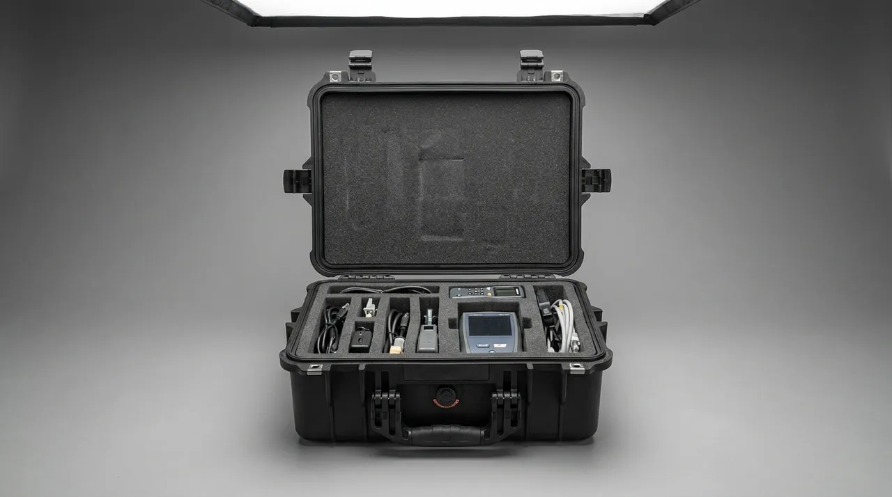
How a venting element equalises pressure without compromising the protection level is covered in Pressure Equalisation Valves on Protective Cases: What They Do and When You Need One.
Managing Thermal Exposure Near the Kiln and Cooler
Thermal exposure in a cement plant differs from that in a steelworks. It is not sustained high temperature but a combination of close-range radiation, slow bulk temperature rise, and rapid cooling.
Storage position matters more than most buyers expect. A spare-part case stored within ten metres of the kiln shell or cooler can run fifteen to twenty-five degrees above ambient at the surface, with the interior following. For elastomers, sustained operation above sixty degrees Celsius accelerates compression set. For desiccant, every ten degree rise shifts the adsorption equilibrium materially and cuts effective capacity.
Material temperature limits must be taken at the worst case. Typical continuous service ranges are roughly minus thirty to plus one hundred degrees Celsius for nitrile rubber, minus forty to plus one hundred and twenty for EPDM, minus sixty to plus two hundred for silicone, and minus twenty to plus two hundred for fluoroelastomer. These are material limits, not sealing limits: compression set accelerates sharply near the upper end, so sound practice is to select on roughly seventy percent of the maximum service temperature and keep the remainder as margin.
Liner materials are equally temperature sensitive. EVA foam begins to soften above sixty degrees Celsius and loses recovery; under sustained compression the rebound loss can exceed thirty percent. Polyethylene foam tolerates temperature slightly better but creeps more readily. Cross-linked IXPE foam holds dimensional stability better at equivalent density. Where a case really must sit near a heat source, specify IXPE or an EPDM-based liner and reduce the stacking tier count.
Condensation during the cooling phase is the most hidden risk. Absorbing heat by day and releasing it at night drives the interior surface below the dew point. Two measures help: fitting a pressure equalisation valve so internal and external pressure track temperature together and less moist air is exchanged, and sizing desiccant by storage duration rather than by one-way transit time.
Test methods for thermal cycling are described in High and Low Temperature Testing for Protective Cases: Verifying a -40 C to +70 C Range, and comparable experience with thermal-section spares appears in Industrial Furnace Cases: Burner and Refractory Component Protection.
Seal Faces and Gaskets Under Heavy Dust
Seal failure is rarely a snapped gasket. The overwhelming majority of failures are a contaminated gasket or a gasket that no longer springs back.
Compression set is the first cause. Measured to GB/T 7759, compression set is the residual deformation after a specimen is held at a defined compression ratio and temperature for a defined time, released, and allowed to recover. The usual engineering requirement for a case is no more than twenty-five percent set after twenty-four hours at seventy degrees Celsius and twenty-five percent compression. Above that figure the gasket still has a visible profile but can no longer generate the required contact stress. The quickest field check is the paper test: close the lid on strips of paper at several points around the perimeter and pull. Resistance should be even; wherever the paper slides out freely, the seal is weak there.
Groove contamination is the second cause. A single 0.3 millimetre cement grain lodged in the seal groove is enough to hold a continuous channel open between gasket and groove wall. Dust exclusion therefore depends on groove geometry as much as on the cord: radius the groove mouth to avoid a dust trap, match groove depth to cord section so the compressed cord does not stand above the groove edge, and brush or low-pressure air-clean the groove before closing.
Stiffness matching is the third factor. A large lid deflects under load, and if lid stiffness is insufficient the gasket compression at mid-span will be noticeably lower than at the corners. Good practice is to limit maximum lid deflection in the installed condition to thirty percent of the seal compression, adding ribs or more latches if it exceeds that. Latch count and spacing should hold the variation in gasket compression between adjacent latches below fifteen percent.
A practical maintenance rhythm is: visual groove inspection after every field opening; a paper test quarterly; gasket replacement every twelve months or on any sign of water ingress. Material comparison is covered in Case Gasket Ageing: How to Tell When a Seal Needs Replacing.
Clean Containment for Inspection Instruments
The inspection instrument inventory in a cement plant is longer than many people assume. Laser trackers and total stations measure kiln shell and tyre concentricity. Ultrasonic thickness gauges assess shell and pipe wall loss. Laser alignment systems true up drive trains. Infrared cameras survey coating and refractory condition. Vibration analysers and gas detectors complete the list.
The common enemy of all of them is dust and condensation, not vibration. A laser tracker interferometer is extremely sensitive to optical surface cleanliness; a single film of fine powder means recalibration. An ultrasonic probe coupling face contaminated with cement paste produces a systematic reading bias. An infrared lens coating damaged by long-term alkaline dust adhesion loses transmission permanently.
Three design principles follow. First, clean cavity: line with closed-cell or skinned material so that open-cell foam does not absorb dust and become a secondary contamination source. Second, independent compartments: store the instrument body, probes, cables and calibration artefacts separately so a probe cannot strike the body in transit. Third, controlled humidity: size desiccant to the internal net volume and include a visible humidity indicator card so condition can be judged immediately on arrival.
Desiccant quantity is calculated from net volume. For silica gel in a moderate-humidity duty, a working figure is 200 to 400 grammes per cubic metre of internal volume, rising to 500 to 800 grammes for long sea voyages. Effective capacity falls sharply as temperature rises, so where storage is warm the charge should be increased by at least thirty percent.
Calibration artefacts are the most neglected items. Tracker spherically mounted reflectors and standard bars are measuring instruments; an impact ends their accuracy. They should be located in machined medium-density EVA nests with finger reliefs that let an operator lift them out without using a tool as a lever.
Liners and Compartments: Support and Location for Heavy Parts
A liner is not padding. It is a structure that transfers load from the cargo into the case.
The first layer is the compression layer. It sits in the base and spreads concentrated load across the case floor. For metal parts above one hundred kilogrammes, use 60 to 80 kilogrammes per cubic metre EVA or a rubber pad twenty to thirty millimetres thick. Above five hundred kilogrammes, foam alone will take permanent set; use a rigid cradle with a thin elastomeric interface, so the foam only accommodates surface irregularity and never carries the load.
The second layer is the location layer. It decides whether the cargo can move horizontally. Liners are located by side stops, and the stop height should be thirty to fifty percent of cargo thickness. Irregular parts such as roll tyres and kiln-end liners should sit in machined conformal cradles in which the contact area is at least sixty percent of the projected area, so stress is not concentrated. Location clearance should be held to 0.5 to 1.5 millimetres: too tight and the part will not drop in, too loose and it will shift.
The third layer is the energy-absorbing layer, placed at edges and corners. Low-density polyethylene foam at 25 to 35 kilogrammes per cubic metre and twenty to forty millimetres thick removes peak load effectively. It does not replace the location layer. Locate first, absorb second; reverse the order and the cargo moves before it meets the absorber, and the foam is punctured.
Compartment layout should mirror the assembly sequence. Group by mill model or plant stage so that the complete liner, bolt, washer and seal set for one shell section sits in the same compartment or an adjacent one, and the site can lay out an installation straight from the box. This sequence-driven approach matches the component-type zoning described in Warehouse Rack and Steel Structure Cases: Upright and Beam Component Protection.
One practical check. After liner assembly, carry out a trial closure and hold the gap between lid and body to zero to two millimetres. Confirm the latch closing force does not exceed design, because an over-thick liner leads operators to latch only partially.
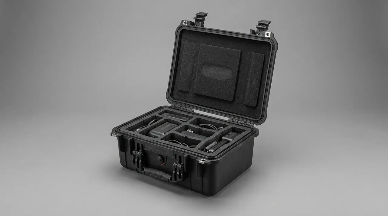
Moisture and Corrosion Control in Monsoon and Open Storage
Cement plants mostly store spares outdoors or in open-sided sheds. Relative humidity in the monsoon season stays above eighty-five percent for months, and in some regions sea air adds chloride.
The driving force for corrosion is condensation, not rainfall. As long as an interior surface falls below the dew point, water vapour condenses directly onto metal. That explains how a case can look intact while the contents are already rusting: moisture migrates in during temperature cycling. The first priority is therefore to reduce the total water vapour inside the case, and only then to block external water.
A three-layer approach works well. The inner layer is a vapour-phase corrosion inhibitor film or paper, kept within 300 millimetres of metal surfaces to maintain an effective concentration. The middle layer is a barrier bag in polyethylene or aluminium composite, heat sealed. The outer layer is the case itself. Machined faces such as registers, bores and flanges should receive a thin rust-preventive grease before wrapping; cast surfaces should not, because thick grease traps dust and forms an abrasive paste.
Size desiccant by total storage time, not transit time. Where cargo may sit in a transhipment port or remain in store for months after arrival, size for three months or more, and fit a humidity indicator card with 10, 20, 30 and 40 percent trigger points so condition can be judged without opening the case. Case hardware needs protecting too: steel reinforcement, latches, hinges and rivets will rust in chloride air unless specified properly. Common practice is 304 or 316 stainless, or zinc-plated carbon steel with a sealing topcoat, compared by ASTM B117 exposure as described in Salt Spray Testing for Protective Cases: Reading Corrosion Results Correctly rather than treated as a service-life prediction. Finally, keep cases at least one hundred millimetres off the ground, clear standing water from the lid after rain, and open long-stored units every three months to check for rust spots, liner moisture uptake and shell distortion.
Heavy-Load Lifting and Forklift Interfaces
Single cases in a cement plant frequently exceed one tonne, so lifting and fork interfaces decide handling safety.
Lifting points must land on primary structure. The commonest error is to bolt an eye to a panel, when panels are typically only twelve to eighteen millimetres thick and will tear out at the moment of lift. The correct arrangement passes the eye base through the panel and anchors it to an internal steel beam or base frame, with positions confirmed by calculation rather than estimation. Design the lifting system to a factor of four.
Fork pockets must match site equipment. State the clear height, clear width and centre distance, and give the permitted tine spacing range and minimum insertion depth. Tines set too close concentrate load at the middle of the base; set too wide they bear on unreinforced edges; inserted too shallow they leave the centre of gravity outside the supported region. Fit location blocks under the base to engage pallet or vehicle floor stops and prevent the unit sliding.
Mark the centre of gravity honestly. A table liner case may be offset 150 to 400 millimetres depending on the component mix, so mark the actual projection rather than drawing it at the geometric centre. Where offset is significant, add sling routing guidance and a no single-point lift warning.
Stacking must be checked against design load. With two tiers on a pallet, the bottom case carries the upper case weight multiplied by a dynamic factor of 1.5 to 1.8 for road transport, so the design load often reaches 2.5 to 3.6 times a single case weight. Load must travel from the upper case corner posts into the lower case posts, never into the liner surface. For units above 600 kilogrammes, limit stacking to two tiers and print the maximum tier count and a no-side-stacking symbol on the case.
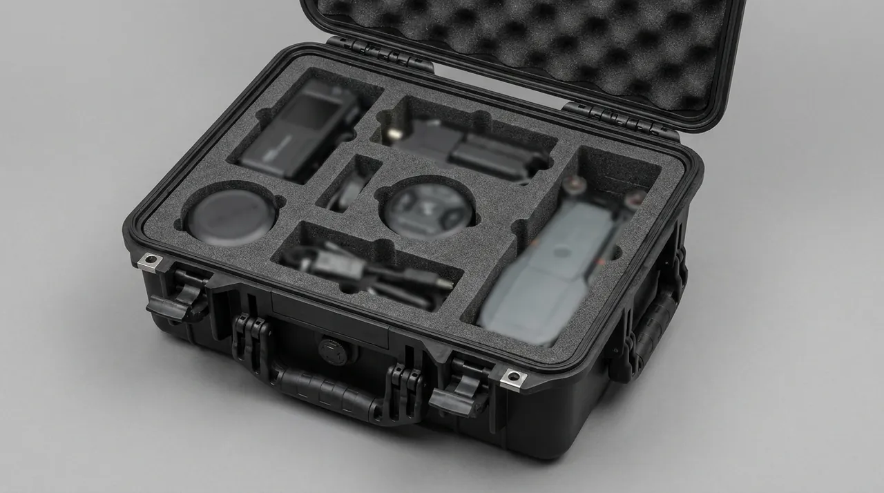
Transport Testing and Incoming Acceptance
The purpose of transport verification is not to obtain a certificate but to confirm that the case still protects the cargo on the worst realistic route.
| Test | Common standard | Application notes |
|---|---|---|
| --- | --- | --- |
| Vibration | GB/T 4857.7, ASTM D999 | Simulates sustained road and rail vibration |
| Drop and impact | GB/T 4857.5, ISTA series | Drop height set by mass; verifies edges and corners |
| Stacking | GB/T 4857.3, GB/T 4857.4 | Verifies creep and stability under long storage |
| Incline impact | ASTM D880 | Simulates marshalling and emergency braking |
| Distribution cycle | ASTM D4169 | Allocates test severity across the actual route |
| Salt spray | ASTM B117, GB/T 10125 | Comparative assessment of hardware corrosion |
These standards are not mutually exclusive. A common arrangement uses GB/T 4857 for the basic items and ISTA or ASTM D4169 for whole-pallet verification. ISTA selects its procedure by mass and transport mode and suits parcel and e-commerce flows, as described in How Is ISTA Transport Testing Performed? Standard Drop and Vibration Procedures. MIL-STD-810H is an environmental test method standard, cited when environmental robustness must be assessed; it is not a product certification.
Incoming acceptance should follow a seven-point written checklist: shell free from cracking, collapse and distortion, with seals intact; tilt indicator not triggered; humidity card within limit and desiccant unsaturated; wear-part faces unmarked, edges unchipped and bolt holes not ovalised; fastener kits matching the packing list; lifting points and fork pockets undistorted; and documentation complete. Photograph any anomaly with a scale reference and the case serial number visible.
Batch Consistency and the Custom Delivery Process
Cement groups typically order once, receive in several batches, and distribute to several plants, so batch consistency matters more than single-unit performance. If the first liner batch fits and the second does not, the site is left with no workable option.
Three controls hold consistency. Liner machining uses one digital model and one datum across all batches. Critical case dimensions, including cavity length, width and height, corner post position, lifting point coordinates and fork pocket spacing, are included in batch sampling. Every batch retains first-article photographs and a record of key dimensions.
A six-stage custom process is recommended. First, supply component drawings, unit mass, centre of gravity, quantity per case and equipment model. Second, receive the structure proposal, liner zoning drawing and mass estimate. Third, verify a prototype loaded with real components under static stacking and a short road run. Fourth, run the agreed vibration, drop or stacking tests. Fifth, produce a pilot batch to confirm assembly rhythm. Sixth, deliver in volume and retain batch records. The economics of tooling and minimum batch size are analysed in Does a Custom Protective Case Require a New Mold? Injection Mold Costs and Batch Thresholds Explained.
The three most common mistakes are underestimating case gross mass, setting unrealistic liner tolerances, and ignoring the site's actual lifting capability. A single prototype verification prevents all three, and it costs far less than a shutdown caused by parts that will not fit or that arrive damaged.
Frequently Asked Questions FAQ
Q: Can wear parts and inspection instruments share the same case?
A: Do not mix them in one cavity. The two cargo families impose opposite requirements. Wear parts need rigid support, generous location clearance and impact tolerance. Instruments need a clean, low-vibration, humidity-controlled cavity where even a thin dust deposit can degrade optical or metrological performance. When they travel together, the usual result is that a heavy casting shifts, drags abrasive dust into the instrument compartment, or transmits shock into equipment never designed to absorb it. A workable compromise is one case with two sealed compartments separated by a solid full-height divider. Each cavity then gets its own base load path, its own liner strategy and its own desiccant charge. The instrument cavity is sealed and lined with closed-cell material; the heavy cavity is built around structural cradles and positive location. Even then, separate shipments are usually the better answer. The space lost costs far less than a damaged tracker, and better pallet layout recovers most of it.
Q: Should a cement plant specify IP5X or IP6X?
A: It depends on dust concentration and how sensitive the contents are. Under IEC 60529 and GB/T 4208, IP5X allows a limited quantity of dust to enter provided operation is unaffected, while IP6X requires no visible dust deposit after the dust chamber test. Near the kiln hood, clinker cooler and packing machine, concentrations are high and the one to five micrometre fraction is significant, so instrument cases should be designed to IP6X. An ordinary spare-part transport case that is opened often can meet its duty with IP5X plus a labyrinth seal groove. Pushing for IP6X there usually creates hard-to-close latches and pressure differential problems without protecting anything better. The verdict must come from a dust chamber test on the fully assembled case, including vent, latches and cable entries, because most leaks are found at cable glands and valve seats rather than through the moulding. Visual inspection of a closed case, or a dust spray in the yard, is not acceptable evidence, and neither is a supplier statement that the material is dust resistant.
Q: Why can a fully sealed case be worse than one that breathes?
A: Because the better the seal, the harder the pressure differential is to equalise. Diurnal swings in a cement plant commonly reach fifteen to twenty degrees Celsius. A completely sealed case develops internal overpressure as it warms, pushing the lid outward, then internal underpressure as it cools, drawing external air and water vapour inward. That pumping effect raises internal humidity, loads the gasket unevenly and accelerates compression set. Fitting a pressure equalisation valve solves it: a hydrophobic microporous membrane passes gas in both directions while blocking liquid water, so the dust and water rating is preserved while pressure tracks ambient conditions. Where the case is only stored and not transported through temperature swings, an alternative is a sealed body with an openable service port, so desiccant can be replaced on a schedule and the interior inspected rather than left unexamined for years. Choose the valve specification from the case rating: a vent approved for short shallow immersion is not automatically approved for deeper or longer submersion.
Q: How should a laser tracker be stored and moved on a cement site?
A: The priorities are cleanliness, shock isolation and humidity control. For cleanliness, line with closed-cell or skinned material so open-cell foam does not absorb dust and become a contamination source, and include a replaceable clean mat. For shock, store the instrument body, reflectors and standard bars in separate machined nests, with clearance held to 0.5 to 1.0 millimetre so components cannot strike each other in transit. For humidity, size silica gel to the net internal volume at 200 to 400 grammes per cubic metre in moderate conditions, increasing by at least thirty percent where storage is warm, and fit a visible indicator card. Reflectors and standard bars are measuring instruments that lose accuracy on impact, so nest them individually and provide finger reliefs so nobody uses a tool as a lever. On arrival, read the indicator card before opening and then run an accuracy self-check. If the case has to travel by air, fit a pressure equalisation valve so the lid can be opened normally at altitude.
Q: Does storing close to the kiln or cooler damage case materials?
A: Yes, and the effect accumulates. Stored within ten metres of a heat source, a case surface can run fifteen to twenty-five degrees above ambient, with the interior following. Three consequences follow. Elastomer gaskets held under compression above sixty degrees Celsius take compression set much faster, so sealing margin falls. Desiccant capacity falls sharply because every ten degree rise shifts the adsorption equilibrium. EVA liners soften above sixty degrees Celsius and can lose more than thirty percent of their rebound after sustained compression, so location tolerance fails. The first answer is to move the storage position, ideally at least twenty metres from the heat source and out of direct afternoon sun. Where that is impossible, switch to IXPE or an EPDM-based liner, select materials on roughly seventy percent of their maximum service temperature, reduce stacking tiers and shorten the time in store. If the case must remain near the kiln, consider a light-coloured shell and a reflective cover to cut radiant gain.
Q: Can dust exclusion and water protection be achieved at the same time?
A: Yes, but the two mechanisms must be designed together rather than layered on top of each other. Water protection depends on the geometry of the sealing lip and groove. Dust exclusion depends on preventing particles lodging at the groove mouth and on managing pressure differentials. Three design points make them work together. First, form the seal groove as a labyrinth so that dust settles along the entry path instead of being pressed against the lip. Second, radius the groove mouth and match groove depth to cord section so the compressed cord does not stand proud and create a dust trap. Third, fit a pressure equalisation valve with a hydrophobic membrane so internal and external pressure track each other and the pumping effect does not draw moisture and fines inside. Verify with both a dust chamber test and an ingress protection water test, on a fully assembled unit. In a cement environment, routine maintenance matters as much as the original rating.
Q: How should case mass be matched to site handling capability?
A: Keep at least twenty percent of capacity in reserve. The starting point is the handling equipment actually available. Where only manual handling exists, individual packages should stay under twenty-five kilogrammes and two-person lifts under fifty. Where forklifts or overhead cranes carry the load, case mass can rise to one to one and a half tonnes, but rated capacity, load centre, tine length and fork pocket position must all be checked together. A common arrangement is a large case containing smaller packages: the case handles transport and stacking, while internal compartments or individual packs of around twenty-five kilogrammes let the site choose between lifting the whole unit and taking components out one at a time. Be aware that the closer case mass sits to equipment capacity, the higher the handling risk, and that equipment condition on site is often worse than the nameplate suggests. Document the approved handling method on the case itself so a later shift does not improvise.
Q: What compliance issues apply to export packing?
A: Three areas need confirming early. First, wooden packaging: every timber component, including pallets, bearers and internal supports, must be heat treated or fumigated to ISPM 15 and marked with the IPPC stamp. A frequent error is treating the pallet but not the internal bracing. Plywood or engineering plastic cases avoid the requirement entirely. Second, metal hardware and coatings: RoHS and REACH restrict lead, cadmium and certain phthalate plasticisers, and zinc passivation processes may involve hexavalent chromium, so request material declarations and test reports from the supplier. Third, documentation: material certificates, packing lists and test reports should travel with the goods or be issued electronically as contracted, so that destination customs can verify them. Where a case contains grease-based rust preventive or hydraulic components, assess the applicability of IMDG and ADR provisions before shipment rather than at the port.
Conclusion and Related Reading
JUNZHIJIA builds dust-tight, thermally considered, heavy-load cement plant part cases with conformal liners, verified lifting and fork interfaces, clean instrument compartments and traceable documentation, available for OEM and ODM programmes.
Related Reading