

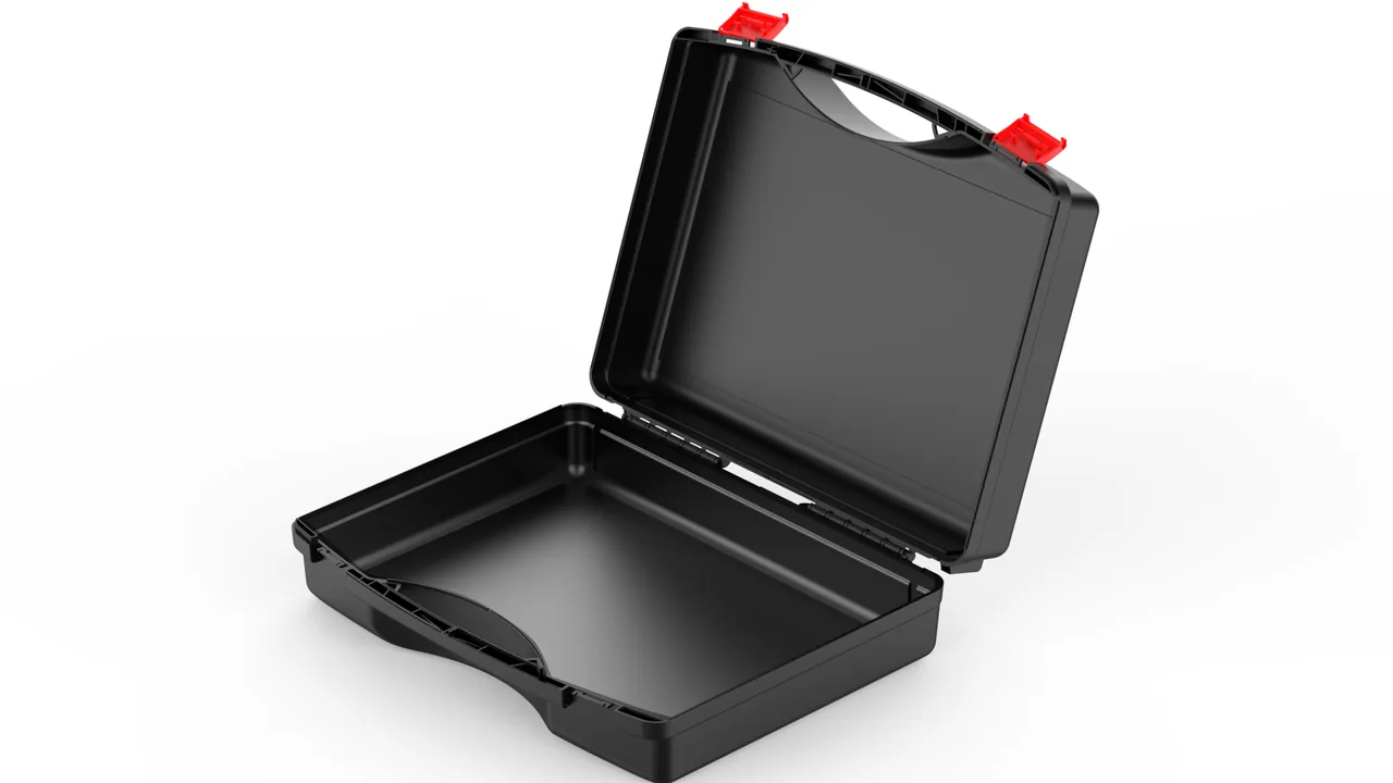
A crankshaft grinder sits at the top of the accuracy ladder on any engine production line. Its value is not in its footprint but in three numbers: the rotational accuracy of the wheel-head spindle, the locating eccentricity of the headstock chuck, and the straightness of the guideways. All three live in the micron range, and all three share a troubling property. Given a settled foundation and stable surroundings they can hold for years, yet a single careless lift or a long sea leg can degrade them permanently, with no recovery available through normal adjustment.
The JUNZHIJIA position on crankshaft grinder cases is that packaging must protect accuracy datums, not part outlines. A spindle taper, a chuck locating spigot, or a slideway face that acquires an indentation, a rust bloom or a microscopic bruise cannot be corrected afterwards by shimming, by parameter compensation, or by re-dressing the wheel. A protective case therefore has to be specified around avoiding accuracy loss rather than avoiding collision, which means controlling contact stress, controlling vibration, and controlling corrosion chemistry at the same time.
Table of Contents
- Where Crankshaft Grinder Wheel-Head Accuracy Comes From: Assembly Datums Versus Transit Risk
- Spindle Taper and Shoulder: The Contact-Stress Threshold for Irreversible Marks
- Headstock Chuck Eccentric Parts: Preserving Offset and Counterweight Pairing
- Guideway and Hardened Steel Way Surfaces: Corrosion First, Scoring Second
- Vibration-Damping Liner Design: From Static Cushioning to Resonance Avoidance
- Where VCI Rust Control Works Inside a Grinder Parts Case, and Where It Does Not
- Three-Point Support and Levelling Pad Restraint for the Wheel-Head Housing
- Headstock Spindle Housing and Chuck: Packed Together or Separately
- Tailstock Quills and Steady Rests: Restraining Concentric Components as Sets
- Hydrostatic Spindles and Motorised Spindles: Cleanliness Plus Low Vibration
- Temperature and Humidity Logging with Incoming Runout Verification
- Case Type Division: Rotomoulded Shells for Heavy Parts and Aluminium Cases for Precision Parts
- Frequently Asked Questions FAQ
- Conclusion and Related Reading
Where Crankshaft Grinder Wheel-Head Accuracy Comes From: Assembly Datums Versus Transit Risk
The wheel-head spindle of a crankshaft grinder normally runs in hydrodynamic or hybrid bearings, or in a matched set of precision angular contact bearings, with radial runout held between two and five microns and face runout under three. That figure is the sum of three contributions: the form tolerance of the spindle itself, the preload state of the bearings, and the coaxiality of the housing bores. Transit can damage the second and third, and both are hard to see.
Bearing preload is altered by shock. Rolling elements contact their raceways elastically, so an impact leaves shallow indentations whose depth need only reach a fraction of a micron to appear in the runout reading. Hydrostatic and hybrid designs are arguably more sensitive, because they carry load through a pressure field in the oil film, and sustained vibration lets the spindle micro-move against its bush, changing the clearance through fretting wear.
Housing bore coaxiality is lost through shell distortion. A large wheel-head housing is stiff in absolute terms, but if only three of its four corners are supported during transport the fourth hangs free and the housing twists. Once on site, levelling pads bring the base back to level, but the relative position of the bores has already moved.
| Transit risk | Accuracy item affected | Typical magnitude | Recoverable on site |
|---|---|---|---|
| --- | --- | --- | --- |
| Axial shock | Bearing preload, raceway indentation | 1 to 5 microns | Effectively no |
| Fretting wear | Hydrostatic clearance | 2 to 8 microns | Only by re-scraping |
| Housing twist | Bore coaxiality | 5 to 20 microns | No |
| Surface bruise | Taper contact ratio | Depends on depth | No |
| Surface corrosion | Locating face flatness | 1 to 3 microns | By regrinding, but size changes |
Reading the table makes the design intent obvious. The case must sever every load path that leads to the right-hand column, rather than simply adding wall thickness.
Spindle Taper and Shoulder: The Contact-Stress Threshold for Irreversible Marks
The spindle taper carries the grinding wheel flange and the shoulder provides axial location. Both are precision ground, usually to a surface roughness within Ra 0.2, and the taper is expected to show a contact ratio of at least eighty percent on blueing.
Indentation is governed by contact stress, not by impact energy. For the same drop event, force delivered through a sharp corner concentrates stress an order of magnitude higher than force delivered through a face that matches the taper. For hardened and ground steel, the working threshold is generally taken as sixty percent of yield strength; sustained contact stress above that begins to leave marks.
Three design rules follow. First, any liner touching the taper must make face contact rather than line or point contact, and the most dependable way to achieve that is a one-piece conical sleeve whose included angle matches the taper within half a degree. Second, the sleeve bore should carry a low-density IXPE or ultra-soft EVA facing that spreads the peak stress across the whole cone. Third, the spindle must never hang its weight on the taper. Mass should be carried on the cylindrical surface near the bearing journals or on a dedicated process support land, with the taper providing radial location only.
The shoulder follows the same logic. Its end face area is small, so an end stop that presses directly on it will coin a mark. The stop should thrust against a separate shoulder step or a process ring groove instead.
Headstock Chuck Eccentric Parts: Preserving Offset and Counterweight Pairing
The headstock chuck on a crankshaft grinder is not a general-purpose workholding device. It carries an adjustable eccentric mechanism plus counterweights, using a slider to set the offset and matched balance weights to cancel the centrifugal load that offset produces.
Transit risk here has two layers. The first is movement of the eccentric mechanism itself. If the slider shifts along its way during transport, the offset changes, and the crank radius of the ground part changes with it even when the dial indicator reading at setup looks identical. The second is the pairing between counterweight and slider. Weights are selected per offset, so once they are mixed up, rebalancing has to be redone on site, frequently requiring the whole chuck to be stripped.
The packaging answer is to lock the mechanism. Fit a removable locking block between slider and chuck body and secure it with bolts so that freedom in every direction is zero. Store counterweights in dedicated pockets labelled with the slider number they belong to. Where the chuck is heavy, consider removing it from the spindle nose and packing it separately, with a rigid cover over the flange joint.
| Component | Freedoms to restrain | Method | Common mistake |
|---|---|---|---|
| --- | --- | --- | --- |
| Eccentric slider | Radial and circumferential | Locking block plus bolts | Relying on friction alone |
| Counterweights | All | Separate numbered pockets | Tossed in the same compartment |
| Chuck flange face | All | Rigid cover | Foam laid straight onto it |
| Adjusting screw | Axial rotation | Anti-rotation clamp | Ignored entirely |
Guideway and Hardened Steel Way Surfaces: Corrosion First, Scoring Second
Both the wheel head and the work table of a crankshaft grinder travel on guideways, and guideway accuracy sets the cylindricity and waviness of the ground journal. Large machines often use hardened and ground ways or bolted steel ways. They are hard, but their impact tolerance is limited, and their edges are the most vulnerable feature.
Way surface failure follows two steps, and corrosion usually comes first. Once a rust film has formed, its hardness exceeds that of the substrate, so during handling or assembly the rust particles roll between contacting faces like abrasive grit and cut longitudinal scoring into the way. Rust control on a guideway is therefore also wear control.
Three packaging rules apply. First, the working face should be oriented upward or away from load, so that no liner presses directly on the sliding surface. Where geometry makes that impossible, apply a peelable protective film to the way and let the liner bear on the film rather than on bare metal. Second, protect the way ends with soft corner guards in EVA or engineering plastic; metal guards are counterproductive because they become the damage source in an impact. Third, tape the joints of bolted steel ways so that grit and foam debris cannot enter the seam in transit.
Machined cast iron ways also need protection from handling itself. Skin oils and fingerprints are chloride-bearing contamination. Operators should wear clean gloves, and where contact is unavoidable the surface should be re-treated with a solvent-borne rust preventive rather than wiped with a rag.
Vibration-Damping Liner Design: From Static Cushioning to Resonance Avoidance
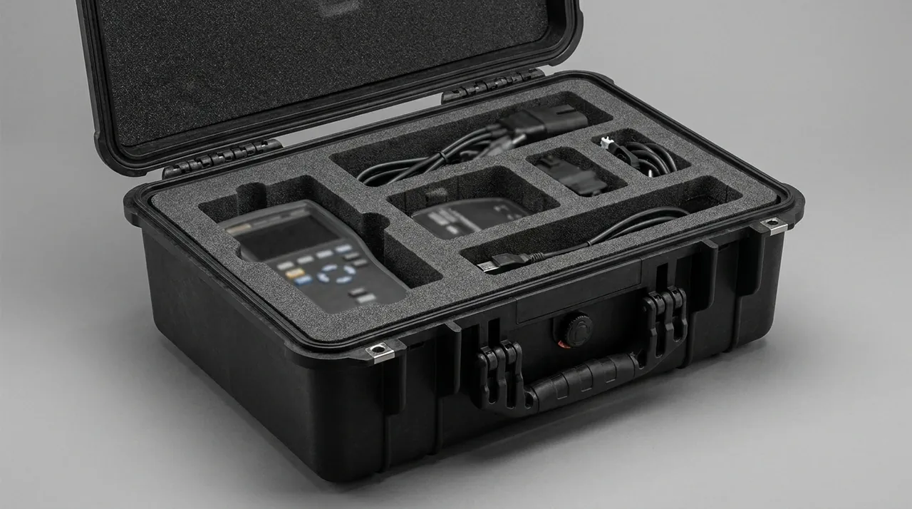
In ordinary equipment packaging a liner only has to survive a drop. In crankshaft grinder packaging it has a second job: pushing the first natural frequency of the packed assembly out of the excitation band of the transport mode.
The calculation runs in two steps. First, estimate the first natural frequency of the mass-and-spring system formed by the component and its liner. Liner stiffness depends on dynamic modulus, bearing area and thickness, and dynamic modulus typically runs twenty to forty percent above the static figure, so selecting foam from a datasheet static number is a common error. Second, compare that frequency against the transport environment: road freight concentrates energy between 3 Hz and 20 Hz, rail adds periodic impacts in the 1 to 15 Hz region, and sea freight shifts lower but lasts far longer.
In practice a first mode above 25 Hz is a comfortable target, because road excitation then falls in the isolation region rather than at resonance. Raising the frequency means stiffening the liner or reducing the packaged mass through separate packing; lowering it means the opposite. For a heavy wheel head the usual choice is the stiffer route, since high stiffness also limits displacement, which is what micron-level accuracy needs.
| Liner material | Dynamic modulus tendency | Rebound damping | Suitable location | Note |
|---|---|---|---|---|
| --- | --- | --- | --- | --- |
| EPE | Low | Moderate | Heavy-part base and ends | Inexpensive, creeps under long load |
| High-density EVA | High | Low to moderate | Precision supports, wedging | Minimal compression set |
| Microcellular PU | Medium | High | Damped critical locations | Costly, tear resistant |
| Rubber damper pad | Medium to high | Very high | Under spindle housing | Needs ageing and oil resistance |
Using one foam throughout is rarely optimal. A better approach is stiffness zoning: high-density EVA under the load paths to limit displacement, EPE at the sides and ends to absorb impact, and local pockets of microcellular polyurethane at the sensitive locations that need damping.
Where VCI Rust Control Works Inside a Grinder Parts Case, and Where It Does Not
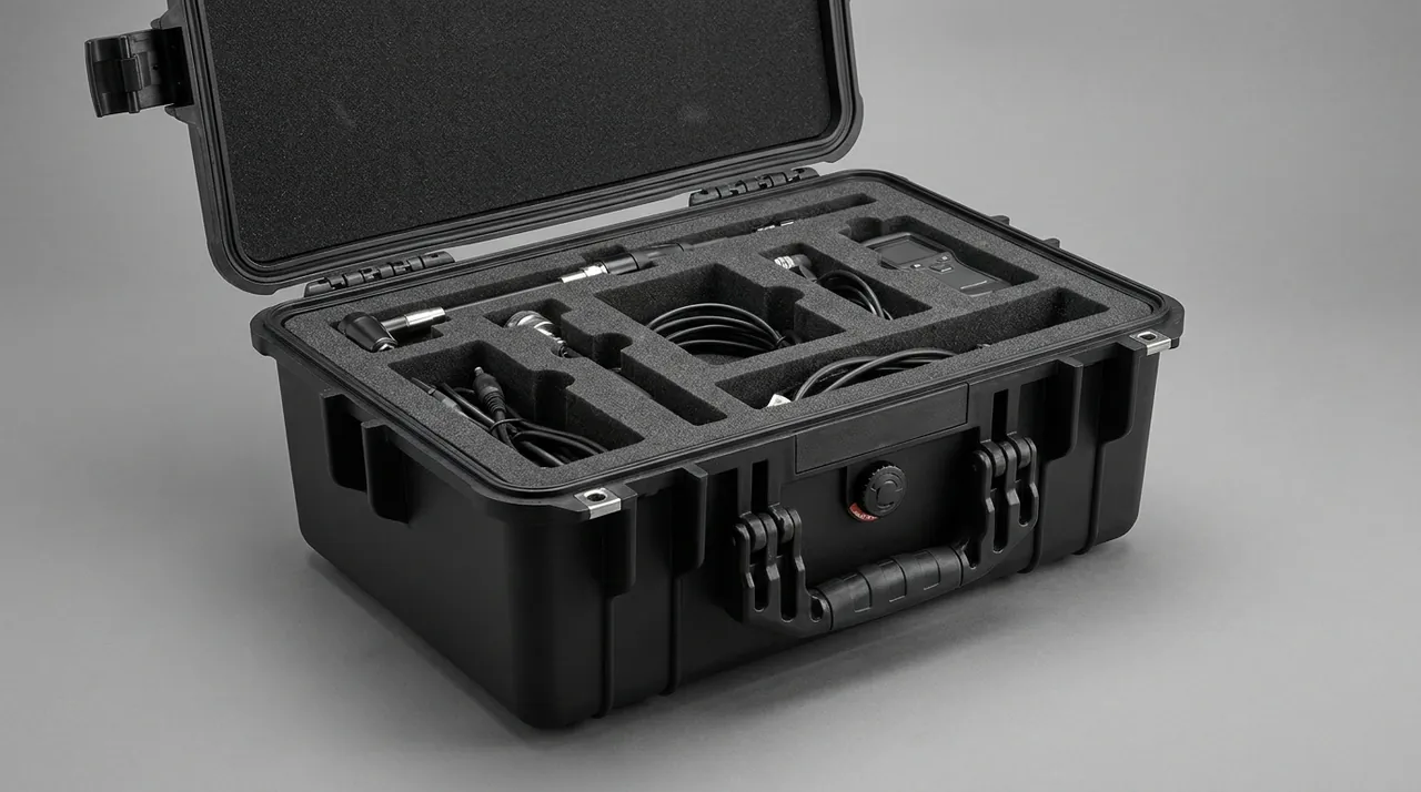
Vapour-phase corrosion inhibitor material releases inhibiting molecules that adsorb on metal surfaces as a monomolecular layer and block the water film from oxygen. Inside a closed volume it works well, but several boundaries have to be respected, because used outside them it can do harm.
First, VCI needs a closed volume to hold concentration. A case with an aged gasket, or one shipped without a breather valve so the internal atmosphere keeps exchanging, will dilute the inhibitor and sharply reduce its effective radius. VCI complements sealing; it does not replace it.
Second, effective distance is limited. Performance is best within about a metre, so a large wheel-head case needs sachets or film pockets distributed at different heights and corners rather than a single sheet on the floor.
Third, compatibility with non-ferrous metals must be confirmed. Amine-based formulations protect steel and cast iron but can discolour or attack copper, zinc and cadmium plating. Crankshaft grinder assemblies routinely carry bronze bearing shells, chrome plating and aluminium nameplates, so either select a compatible formulation or isolate those areas locally.
Fourth, VCI only works on a clean surface. Fingerprints, chips and water marks prevent the inhibitor from forming a continuous film, and pitting then develops beneath the contamination. The correct order is clean, dry, optionally apply a thin oil film, wrap in VCI film, then close the case.
| Material | VCI compatibility | Handling |
|---|---|---|
| --- | --- | --- |
| Cast iron, carbon steel | Good | Direct use |
| Precision-ground alloy steel | Good | Combine with peelable film |
| Bronze bearing shells | Formulation dependent | Verify before use |
| Chrome plating | Moderate | Isolate locally |
| Aluminium parts | Formulation dependent | Avoid long contact |
Three-Point Support and Levelling Pad Restraint for the Wheel-Head Housing
A wheel-head housing usually leaves the factory with levelling pads or adjusting bolts. Left free in transit, these pads rotate, migrate and sometimes drop off. Tightened hard, they impose local stress into the housing base.
The workable arrangement is three-point support with the remaining pads backed off. Three points define a plane uniquely and introduce no over-constraint, while the other levelling positions are set to a clearance of 0.2 to 0.5 mm so they carry nothing. The three live points should sit as close as possible to the main ribs or the foundation bolt holes, so the load travels directly into structure.
Implementing three-point support needs a dedicated pad set. Pad height is machined to the actual base of the housing, the top face carries high-density EVA for compliant contact, and the underside has a spigot that keys into the floor liner. Once positions are fixed, mark them permanently inside the case so that subsequent shipments use the same points and the loading state does not drift between batches.
For very heavy wheel heads, three points are not enough, and auxiliary supports are added with pads set slightly lower so only three carry load in normal handling. That three-plus-auxiliary pattern applies equally to the work table and the bed when they ship separately.
Headstock Spindle Housing and Chuck: Packed Together or Separately
Whether to ship the headstock spindle housing with the chuck attached is the most common packaging disagreement on this machine. Both routes carry a cost.
Together, the assembly keeps the factory set-up intact, so the spindle-to-chuck interface is never disturbed and installation is direct. The penalties are high total mass, a centre of gravity pulled towards the outboard chuck, a requirement for extra counterweight pockets and a thicker floor support, and the fact that the protruding chuck becomes the leading edge in any drop or tip-over.
Separately, the centre of gravity tightens, smaller cases can be used, and the chuck can be given a higher protection class in its own case. The penalty is that reassembly requires re-locating the chuck, and on a crankshaft grinder that relocation usually involves recalibrating the eccentric mechanism, which many sites are not equipped to do.
One criterion settles the decision: does the site have the means and the skilled staff to recalibrate a chuck? If yes, separate packing is preferred. If the site only performs a bolt-on installation, pack the assembly together and strengthen three things: a thicker end buffer on the chuck side, counterweight pockets positioned so the combined centre of gravity falls near the case centre, and a removable hood over the protruding chuck. When packing separately, the flange joint on the spindle nose must get a rigid cover with a soft inner face, and the case should include the bolt torque figures and tightening sequence.
Tailstock Quills and Steady Rests: Restraining Concentric Components as Sets
Tailstock quills, steady rests and follow rests all serve the same function: aligning something to the same rotational centre as the headstock spindle. Their shared transit risk is that the relative position of a matched set gets disturbed.
The critical feature of a quill is its Morse taper bore. A single mark on that bore raises the runout of any centre fitted into it. The quill should therefore be stood upright or held horizontally in a machined cradle, with a soft protective plug in the bore. The plug must be plastic or timber, never metal, and no liner may contact the bore wall.
Steady rest fingers should be removed and packed individually, or pinned in position. The adjusting screws are slender and vulnerable to side impact, so they should be wound in close to the body to shorten the overhang before packing. Follow rests follow the same rule, with guide wheels removed and placed in their own pockets.
| Component | Fragile feature | Dominant failure | Restraint |
|---|---|---|---|
| --- | --- | --- | --- |
| Tailstock quill | Morse taper bore | Marking, corrosion | Soft plug, upright |
| Steady rest body | Guide faces | Impact damage | Horizontal, faces up |
| Support fingers | Tip radius | Chipping | Removed, individually packed |
| Adjusting screws | Threaded section | Bending | Wound into retracted position |
| Follow rest wheels | Outer diameter | Scoring | Dedicated pocket |
Hydrostatic Spindles and Motorised Spindles: Cleanliness Plus Low Vibration
Modern crankshaft grinders increasingly use hydrostatic or hybrid spindles and motorised spindles. Both raise the packaging difficulty a notch, because cleanliness and low vibration are demanded simultaneously.
A hydrostatic bearing depends on precision restrictor orifices and an extremely thin oil film, often ten to twenty microns. Any solid particle entering the film scores the journal. Before packing, every oil port must be plugged with a capped plug carrying an O-ring, and all exposed oil and air ports on one assembly should use the same colour plug so that reinstallation can be checked at a glance. Liners in contact must not shed, so foam dust emission should be tested, or the spindle wrapped in a clean bag first.
Motorised spindles bring a different concern: rotor balance and bearing protection. Transit vibration does not disturb balance directly, but it produces micromotion in the bearing raceways that shows up as elevated noise at first start-up. The spindle should be packed in its own case with a damping layer, tuned so the first mode sits above the road excitation band. Where possible the rotor should be secured with a transport locking sleeve so it cannot sit at the same angular position for the whole journey.
Cooling jackets deserve attention too. Residual water freezing in a water jacket expands and can crack it, so the jacket must be blown dry with compressed air and the inlet and outlet plugged. This step is most often skipped in humid or cold regions, and most often in winter shipments.
Temperature and Humidity Logging with Incoming Runout Verification
Incoming acceptance of precision parts cannot rely on a visual walk-around. For crankshaft grinder components, fix the process into three steps: record, measure, judge.
Recording means putting a temperature and humidity logger inside the case to capture the full transit profile. The curve serves two purposes. It shows whether condensation occurred, by comparing the temperature trace against the dew point trace, and it shows whether the case experienced prolonged high humidity, which determines whether rust treatment is needed immediately. The logger belongs close to the packed component, not taped to the lid.
Measurement covers spindle radial and face runout, measured on a purpose-built fixture or on site with a magnetic base and a standard test bar; guideway straightness sampled with a precision level or laser interferometer; chuck locating spigot radial runout; and taper contact ratio checked with blueing or a contact print. Each result is compared item by item against the factory record rather than simply passed or failed.
Judgement needs agreed tolerances. A technical agreement should state that radial runout may not increase by more than 1.5 microns over the factory value, that guideway straightness may not degrade by more than three microns per metre, and that taper contact ratio may not fall by more than ten percentage points. Anything beyond those limits is classified as transit damage and enters the claim and repair route.
Case Type Division: Rotomoulded Shells for Heavy Parts and Aluminium Cases for Precision Parts
The component range on a crankshaft grinder spans several orders of magnitude, from a wheel-head housing weighing hundreds of kilograms to a chuck slider weighing a few. No single case type covers all of them, so the sensible approach is to divide by mass and accuracy class.
| Component class | Typical mass | Case type | Liner scheme | Key requirement |
|---|---|---|---|---|
| --- | --- | --- | --- | --- |
| Wheel-head housing | 200 to 1500 kg | Rotomoulded or steel-frame timber | Stiffness zoning plus three-point support | Bending resistance, forklift handling |
| Headstock spindle housing | 100 to 600 kg | Rotomoulded | Full EVA encapsulation | Centred centre of gravity |
| Chucks and eccentric parts | 20 to 120 kg | Rotomoulded or injection moulded | EVA compartments plus locking blocks | Anti-loss, anti-displacement |
| Guideways and keep strips | 5 to 40 kg | Aluminium or injection moulded | Soft corner guards plus peelable film | Anti-score, anti-rust |
| Hydrostatic and motorised spindles | 10 to 80 kg | Aluminium | Clean bag plus damping liner | Cleanliness, low vibration |
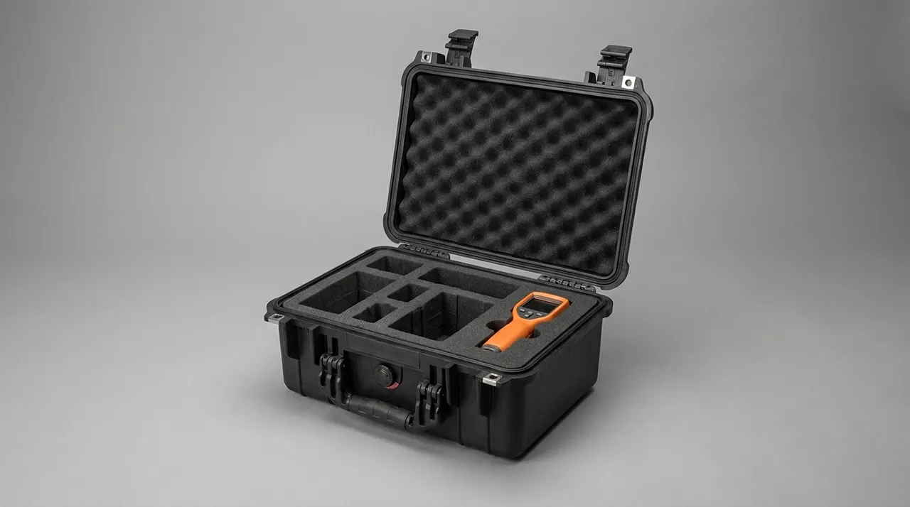
Rotomoulded shells suit heavy parts because wall thickness is uniform, impact behaviour is good, and deep cavities with ribs are practical. Aluminium cases suit precision parts because they are dimensionally stable, accept fine liners, and present well as machine-attendant boxes. Where both types ship on one pallet, stack with care: the base of a rotomoulded case must never rest directly on the lid of an aluminium case.
On process selection for the shells themselves, the trade-off between the two moulding routes is set out in injection moulding versus rotational moulding for cases, and liner selection follows the comparison of foam material options for protective cases. These tolerances must then be proven in transit. Vibration exposure is assessed with the method in transport vibration testing for cases, and the corrosion side is controlled with the practices in rust prevention for metal toolboxes and validated using salt spray corrosion testing.
Frequently Asked Questions FAQ
Q: Does a crankshaft grinder wheel-head spindle really lose accuracy in transit, and is there data behind that claim?
A: Yes, and the mechanisms are well defined. Accuracy loss runs through three routes: raceway indentation from shock, where a depth of a fraction of a micron already shifts the runout reading, with measured increases typically between two and five microns; fretting wear in hydrostatic or hybrid bearings under sustained vibration, which changes clearance and therefore load capacity and stiffness; and housing twist from uneven support, which alters bore coaxiality by as much as five to twenty microns. None of these recover once the shipment ends. The awkward part is that they often look normal during a no-load spin check and only appear as waviness when a crank journal is actually ground, so the fault is frequently misdiagnosed as a grinding parameter problem and weeks pass before the real cause is found. Recording runout before dispatch and again on arrival is the only reliable way to separate transit damage from a machine that was already drifting.
Q: Why can a spindle taper not simply be held with foam, and how critical is contact stress?
A: Because indentation is governed by contact stress rather than impact energy. In the same drop event, force delivered through a sharp corner or a line contact can produce local stress an order of magnitude higher than force spread over a matching face. For hardened and precision-ground steel, working practice treats sixty percent of yield strength as the point beyond which visible marks begin to form, and a light mark on a spindle taper is enough to destroy the contact ratio, so that the wheel flange runs with face runout after fitting. The correct solution is a one-piece conical sleeve liner whose included angle matches the taper within half a degree, with a low-density IXPE or ultra-soft EVA facing on the bore to level the peak stress. Crucially, the taper must not carry the spindle mass, which belongs on a process support land near the bearings. Weight hanging on a taper also makes the sleeve harder to fit without forcing it.
Q: What is most often overlooked when packing an eccentric headstock chuck?
A: The pairing between the eccentric slider and its counterweights. The offset is set by where the slider sits along its way, and counterweights are selected for that offset. Many operations simply lift the whole chuck into a case and strap it down, with neither a slider lock nor any numbered storage for the weights. Vibration then walks the slider a fraction of a millimetre, changing the offset; more often still, the weights are removed and dropped into the same compartment, so at destination they are refitted to the wrong slider. The result is a balancing job that the site is rarely equipped to perform, since it needs a balancing machine and trial weights. The reliable treatment is a removable locking block bolted between slider and chuck body, plus individually labelled pockets for each counterweight. A photograph of the slider position taken before packing costs nothing and settles any later argument about whether the offset moved in transit or was set incorrectly at the factory.
Q: Is it enough to put VCI film in the case, and what are the limits of that approach?
A: No, and using it outside its limits can make matters worse. VCI has four boundary conditions. It needs a reasonably closed volume to maintain concentration, so an aged gasket or a missing breather valve dilutes the inhibitor and shortens its effective radius sharply. Its effective distance is limited, so a large wheel-head case needs sachets or film pockets distributed at different heights and corners rather than one sheet on the floor. Its compatibility must be confirmed, because amine-based formulations can discolour or attack bronze bearing shells, chrome plating and some aluminium alloys, all of which appear on grinder assemblies. Finally, it only works on a clean surface, since fingerprints, chips and water marks block film formation and become pitting sites underneath. Clean, dry, optionally oil lightly, then wrap and close the case. A humidity indicator card inside the case turns the whole argument into something an operator can read in two seconds.
Q: Why is three-point support used under a wheel-head housing instead of more contact points?
A: Three points define a plane uniquely and introduce no over-constraint, whereas four or more supports can never be made exactly equal in practice, so one point always ends up hanging or overloaded and the housing bends locally over that support. Bore coaxiality in a crankshaft grinder wheel-head housing is highly sensitive to bending, and a few microns of distortion can amplify into a clearly visible runout deviation after assembly. The accepted engineering pattern is therefore three primary points plus several auxiliary points. The three primaries sit near the main ribs or foundation bolt holes, with pads machined to the true base height and a high-density EVA face for compliant contact. Auxiliary pads are set 0.2 to 0.5 mm lower so they engage only under heavy shock. Once positions are established, mark them permanently so later shipments repeat the same loading state. Pad height should be re-checked whenever a different housing variant is packed.
Q: Should the headstock spindle housing and the chuck be packed together or separately?
A: One criterion decides it: whether the site can recalibrate a chuck. A crankshaft grinder chuck carries an eccentric adjustment mechanism, and refitting it requires resetting the offset and rebalancing, which takes dedicated gauges, trial weights and experienced staff. Where those resources exist, separate packing is preferable, because the centre of gravity is tighter, individual masses are lower, and the chuck can be given its own case with higher protection and thicker end buffers, without a protruding chuck forming the leading edge in a drop. Where the site only bolts the unit back in place without recalibration, pack them together and strengthen three details: a thicker end buffer on the chuck side, counterweight pockets arranged so the combined centre of gravity falls near the case centre, and a removable hood over the protruding chuck. Separately packed, the flange joint needs a rigid cover plus documented torque and tightening sequence. Either way, the decision should be written into the technical agreement so that a later shipment does not quietly reverse it.
Q: At incoming inspection, how do you prove that accuracy was lost in transit rather than being out of specification from the start?
A: By comparing against the factory record item by item instead of checking pass or fail. Ask the builder to ship a factory inspection record covering at minimum spindle radial and face runout, guideway straightness, chuck locating spigot runout and taper contact ratio. Then repeat those measurements under equivalent conditions on arrival: runout with a standard test bar, magnetic base and dial indicator; straightness sampled with a precision level or laser interferometer; contact ratio with blueing to reveal the print area. Write the limits into the technical agreement, for example a radial runout increase of no more than 1.5 microns, guideway degradation of no more than three microns per metre, and a contact ratio drop of no more than ten percentage points. Read the logger as well, so condensation history supports the claim. Without a logger, a claim usually turns into a debate about the weather rather than a technical finding.
Q: What level of cleanliness is required when packing precision spindles and hydrostatic assemblies?
A: A level consistent with a precision assembly shop, meaning control of three items. First, control the dust source: ordinary PE or EPE foam sheds particles under vibration, so the immediate wrap around a hydrostatic spindle must be a clean bag, with outer liners either low-shedding grades or themselves sealed. Second, plug every oil and air port, because hydrostatic restrictor orifices and oil films run ten to twenty microns and any solid particle entering them scores the journal; plugs should carry O-rings and share a single colour for easy verification on refit. Third, water: residual coolant in a motorised spindle jacket freezes and expands in cold weather and can crack the jacket, so blow it dry with compressed air and plug the ports before shipping. Those three points remove most contamination risk. A documented clean-packing procedure matters as much as the materials, because the last person to handle the spindle sets its condition.
Conclusion and Related Reading
Crankshaft grinder packaging transfers accuracy datums, not just hardware. Wheel heads fear contact stress and resonance, headstocks fear mechanism movement and mismatched parts, guideways fear corrosion followed by scoring.
Related Reading