

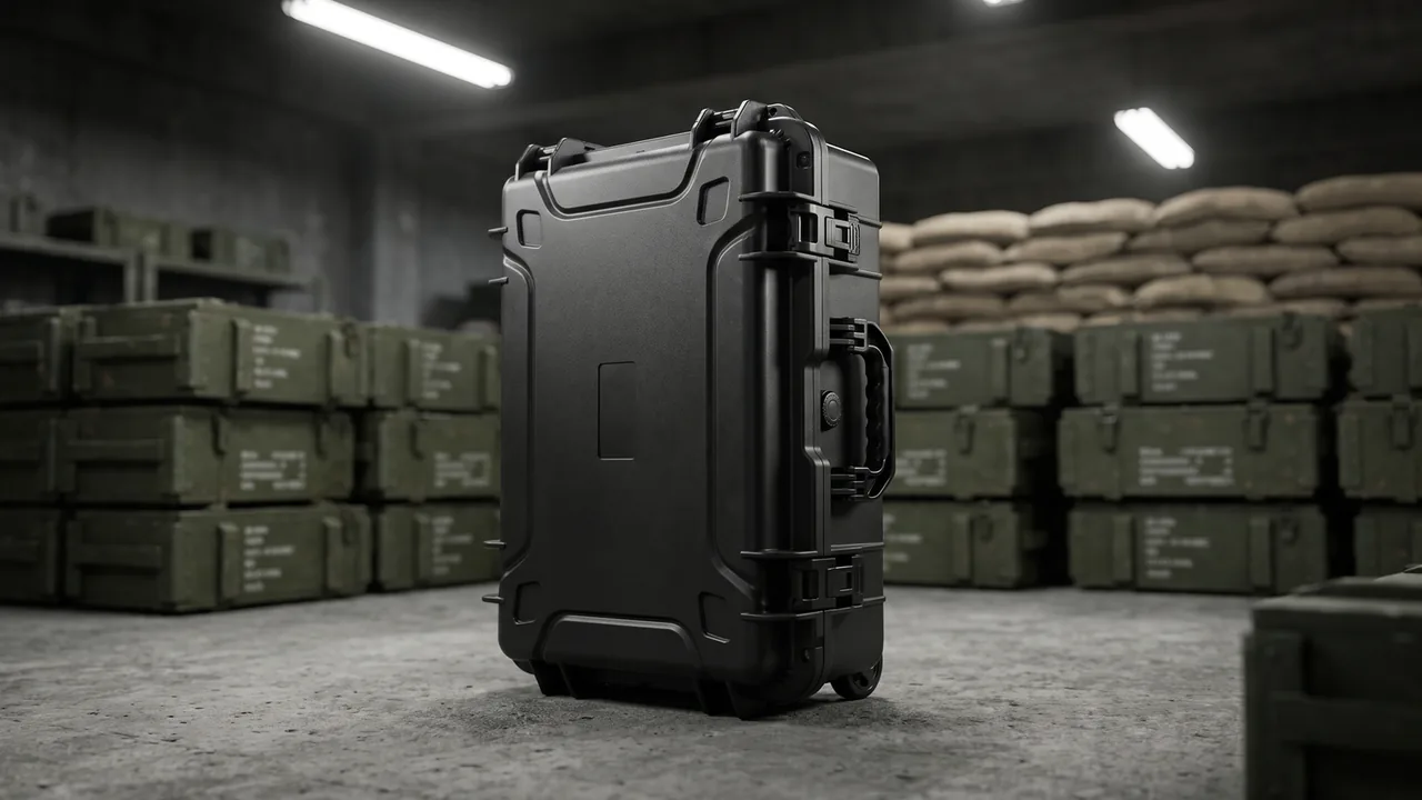
Putting a multirotor aircraft into a case looks like nothing more than finding the right box. In practice it is an engineering problem that begins with a three-dimensional envelope. An aircraft is not a regular solid: it has an open attitude and a folded attitude, outboard arms, an underslung gimbal, fragile landing gear, and antennas. The case must contain all of it while preventing movement, mutual crushing, moisture ingress, and vibration damage during transport, handling, and stacking. The drone case emerged as a distinct product category precisely because the liner logic of a general-purpose protective case cannot answer the specific question of what this particular airframe envelope actually looks like.
This article approaches the subject from the design and manufacturing side of protective containers. It covers airframe fit methodology, insert surveying and positive location, zoning for airframe and payload, container-level isolation and temperature control for the battery bay, sealing and damping, materials and processes, and inspection. Standards referenced here are cited as test methods only and do not represent certification. JUNZHIJIA's most frequent advice on these projects is simple: send us a real aircraft before discussing case dimensions, because the catalogue outside dimensions and the actual packed envelope often differ by more than buyers expect.
Why a Drone Case Cannot Simply Reuse a General-Purpose Protective Case
A general-purpose protective case starts from the premise of fitting and protecting, and its insert is usually a single block of foam whose density and thickness provide cushioning. That logic works well for regular, rigid objects, but it fails an aircraft in three ways. First, the envelope is irregular: arms, landing gear, and gimbal create outboard structures in three directions, and a monolithic foam block surrounds them without providing directional constraint where it matters. Second, mass is unevenly distributed: the center of gravity usually sits toward the battery side, so on impact the airframe rotates inside its foam cavity and strikes the cavity wall. Third, attitude is variable: many airframes require folding arms, stowing propellers, or removing the gimbal before packing, and an insert designed for one attitude will not accept another.
A drone insert therefore behaves more like a custom support system than a carved foam recess. Positive location and load bearing belong to rigid structure; cushioning belongs to elastic material, and the two roles stay separate. The direct benefit is that displacement during transport is confined to a designed band instead of accumulating as a slow swing inside a foam cavity. Related general requirements are discussed in What Are the Special Requirements for a Drone Protective Case: Storage Essentials for Aircraft and Accessories.
Airframe Fit Starts with Envelope and Folded Attitude
The first step in fitting is replacing outside dimensions with the packed envelope. Outside dimensions describe the maximum envelope in one attitude. The packed envelope is the space the aircraft occupies in its packing attitude, plus the necessary handling clearance, plus insert thickness, plus the locating structure. Buyers who quote only a manufacturer's length, width, and height frequently receive a case that either will not accept the aircraft or is far too hollow inside to protect it.
The second item to confirm is the folded attitude. Common options are stowing propellers without folding arms, folding arms with propellers attached, and folding arms with the gimbal removed, and each produces a very different envelope. A folded configuration is more compact but demands tighter control of the arm joints, because a folded joint is a latent degree of freedom and sustained vibration slowly opens it until it presses against adjacent structure. Designers normally add anti-rotation features or elastic preload at the joint to lock that freedom out.
The third step is clearance. The insert cavity cannot touch the airframe with zero gap, or every removal scrapes the shell, yet too much gap lets the airframe shift. The practical method is matched support at the critical load points, such as the belly, arm roots, and landing gear, with two to five millimetres of handling clearance in non-load-bearing areas. The exact figure follows retrieval frequency and operator habit: high-cycle operations should err on the generous side, while long-term storage can be tighter.
Insert Design: From 3D Survey to Positive Location
Insert design progresses from data to structure. The data stage uses 3D scanning or manual surveying to turn the aircraft surface in its packing attitude into a model that can be cut. The structure stage converts that model into a layered insert scheme. A common layering approach is base plate for load bearing, side walls for location, and top for preload. The base plate matches the belly and landing gear and carries vertical load. The side walls locate the arms and fuselage sides and carry horizontal load. The top uses an elastic preload block to hold the airframe gently so it cannot bounce.
Materials usually come from three families: cross-linked polyethylene, ethylene-vinyl acetate, and polyurethane. Cross-linked polyethylene offers good resilience, weather resistance, and moderate cost, suiting large base plates. Ethylene-vinyl acetate provides better feel and dimensional stability, suiting precise locating walls and visible components. Polyurethane accepts density adjustment and suits cushioning layers that need a specific stiffness curve. The core principle is to use different hardness in different regions rather than one material throughout. Cutting and layering are described further in Foam Insert Design for Drone Cases by Airframe Type.
Positive location is the part most often simplified. Relying on foam friction alone fails under sustained vibration, because repeated micro-movement polishes the foam surface and reduces friction. A more reliable approach adds rigid or semi-rigid locating elements: a locating block under each arm, a retaining edge at the landing gear, and a locating pin at the belly. These elements lock the airframe in place while the foam only cushions, rather than carrying the locating duty.
Zoned Protection for Airframe, Propellers, and Gimbal
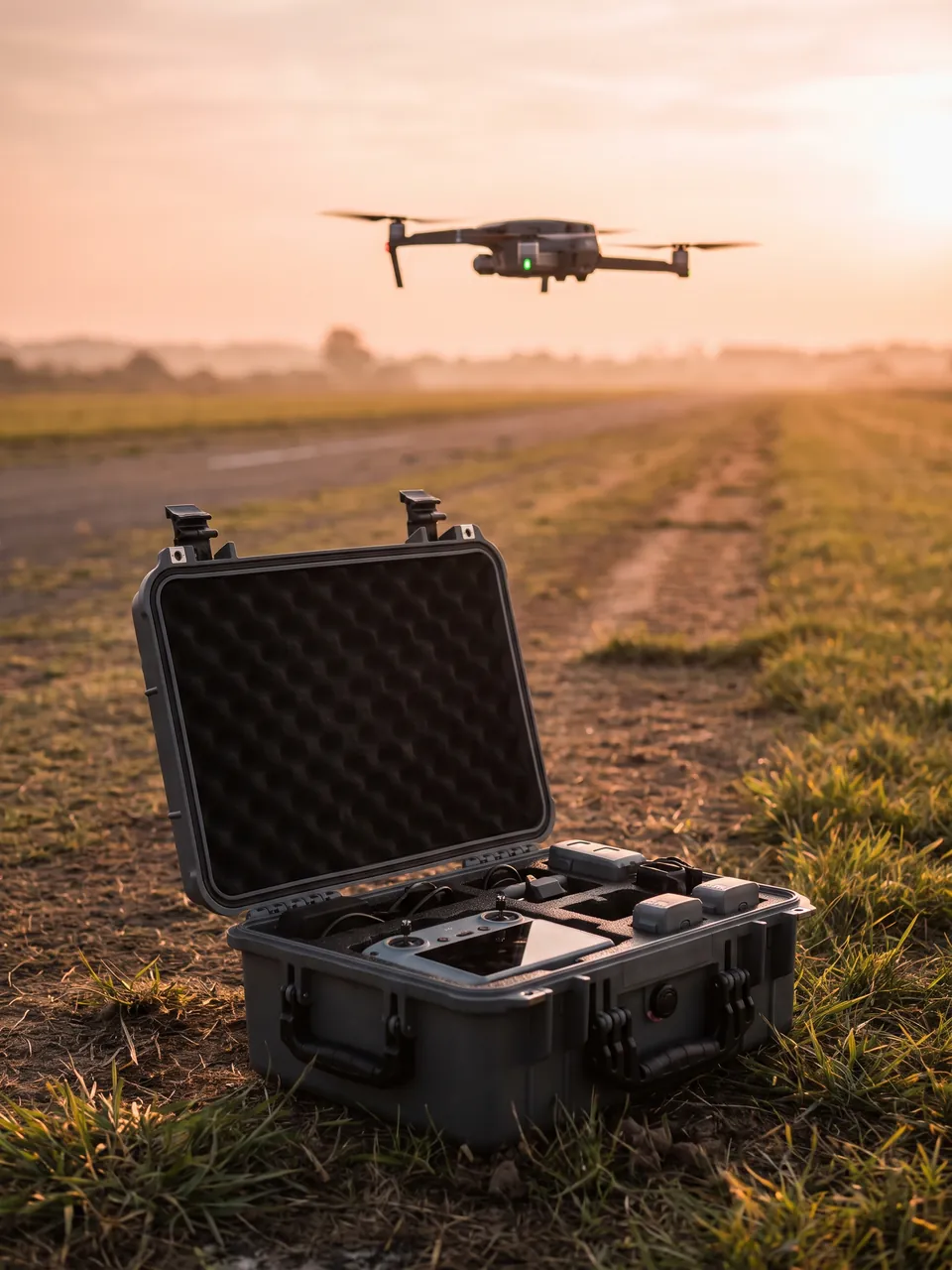
A complete flight system packs at least four categories of equipment: the airframe, the propellers, the gimbal and lens, and accessories. Their protection requirements differ completely, and mixing them in one cavity is a common design flaw. The airframe needs full support and location, propellers need protection from bending and scratching, the gimbal and lens need vibration isolation and freedom from load, and accessories can be arranged by rule.
Propeller protection is mainly about bending resistance. Propellers are thin and long, and their worst hazard in transit is being bent by a heavy object or nicked by hard material. The sound approach gives propellers a dedicated flat cavity, laid flat with cushioning above and below so stacking pressure never bears directly on the blade surface. If the aircraft is packed with propellers attached, side pockets for the blades let the case wall act as a rigid backing.
Gimbal and lens protection is about carrying no load at all. The gimbal is a cantilever structure, and any pressure applied to its housing travels into motors and bearings. Design normally places the support points for that region on the belly and top structure, leaving the gimbal suspended with clear space around it and only flexible end stops at the limits of travel. The lens needs protection for its optical surface, so the design leaves clearance ahead of the lens and adds a removable soft cover, keeping liner material off the glass. Optional layouts for imaging gear appear in Drone Accessory Cases: Controller, Propellers, Aerial Gear and Ground Station.
Restraining Landing Gear, Antennas, and Video Modules
Landing gear is the primary load path between airframe and case, and it demands the most careful treatment. The placement of support decides the vertical attitude of the airframe. Supplying support at the tips of the gear means impact travels up the gear into the airframe attachment, which easily damages structure. Supporting the belly instead means the gear takes compression during ordinary handling. Common practice is dual support: the belly carries static and stacking load, while flexible stops at the gear tips participate only during impact.
Antennas and video modules are outboard, fragile items. Antennas typically fail by snapping at the root, usually because they swing in transit or take a lateral squeeze. A flexible guide channel at the antenna position lets it bend in one controlled direction instead of taking load from any direction. Video modules normally carry heat sinks and connectors, and packing should keep connectors free of load while orienting them toward the access opening so insertion and removal stay easy.
Heat is the other consideration in this region. Some video and computing modules retain heat after power-down, and if they sit tight against foam with poor ventilation, that heat is trapped in the cavity. Leaving an air cavity near the module and avoiding low-density foam that takes a permanent set at temperature is the sound approach. For cases used in rapid field redeployment, the cooling path after the lid opens also deserves thought, so heat can escape naturally.
Battery Bay: Container-Level Isolation and Temperature Control
Inside a drone case, the battery should be treated as an independent unit, and the design focus is container-level isolation and temperature control rather than how the cell itself works. Isolation has two layers. Physical isolation places the battery in its own cavity, separate from airframe, propellers, and gimbal, so nothing crushes anything else and any local issue does not reach the whole aircraft. Thermal isolation uses cavity walls, dividers, and air gaps to separate the battery cavity from the others in terms of heat flow.
On temperature control, the container can do several things. It can leave a pocket in the battery cavity for phase-change material or an insulating pad. In cold conditions it can use low-conductivity case material or add an insulating liner to slow the temperature drop. In hot, sun-exposed conditions it can avoid prolonged direct sunlight or use a light-coloured exterior to reduce radiant heat gain. The shared aim is a relatively stable temperature band during transit rather than precise control.
Securing the battery matters just as much. A battery pack is usually heavy and often defines the case center of gravity, so it must not move under impact or vibration. Common practice is a matched support in the cavity floor, locating blocks on the walls, and an adjustable strap or plate limiting vertical bounce. The access opening should allow one-handed loading and unloading with one hand free, because swapping packs is routine work. When packs travel separately, the independent-cavity thinking described in Isolated Transport and Isolation Design for Drone Battery Cases applies.
Stowing the Controller, Spare Propellers, and Ground Accessories
In a full field kit, everything except the airframe often occupies a surprising volume. The controller, spare propellers, spare packs, chargers, cables, tools, and small ground devices will end up jammed into the airframe cavity unless they have defined homes, competing for space and adding crush risk.
Controller protection centers on screen and sticks. Sticks are outboard precision parts that bend or jam easily in transit, so a recess or a protective cap belongs at the stick position. The screen needs isolation from hard objects, usually a flexible pad. Spare propellers should lie flat in their own compartment, away from the airframe and other hard items. Chargers and cables must not let prongs pierce adjacent parts, which a separate soft pouch or compartment solves.
A practical rule is to arrange items in order of use: the battery and controller come out first, the airframe last. That sequence shortens preparation noticeably and reduces the bumping that comes from digging around inside a case. When ground-station hardware is large relative to the airframe cavity, a split-case approach is better, letting the ground equipment travel in its own container rather than sacrificing the airframe's cushioning volume to keep everything in one box.
Sealing, Pressure Equalization, and Moisture Control
A drone case faces rain, snow, dust, day-night temperature swings, and humid heat. Sealing aims to keep water and particles out while preventing persistent moisture from being trapped inside. The gasket is the critical part, commonly made of silicone rubber, EPDM, or thermoplastic elastomer. Selection follows operating temperature range, ozone and UV resistance, and compression set behaviour. Silicone stays stable across a wide temperature band, EPDM offers good weather resistance, and thermoplastic elastomer costs less but takes a larger permanent set.
The pressure equalization valve is a part many users overlook. When a case goes through air freight, mountain transfer, or sudden cooling after sun exposure, a noticeable pressure difference develops across the shell. If the seal is fully rigid, that difference loads the sealing face, can deform it locally and cause weeping, and makes the lid hard to open. The valve allows gas exchange under slow pressure differences while staying closed during rapid immersion. Selection should consider its opening differential and water resistance, matched to the overall protection target.
Moisture is the priority for long-term storage. Even a waterproof case traps the moisture carried in at packing time, which then condenses. Common countermeasures include a replaceable desiccant cartridge, a hygroscopic liner on the inner wall, and drying the aircraft and accessories before packing. For equipment stored long-term in humid regions, leaving a mounting point for a humidity indicator or data logger makes periodic checks practical. Systematic sealing judgment is covered in Waterproof Rating and Immersion Verification for Drone Cases.
Vibration Damping: Giving Precision Payloads Room to Move
Damping is fundamentally about giving the payload room to travel. Impact energy must be absorbed through the controlled deformation of some medium, and if the payload is clamped rigidly, that energy arrives as high acceleration directly into the airframe and payload. Drone cases usually damp in two stages. The first stage sits between case and ground and is handled by shell material and external cushioning pads. The second sits between payload and case and is handled by the elastic layers of the insert.
The two stages must be tuned together. The first stage has a long stroke and low stiffness, suited to absorbing larger events such as handling drops. The second has a shorter stroke and relatively higher stiffness, suppressing sustained vibration and minor impacts. If both stages are very soft, the payload moves a long way inside and risks striking neighbouring structure. If both are very stiff, impact passes straight through. Engineering practice fixes the allowable acceleration for the airframe first, then works back to insert hardness and thickness, and finally checks that shell deflection stays elastic during a drop.
The dynamic behaviour of materials is where damping design most often goes wrong. A foam's cushioning depends strongly on density, thickness, and temperature, and the same material stiffens and absorbs less when cold. A case intended for cold environments must therefore be validated at low temperature rather than inheriting room-temperature data. Foam also takes a permanent set under long compression and loses resilience gradually, which is precisely why inserts need periodic replacement.
Shell Materials and Molding Processes
Drone case shells are usually chosen among three options: rotomolded polyethylene, injection-molded engineering plastic, and composites. Rotomolding produces a seamless monolithic shell with good impact performance and accepts molded-in metal inserts for hinges and latches, which suits medium and large cases. Its weaknesses are wall-thickness consistency depending on process control and lower cosmetic precision than injection molding. Injection molding suits small and medium cases, delivers high dimensional accuracy, and allows complex ribs and snap features, with higher tooling investment but lower unit cost at volume. Composites serve applications that are acutely weight-sensitive, gaining high specific stiffness from sandwich construction and fibre layup at high cost and poor repairability.
Structurally, three regions need reinforcement: the four corners, the hinge mounting area, and the latch mounting area. Corners are the most likely ground contact in a drop and normally get thickened zones or metal protectors. Hinge and latch regions take repeated cycling and sealing preload, so they need local thickening or metal inserts to prevent mounting holes deforming after long service and breaking the seal. Rib layout should follow the primary load directions and align with insert support points, so load travels the shortest path into the wall.
Process consistency deserves particular attention in volume procurement. Rotomolded wall thickness and shape vary between batches from the same mold, so an insert fitted to one measured shell can be too tight or too loose in the next. The sound approach writes internal dimension tolerances into the specification and requires the insert design to be checked at both tolerance limits, using adjustable locating elements to absorb the variation where necessary.
Casters, Trolley Handle, and Carrying Options
Drone work is characterized by moving from vehicle to operating point, a distance that may be tens of metres or several hundred metres of mountain trail. Carrying method therefore trades off between casters, a telescoping handle, and shoulder carry. Wheels plus a handle suit hard surfaces and longer distances and save real effort, but demand enough base stiffness to react the bending moment the handle imposes. Shoulder and backpack straps suit rough ground and distribute weight across the back, at the cost of sustained physical effort.
Caster selection is closely tied to case weight. A single-aircraft case with its airframe usually stays within a manageable range, where two fixed wheels plus two swivel wheels suffice. When the case also carries several packs and ground equipment, total weight rises and larger wheels with higher per-wheel ratings become necessary, or pushing over gravel turns into hard work. Casters should sit as close as practical to the bottom edge so the handle does not create an excessive lever arm.
Handle travel and grip height must suit the user. Fully extended, the grip should sit near the natural hanging-hand height; too high strains the wrist, too low forces a stoop. For frequent vehicle loading, top and side handles give two people defined lifting points. Overall weight should sit near the middle of the case to avoid the wander that an off-center load causes. Comparisons of carrying methods appear in Drone Transport Cases and Battery Cases: Agriculture, Inspection, Police and Fire Drones.
Stacking, Air Freight, and Cross-Border Transport
In real use, a drone case is not only carried; it is stacked in storage, loaded into vehicles or containers, and sometimes air-freighted across regions. Stacking is limited by the case's compressive strength, meaning whether the lower case takes the upper weight without affecting its seal or internal dimensions. Design usually routes stacking load through reinforced top structure and a load-bearing base, keeping the path along the walls rather than through the middle of the lid.
Air freight adds two considerations: cabin pressure changes and restraint. Pressure is handled by the equalization valve, while restraint requires lashing points or tie-down channels on the case. In loose loading, a case can shift in the hold, and without tie-down points the only option is an external net, which is neither reliable nor efficient. For palletized carriage, a locating feature on the base matched to the pallet module helps.
Cross-border transport also brings wood-packaging phytosanitary rules. Wooden pallets or crates used as outer packaging must be made of treated wood bearing the appropriate mark, or replaced with plastic or metal pallets to avoid the requirement entirely. Marking should be clear on the exterior, covering product identification, serial number, and protection rating, so the case is quickly identified in transit. Shipping documents belong in a fixed document pouch inside the case, not wedged into a gap. General air-transport considerations are covered in What to Consider for a Protective Case in Air Transport.

Inspection and Acceptance Checklist
Acceptance should be organized around three directions: it fits, it protects, and it works. It fits means internal dimensions, insert cavities, and locating positions match the measured airframe data. A real aircraft, or a model of equal weight and shape, should be packed as verification, checking that loading is smooth, there is no interference, and location is effective. It protects means drop, vibration, and sealing results meet the agreed requirements. Tests must use ballast of the same weight and center of gravity as the real aircraft, or the conclusions carry little value.
It works covers operational detail: whether the lid opens easily, whether latches are reliable, whether handles are comfortable, whether the trolley wanders when pushed, and whether accessory compartments are easy to use. These items are hard to express as data but decide whether users keep using the case. Inviting actual operators into the acceptance exercise and treating their experience as part of the result is worthwhile.
On documentation, the supplier should provide insert drawings, material specifications, and test records. Insert drawings are the basis for later customization or replacement. Material specifications confirm foam density, hardness, and temperature range. Test records provide traceability. For volume orders, run full testing on the first article, sample later batches, and treat batch consistency of critical insert materials as an inspection item.
Common Failure Modes and Procurement Pitfalls
Drone case failures cluster in predictable places. A loose insert is the most common: the airframe shifts slightly inside, foam surfaces polish over time, and movement grows. The cause is insufficient insert density or missing locating hardware. Prevention means adding rigid locating elements and checking for movement at acceptance.
Sealing failure usually follows over-compression or aging of the gasket, showing as condensation or dampness after use in the rainy season. The usual cause is non-adjustable latch engagement or a gasket that has lost its resilience after long compression. Prevention means specifying adjustable engagement and replacing gaskets on a schedule.
Corner cracking appears in rotomolded shells subject to a sharp impact in cold conditions, because toughness falls while the corner is the impact point. Prevention means selecting material with good low-temperature performance and fitting metal corner protectors. Handle and caster damage usually follows overload or rough pushing, prevented by sizing the running gear to the real total weight and avoiding one-wheel obstacle crossings.
Five procurement pitfalls stand out. The first is requesting a quotation without providing a real aircraft or an accurate envelope, which forces a generic cavity and a large gap from custom performance. The second is judging only the shell and ignoring the insert, although the insert decides whether the airframe stays put. The third is neglecting accessory compartments, which then compete with the airframe for space. The fourth is ignoring long-term maintenance: gaskets, valves, and foam all have service lives, so spare supply and replacement intervals belong in the order. The fifth is ignoring the operating environment, since cold, humid, salt-laden, and dusty conditions demand completely different materials.
Closing Perspective: Every Aircraft Arrives Ready to Fly
The value of a drone case is not how thick or how hard it is, but whether it truly understands the aircraft it carries. Airframe fit clarifies envelope, attitude, and clearance. Insert and locating hardware lock the airframe in place. Zoning gives the airframe, propellers, gimbal, and battery each its own space. Sealing and damping keep rain, dust, vibration, and impact outside. Carrying and stacking design make the case work within a real operating chain. When all of this is handled properly, the crew's first task on arrival is no longer to check for damage but simply to launch. JUNZHIJIA's habit on such projects is to deliver the insert drawing and the packed-aircraft verification in the same document set, because seeing the aircraft go in is what proves the fit.
Frequently Asked Questions
Q: Should a drone case insert be as thick as possible, and why not simply carve a single block of foam? A: Thicker is not better, and a single carved block does not suit most airframes. Cushioning depends on stiffness and stroke in the direction of load rather than on raw thickness. With a monolithic carved block, the airframe is surrounded by one hardness in every direction, so on impact it rotates and swings inside the cavity and eventually strikes the wall. Such a block also cannot support different regions differently, so outboard structures such as arms, landing gear, and gimbal receive no targeted constraint. A better insert is layered and zoned: a denser base plate carries vertical load, side walls with good dimensional stability provide horizontal location, a softer top applies preload against bouncing, and rigid locating blocks sit under outboard structure. The total thickness may be modest, yet protection far exceeds a carved block of equal thickness. Three checks reveal whether an insert is sound: critical load points have matched support, airframe displacement stays within a designed band, and foam surfaces remain flat after repeated loading.
Q: What information is needed for airframe fit, and are manufacturer dimensions enough? A: Manufacturer dimensions alone are not enough and usually produce a case that is too large or will not close. Fitting needs at least four inputs. The first is the 3D envelope in the packing attitude — the space actually occupied after propellers are stowed, arms folded, or gimbal removed, rather than the open-state figures. The second is weight and center of gravity, which drive support layout and damping parameters; a biased center of gravity needs asymmetric support. The third is the shape of critical regions including belly, landing gear, arm roots, and gimbal, which determine where locating blocks and supports go. The fourth is the handling method — one-handed or two-handed loading — which sets the clearance. The most reliable route is to provide a real aircraft or an equal-weight, equal-shape model for the designer to survey and scan before producing insert drawings. When no physical unit is available, provide a complete 3D assembly model rather than a drawing that gives only outside dimensions.
Q: How should the battery be handled inside a drone case, at the container level? A: The battery should be treated as an independent unit, with the design focused on isolation, securing, and temperature control rather than how the cell works. Isolation has physical and thermal layers. Physically, the battery sits in its own cavity, separate from airframe, propellers, and gimbal, so nothing crushes anything and any local problem does not reach the whole aircraft. Thermally, cavity walls, dividers, and air gaps separate the battery cavity from the others in terms of heat flow. On securing, a pack is usually heavy and often defines the case center of gravity, so the cavity floor needs matched support, the walls need locating blocks, and an adjustable clamp limits vertical bounce. On temperature, the cavity can reserve a pocket for phase-change material or insulation, use an insulating liner to slow cooling in cold conditions, and use a light exterior to reduce radiant gain in hot sun. The aim is a stable temperature band in transit rather than precise control, combined with efficient pack handling.
Q: How should the waterproof rating of a drone case be set, and is a pressure equalization valve necessary? A: The rating should follow the operating environment rather than defaulting to the highest possible figure. Most field operations need protection against short rain, spray, and damp ground, so the target is preventing water ingress while the case sits still, typically a rating that resists short immersion. Operations involving water takeoff and landing or prolonged heavy rain demand stricter immersion verification. A pressure equalization valve is usually necessary on drone cases, because these cases routinely pass through air freight, mountain transfers, and rapid cooling after sun exposure, and a noticeable pressure difference then develops across the shell. If the seal is fully rigid, that difference loads the sealing face continuously, can deform it locally and cause weeping, and makes the lid hard to open. The valve allows gas exchange under slow differentials while staying closed during rapid immersion. Selection should consider opening differential and water resistance, matched to the overall protection target. Waterproofing is not moisture control, so long-term storage still needs desiccant or a hygroscopic liner.
Q: How should the gimbal and lens be protected inside the case — can foam simply be pressed against them? A: Pressing foam directly against them is not advisable. A gimbal is a cantilever structure, and pressure on its housing travels into motors and bearings, which can cause deformation or noise over time. The sound approach leaves the gimbal suspended: support points sit on the belly and top structure, clear space surrounds the gimbal, and flexible stops are placed only at the limits of travel to restrain displacement in an accident rather than carry normal load. The lens needs its optical surface protected, so the design leaves clearance ahead of the lens and adds a removable soft cover, keeping liner material off the glass and preventing dust from settling during handling. Where the airframe allows the gimbal to be detached, packing it separately is more robust: give it its own cavity with medium-hardness locating material. Whichever approach is used, shake the closed case once after packing to confirm the gimbal neither swings nor remains in continuous contact with the insert.
Q: Which tests demonstrate that a drone case actually protects the aircraft? A: Testing should cover impact, vibration, environment, and system levels, using ballast of the same weight and center of gravity as the real aircraft wherever possible. At the impact level, the drop test is central: the case falls from the agreed height onto a rigid surface through the flat, edge, and corner sequence, and the result is judged on shell integrity, insert displacement, and whether the ballast struck anything. Where possible, an accelerometer on the ballast confirms that transmitted shock stays within the allowance. At the vibration level, sustained vehicle vibration is reproduced, checking whether inserts wear out, locating hardware loosens, or fasteners back out. Environmental testing covers temperature cycling, rain or immersion, dust, and salt fog, verifying that sealing and materials remain stable under extremes. At the system level, loaded handling and stacking tests check handles, trolley, and casters under full weight, and confirm that stacking does not affect the seal or internal dimensions. For volume orders, test the first article fully, keep the records, and sample subsequent batches.
Q: Why do inserts loosen after a period of use, and how can this be avoided? A: Loosening is the most common long-term problem with drone case inserts, and it has three main causes. The first is foam wear: repeated micro-movement in the same spot polishes the surface, friction falls, and clearance grows. The second is permanent compression set: under sustained preload or in high temperature, the foam loses some of its resilience and preload drops. The third is insufficient location design, where the insert relies on foam friction alone without rigid or semi-rigid locating elements to carry the locating duty. The way to avoid all three is to assign roles clearly at design stage: rigid locating hardware locks the airframe in position while foam cushions and damps without carrying location. Choose materials with low compression set, and use a formulation with better temperature resistance in hot environments. Maintenance matters too: inspect critical support points and locating elements periodically and replace local insert sections when preload falls, rather than waiting until the airframe visibly shifts inside the case.
Q: What are the most common mistakes when procuring a drone case? A: Five stand out. First, requesting a quotation without providing a real aircraft or accurate envelope, which forces a generic cavity and a large gap from custom performance. Second, judging only the shell and ignoring the insert; the shell handles external protection while the insert decides whether the airframe stays put, and comparing shell thickness and sealing alone cannot establish whole-case performance. Third, neglecting accessory compartments, so controllers, spare propellers, chargers, and cables end up competing with the airframe for space and adding crush risk. Fourth, ignoring the operating environment, since cold, humid, salt-laden, and dusty conditions impose different demands on materials and sealing, and one generic configuration fails quickly in specific scenarios. Fifth, ignoring maintenance and spares, because gaskets, valves, and insert foam are all wear items whose supply route and recommended replacement interval belong in the order. Making the insert drawing, material specification, and test records part of the delivery package is the most direct way to avoid all five.
Q: How should shell material be chosen, and which scenarios suit rotomolding, injection molding, and composites? A: The three materials suit different scenarios. Rotomolded polyethylene fits medium and large cases: it forms a seamless monolithic shell with good impact performance and accepts molded-in metal inserts for hinges and latches, well suited to carrying a complete aircraft plus accessories, though wall consistency depends on process control and cosmetics fall short of injection molding. Injection-molded engineering plastic fits small and medium cases and larger volumes, offering high dimensional accuracy and complex ribs and snap features, with higher tooling investment offset by lower unit cost at volume, which suits a relatively fixed production airframe. Composites suit applications that are acutely weight-sensitive, delivering high specific stiffness through sandwich construction and fibre layup, at high cost and poor repairability, typically for special-mission airframes. Transport mode also matters: programs that air-freight frequently care more about weight, while those dominated by road transport and manual handling value impact and abrasion performance more. Whichever material is chosen, the four corners, hinge mounting area, and latch mounting area all need reinforcement.