

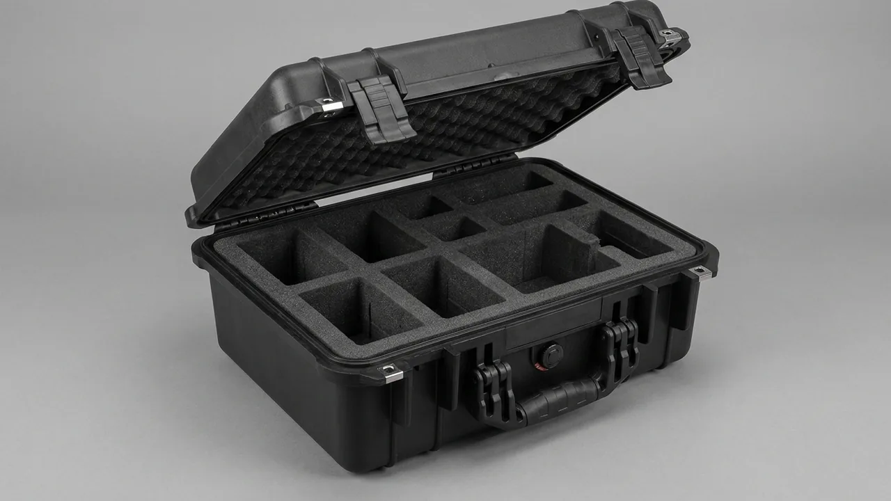
The first criterion for a filament winding case is not structural strength but whether the mandrel can go straight onto the machine on arrival, with its cylindricity, taper faces and surface condition intact. Product quality in filament winding depends heavily on the mandrel. Diameter uniformity comes from mandrel cylindricity and straightness, ease of extraction depends on the condition of the taper faces, and inner wall finish follows the mandrel surface. A local indentation, an ovalised section or a struck taper face can make extraction difficult enough to destroy the part, and in bad cases the mandrel itself is scrapped. The carriage, linear guides, delivery eye and tension unit are equally precision sensitive, while the resin bath, creel and electrical components fear moisture, dust and leakage. A winding equipment case therefore has to hold rotating-part accuracy and carriage-guide accuracy inside one packing system.
This article is written for equipment and process teams at winding plants producing pipes, pressure vessels, tanks and insulating tubes, for winding machine builders, spare parts distributors and engineering integrators. It covers mandrel support and anti-roll design, taper and extraction face protection, the carriage and linear guides, delivery eye and tension mechanism, spindle and chuck accuracy, the resin bath and fibre supply, servos and controls, case sealing and moisture control, and acceptance criteria, closing with a selection matrix, cost structure, FAQs and further reading.
Contents
- Machine layout and risk zoning by motion type
- Mandrels: cylindricity, taper and surface state
- Mandrel case support and anti-roll structures
- Mandrel lifting and extraction face protection
- The carriage and linear guides
- Delivery eye, guide head and tension mechanism
- Spindle, chuck and rotational accuracy
- Resin bath and fibre supply system
- Servo and control components
- Case structure, moisture and cleanliness
- Testing and acceptance
- Selection matrix and cost structure
- How customisation and delivery work
- Frequently Asked Questions
- Conclusion and related reading
Machine layout and risk zoning by motion type
A filament winder works on a simple principle: the mandrel rotates while a carriage traverses. The mandrel is held by the spindle and tailstock and turns about its axis, the carriage runs along the bed guideways, and the delivery eye travels with the carriage to lay impregnated tow onto the mandrel at the programmed angle. Components fall into four groups by motion type, with sharply different transit risks.
Rotation and clamping covers the mandrel, spindle, tailstock, chuck and steady rest. The mandrel is a rotating body with a large length-to-diameter ratio whose stiffness is governed by that ratio, so poor support produces bending or an oval section. The spindle taper and flange faces are location datums, and the chuck jaw faces are precision surfaces. Traverse and guidance covers the carriage frame, linear guides, bearing sliders, delivery eye and tension unit. Guide raceways are precision surfaces, sliders contain balls or rollers, and shock or contamination directly affects straightness and running resistance; the delivery eye bore is polished and any impact leaves a continuous rub on the tow. Impregnation and supply covers the resin bath, doctor roller, creel and guide parts, with risks of bath distortion, cured resin residue and chipped ceramic guides. Drive and control covers servo motors, gearboxes, encoders and control cabinets, with risks of corroded shaft extensions, shock-damaged encoders and damp electrical items.
| Group | Typical parts | Main failure mode | Packing strategy |
|---|---|---|---|
| --- | --- | --- | --- |
| Rotation and clamping | Mandrel, spindle, tailstock, chuck, steady rest | Bending, ovality, damaged fit faces | Half-round cradles with anti-roll stops, taper guards |
| Traverse and guidance | Carriage frame, linear guides, sliders, delivery eye | Damaged raceways, seized sliders, struck eye bore | Guard strips on guides, sliders restrained, eye in its own cell |
| Impregnation and supply | Resin bath, doctor roller, creel, ceramic guides | Distorted bath, cured resin, chipped ceramics | Temporary bracing, clean packing, one cell per item |
| Drive and control | Servo motors, gearboxes, encoders, cabinets | Corroded shafts, encoder drift, damp electronics | Shaft caps, individual cavities, dehumidified packing |
The table points to one organising rule: zone components by motion type. Rotating and guided parts must not share a cavity, because the mass of a rotating part pressing on a guide raceway leaves a permanent mark. Supply parts must not share space with electrical items, because resin and fibre dust contaminate control cavities. Zoning comes first, and only then do structural strength and sealing enter the design.
Mandrels: cylindricity, taper and surface state
The mandrel is the critical tooling in filament winding. Types include one-piece steel mandrels, aluminium mandrels, segmented mandrels, sand mandrels and plaster mandrels. Whichever type is used, three groups of features must survive transport.
Cylindricity and straightness. Diameter uniformity in the finished part comes directly from mandrel cylindricity, and long mandrels also need straightness. A mandrel is a rotating part with a very large length-to-diameter ratio, and mid-span deflection under uniform self-weight depends on a high power of support spacing, so end-only support produces visible sag and may leave residual deformation after long storage. On segmented mandrels, the assembled straightness matters as well as the straightness of each segment.
Taper and location faces. Most mandrels carry a taper or a locating shoulder at the end, used to locate against the spindle flange or the segment joint and to start the extraction. Taper faces are fits with tight tolerances, and impact damage raises a high point that prevents proper seating and can jam during extraction. Joint tapers on segmented mandrels are especially sensitive, because damage to one taper degrades the coaxiality of the whole assembly.
Surface state. Mandrel surfaces often carry a release coating, a chrome layer or a polished finish. Damage behaves differently here than in a pultrusion die: the inner wall of a wound part is a copy of the mandrel surface, so a local indentation normally produces a local raised or sunken area at the corresponding position rather than a defect running the full length. Even so, with many wound layers and complex interlaminar stress, such a local feature can become an initiation point for delamination or leakage. The target for surface protection is therefore no indentation, no scratch and an intact coating, not merely a clean appearance.
Moisture and corrosion. Exposed steel mandrel surfaces corrode readily during a humid sea voyage. Rust not only degrades the inner wall finish but also transfers onto the part during extraction. Aluminium mandrels oxidise and are prone to galvanic corrosion, particularly when in contact with carbon products or steel parts, so isolation is needed.
Mandrel case support and anti-roll structures
A mandrel case must hold, prevent rotation and allow extraction.
Cradle form. Half-round cradles are the standard solution for cylindrical mandrels. The arc should match the mandrel outside diameter, with a soft facing to spread contact stress. Matching the arc radius to the diameter matters: an oversized arc turns contact into two points, concentrating stress and marking a soft mandrel surface, while an undersized arc gives only local contact and concentrates the reaction in the cradle. On segmented mandrels, place cradles within a segment rather than at a joint, so that reaction forces do not act directly on a joint taper. For irregular mandrels with flanges or bosses, use a contoured board and put the supports under the large-diameter stiff regions.
Number and spacing of supports. Use at least three supports along the length, at both ends and mid-length, and four or more for very long mandrels. Take the permitted deflection as no more than half the straightness tolerance, with a dynamic factor of 1.5 to 2.0 applied. Resting a support on the end taper is one of the most common mistakes, because that position is both a datum and a relatively weak section, and load leaves a high point.
Anti-roll measures. Rolling is the most dangerous failure mode for a cylindrical part: once restraint is lost, the mandrel rolls inside the case and strikes the wall or other components. Three measures belong together. Give the cradle an arc greater than a half circle, or add a clamp, so the mandrel is restrained vertically. Add side blocks to limit horizontal movement. Add end stops to limit axial travel. Where the case base is flat, add a non-slip layer so that the whole case does not slide on the vehicle deck.
Extraction and loading. Because mandrels are heavy, the case should permit vertical lifting or rolling out along the cradles. If rolling out is chosen, use a low-friction cradle facing and fit a transition rail at the case mouth so the mandrel cannot drop off the edge.
Mandrel lifting and extraction face protection
Lifting and extraction face protection are the two most commonly underestimated parts of a mandrel packing scheme.
Lifting. Mandrels normally have lifting threads or lugs, so use matching eye bolts or dedicated gear. Slinging wire rope around the mandrel body is high risk: contact area is small, contact stress is high, and the mark is easily permanent. Where the sling crosses a taper or a fit face, the damage is immediate. Use fabric slings with a spreader beam so that contact falls inside the designated lifting zone, and keep sling angles within 60 degrees. For very long mandrels, use two lifting points with a spreader to prevent a bending moment developing along the length as the load comes on.
Extraction faces. The extraction faces are the tapers, shoulders and extraction ring areas. Fit guard sleeves or rings during transport, made from soft rather than hard material, and remove them before assembly. The guards must be clearly marked, so that nobody forces a joint closed with a guard still in place. Where an extraction mechanism is already fitted, treat its cylinder and push rods as slender actuators: cap the rod, plug the ports and avoid loading through the rod.
Choosing the shipping configuration. Some builders ship the mandrel pre-assembled to the spindle flange. In that case the supports should sit under the flange or a dedicated support pad rather than mid-barrel, so that the flange-to-barrel joint does not carry a bending moment. Whether to ship assembled depends on site lifting capacity, since a heavier single item changes both the number of support points and the lifting layout. Where extraction tooling is already mounted, confirm it cannot shift under its own weight in transit.
Surface corrosion protection. Apply a thin anti-corrosion film or tape to exposed steel surfaces and fit guards over the tapers. Choose products compatible with the release coating or plating, because additives can react with the coating or leave residue that interferes with extraction. On aluminium mandrels, avoid anti-corrosion products containing copper or chlorides.
The carriage and linear guides
The carriage is where machine accuracy is most concentrated and most easily lost in transit.
Protecting linear guides. The raceway is a ground precision surface, and sliders contain balls or rollers with cages. Three risks dominate. Contamination is the first: metal chips and glass fibre dust entering a slider accelerate wear. Impact loading is the second: a drop or collision indents the raceway through the balls, which then shows up as periodic noise and stick-slip in operation. Slider run-off is the third: a slider that runs off the end of its rail spills its balls. The countermeasures are to fix the slider near the middle of the rail with a stop limiting movement, fit guard strips or end caps, wrap the whole rail in anti-rust film and secure it.
Carriage frames and welded structures. Carriage frames are usually welded fabrications, at risk from distortion and detached accessories. Add temporary bracing across open directions to limit distortion, and either secure or remove protruding items such as delivery eye mounts and sensor brackets. Removed items must be itemised against the main assembly in the packing list, otherwise assembly stops for a missing fastener.
Shipping multi-axis carriages in parts. Where carriage, bed and guideways ship separately, record the fit state before dispatch, for example by marking slider positions, and restore to those marks on arrival. Where a machine ships as several units, matching case numbers to installation sequence saves significant site time.
Delivery eye, guide head and tension mechanism
The delivery eye and tension mechanism both work through functional faces, which makes them vulnerable in a specific way.
Delivery eye and bore. The tow bore is usually polished, sometimes with a ceramic insert to reduce wear. Once the bore edge is struck, passing tow is abraded, producing fuzz, and in serious cases single tows break. Give each eye its own cell, plug the bore with soft material, and never stack eyes against each other. Ceramic inserts follow brittle-part rules: no stacking, no compression load, limited acceleration.
Tension mechanism. Common types include magnetic particle brakes, servo-controlled tensioners and mechanical spring tensioners. The shaft and bearings of a magnetic particle brake are sensitive, so the shaft extension must not take impact. Sensors and encoders in a servo tensioner are shock sensitive and belong in individual precision packing. Tension rollers carry coated or polished faces and are treated as functional faces too.
Guide heads and tow path components. This group is numerous and small, and tends to be packed casually. Design the liner on a one-cell-per-item basis with soft padding and print item numbers onto the liner so the site can check against the drawing.
Spindle, chuck and rotational accuracy
The spindle and chuck set mandrel rotational accuracy, and once their fits are damaged the machine's runout specification cannot be met.
Spindle. The spindle taper or flange location face is the mandrel datum and must arrive free of impact damage and corrosion. Fit a protective plug in the taper, a cover plate on the flange face and a cap on the shaft extension. Where the spindle is already installed in the headstock, treat it as part of the machine assembly and make sure no other component's weight is carried through it. A spindle is stiff but precision critical, so lift only from the headstock or case lifting points, never from the spindle body.
Chucks and jaw faces. The jaw gripping faces of a three- or four-jaw chuck are precision surfaces and must be protected from impact and corrosion. The internal scroll mechanism can shift slightly under prolonged vibration, so close the jaws before packing and lock them. On hydraulic chucks, release hydraulic pressure and plug the ports.
Tailstock and steady rest. Tailstock centres and steady rest pads are fit surfaces: fit guards and secure them individually. A tailstock can travel along the bed, so lock it in position before dispatch so it cannot slide during transport.
For support and restraint practice on rotating components, see machine tool spindle component protection.
Resin bath and fibre supply system
Impregnation and supply components contact resin and fibre, so packing must cover distortion, contamination and leakage together.
Resin bath and doctor roller. Baths are usually thin-walled stainless weldments, prone to rim distortion and wall buckling. Fit temporary internal bracing, clearly documented as a transit item with a removal instruction, or use a strap-type cradle to limit rim distortion. Resin residue must be removed before dispatch: under transit temperature changes it flows, then gradually cures, and it is difficult to remove while also risking contamination of fresh resin at the next run. The doctor roller carries a functional surface, so sleeve it and secure it separately.
Creel and spindle shafts. Creel structures are welded frames with spindle shafts, at risk from frame distortion and shaft bending. Spindle shafts have high length-to-diameter ratios and need multi-point horizontal support with end caps, while open frame directions need temporary bracing.
Guides and ceramics. Ceramic guide eyes and tension rings follow brittle-part rules: one cell per item, soft bore plugs, limited stack height and no contact between ceramics.
Separate cases for resin and hardener. Where resin and hardener ship in the same consignment, give them their own cases and determine their regulatory status separately, so that a leak cannot reach the equipment. Some hardeners are corrosive or environmentally hazardous, and their packing and marking must be confirmed item by item against the transport regulations and the safety data sheet.
Servo and control components
The servo system covers spindle, carriage, delivery eye and tension loops, together with encoders, gearboxes and control cabinets.
Servo motors. Cap the shaft extension, and orient the cable entry upward or in a non-loading direction so that the seal is not under sustained load and cannot weep oil. Where a motor ships assembled to a gearbox, design the cavity for the group and carry load through the housing. The encoder inside a servo motor is shock sensitive, so drops and strong vibration must be avoided. For fixing and shock practice on motion control items, see packing notes for servo and motion controller components.
Encoders and sensors. Encoder shafts and code discs are fragile: cap the shaft, mount the body on its own, and leave a service loop in the cable. Tension and displacement sensors follow precision-item rules, with the load path kept away from the sensing face.
Control cabinets and drives. These fear moisture, dust and free-fall drops. Keep original packaging inside the outer case, or use a clean bag with desiccant. Glass fibre dust is not conductive, but once inside a cooling path it reduces heat rejection and contaminates terminals. Control internal relative humidity before closing the case.
Case structure, moisture and cleanliness
Structure follows component mass, form and re-use cycles; sealing and dehumidification follow voyage length and destination climate.
Structural forms. Mandrel cases are long and heavy, so use thick plywood cases, framed timber cases or steel-timber hybrids, with reinforced longitudinal beams in the base and a continuous load path between cradle and base panel. Carriage and guide cases can be framed timber or aluminium frame units. Delivery eyes, sensors and control items suit rotomoulded or aluminium frame cases with die-cut liners. Where a case is opened repeatedly, hardware life and replaceability become selection criteria; see choosing case hinges, latches and seals.
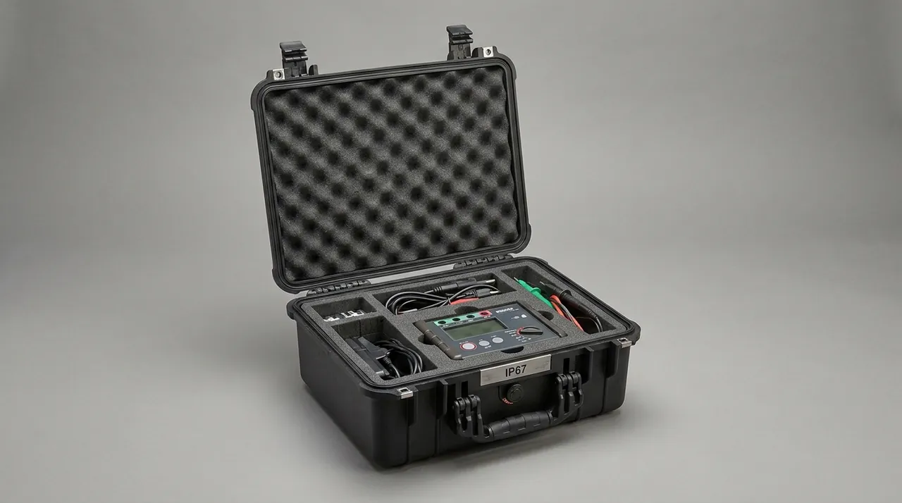
Sealing and breathing. Aim for at least IP65, and IP67 for long ocean voyages. Note that a fully airtight case creates a differential pressure problem: internal air expands and contracts with temperature, and without equalisation the case draws dust in when opened. Fit and verify a hydrophobic breather valve. Water protection is discussed further in achieving IP-rated water protection in cases.
Moisture and corrosion. Steel mandrels and steel parts corrode readily in a humid voyage, particularly where temperature cycling produces condensation. Apply an anti-corrosion film or tape to exposed metal, hold internal relative humidity at 45 to 55 percent, and size desiccant from net volume with at least 30 percent margin. For voyages over 30 days, use a replaceable desiccant cartridge with a humidity recording label. Avoid untreated timber as contact or filler material, because it keeps releasing moisture and is a common cause of uncontrolled internal humidity.
Cleanliness and dust. Glass fibre dust irritates skin and airways, so unpacking and cleaning should be done with protective equipment and filtered vacuum extraction rather than blowing. Where a liner is contaminated with fibre or resin and cannot be cleaned, replace the module. For mandrels destined for a controlled area, add a clean inner bag.

Testing and acceptance
Verification covers structure, dynamics, environment and cleanliness, with projects and criteria agreed in the technical protocol.
| Trial type | Trial carried out | Aim | Acceptance threshold |
|---|---|---|---|
| --- | --- | --- | --- |
| Structure | Stacking | Verify cradles and base hold shape under long static load | Sinkage within the agreed limit, cradles stay put |
| Structure | Lifting and forklift | Verify lug positions, fork pockets and beam strength | Nothing bent or cracked, fixings stay tight |
| Dynamic | Random vibration | Verify anti-roll and restraint survive prolonged shaking | Mandrel travel 2 mm or less, surface free of rub marks |
| Dynamic | Incline impact and drop | Verify end cushioning protects brittle parts | Peak acceleration inside the limit, raceways unmarked |
| Environment | Humidity and heat cycling | Verify corrosion and condensation are controlled | Metal faces rust free, no standing water |
| Environment | Water spray where required | Verify gaskets hold | Case interior dry |
| Cleanliness | Liner shedding and fibre check | Verify the liner does not release debris | Mandrel surface and eye bores visually clean |
Making criteria measurable. The core criteria for a mandrel are the measured change in cylindricity and straightness before and after transport, together with the visible condition of the taper faces and inspection records. For high-precision mandrels, mark measurement sections and datums before dispatch and re-measure the same positions on arrival. For carriage and guides, use no visible raceway indentation and no abnormal increase in slider resistance. For delivery eyes, use no impact high point in the bore and no chipping at the bore edge.
Test method sources. For vibration, shock, heat and humidity methods, MIL-STD-810H provides a usable source, with the caveat that it is quoted to select methods and does not amount to military certification or qualification. Consignments inside China use the GB/T 4857 series, while export orders use distribution cycle simulation.
Selection matrix and cost structure
What decides the scheme is component geometry, unit mass, haul distance and how often the case is reused. Typical combinations are set out below.
| Application | Part being shipped | Suggested case | Liner and support | Largest cost element |
|---|---|---|---|---|
| --- | --- | --- | --- | --- |
| New machine mandrel, domestic road | Long heavy rotating part, one-way | Thick plywood case with reinforced beams | Half-round cradles with anti-roll stops | Structural material and cradles |
| Imported mandrel replacement, ocean freight | Precision tapers, long voyage | Framed timber case with anti-rust film inside | Multi-point support, guards, desiccant | Protection process and dehumidification |
| Carriage and linear guides | Precision rails with sliders fitted | Framed timber or aluminium frame case with guard strips | Rail wrapping and slider restraint | Guide protection and fittings |
| Delivery eyes and sensors as returns | Small precision items, high frequency | Rotomoulded case with die-cut liner | One cell per item with soft padding | Liner process and dividers |
| Resin bath and creel | Thin-walled bath and welded frame | Timber case with temporary bracing | Strap cradle and rim restraint | Bracing and cradle |
Filament winding is driven by CNC payout, so fibre (glass or carbon yarn) and resin form the bulk of material cost while the mandrel is the main tooling; machine time for winding and cure outweighs direct labour. A representative split is fibre and resin 38 to 52 percent, mandrel and tooling 10 to 18 percent, liner and cradles 22 to 32 percent, cure and surface protection 8 to 14 percent, and hardware with marking 4 to 8 percent. Mandrel-case cost tracks mandrel length and mass: a longer, heavier mandrel needs more cradles and a larger case section, so separating long mandrels from spares at the design stage is usually cheaper than one oversized case and far easier to lift.
How customisation and delivery work
Five stages structure the project, each with a confirmable output.
- Technical input: parts list and drawings, mandrel length and mass, taper and location face positions, surface and coating specifications, guide size and slider state, transport mode and route, available handling equipment, and trip count.
- Design and calculation: cradle positions and support layout, deflection and load checks, liner materials with guard faces and dividers, corrosion protection plus moisture control, released as drawings with the calculation note.
- First article build: a pack, lift and roll-out or lift-out rehearsal using the real mandrel or an equivalent weight.
- Sign-off and first batch: fit and handling validated, then parameters and cleaning routine frozen.
- Volume build and shipment check: inspection per the agreed sampling plan, with packing list, cleaning register and inspection register issued.
Three steps deserve separate attention on winding machine projects. The first is cradle fit verification, because how closely the cradle arc matches the outside diameter determines indentation risk; run a seating check with the real mandrel at first article. The second is a guide condition record, documenting rail and slider state before packing so that existing marks are not attributed to transport. The third is a removed parts list, itemising everything detached from the carriage and mandrel together with its fasteners, so that site assembly is not delayed by a missing part.
On supply models, standard returnable cases come from stock, while mandrel cases and machine packing cases are built to drawing. For machine builders and engineering integrators, complete packing schemes can be matched to the installation schedule with supporting process documents. Winding machine case schemes and products are supplied by Kexin New Materials (Guangdong) Co., Ltd., with wholesale, agency, OEM/ODM production and global shipping all supported. Test and material documentation for winding components can be listed item by item in the contract.
Frequently Asked Questions
Q: What damage does a winding mandrel suffer most in transit? A: Surface indentation and high points on the taper faces, rather than obvious impact marks. Two mandrel features matter most: cylindricity, which sets diameter uniformity in the finished part, and end tapers, which govern extraction and the coaxiality of a segmented build. Indentation usually comes from inadequate support or hard material in the liner. When the cradle arc does not match the outside diameter, contact degenerates into two points, contact stress rises and a soft mandrel surface takes a permanent set. Taper high points come from impact, and once seated badly they cause poor contact and possible jamming at the start of extraction. Steel mandrels also rust in a humid sea voyage, and rust transfers onto the inner wall of the part during extraction. Three measures address all of this: cradles with arcs made to the actual diameter and faced with soft material, guards over the taper faces with no support ever placed there, and corrosion protection with low internal humidity.
Q: How should mandrel support be designed, and can a V-shaped cradle be used? A: A half-round cradle is the standard solution, provided the arc radius matches the mandrel diameter and the arc wraps far enough. If the arc radius is clearly larger than the diameter, contact becomes two points, stress concentrates and the surface takes marks. If the radius is clearly smaller, contact is local and the reaction concentrates in the cradle while stability suffers. Make the arc to the actual diameter, face it with soft material, and either extend the wrap beyond a half circle or add a clamp so the mandrel is restrained vertically. Use at least three supports, four or more for long mandrels, and place them on stiff regions rather than tapers or segment joints. Where the mandrel has flanges or bosses, use a contoured board and support the large-diameter stiff areas. Finally, do not forget anti-roll: cradle wrap, side blocks and end stops should all be present, because once restraint is lost a cylinder rolls and strikes whatever else is in the case.
Q: How do you pack carriage linear guides so they do not lose accuracy? A: Three things matter: contamination, impact and slider run-off. On contamination, metal chips or glass fibre dust entering a raceway or slider accelerates wear, so wrap the rail in anti-rust film, keep the case interior clean and confirm no particles remain before closing; where the rail is already mounted on the bed, cover the raceway with guard strips. On impact, balls pressed into a raceway leave indentations that appear later as periodic noise and stick-slip, so never load a rail in the same cavity as a heavy part and never let any component's weight rest on a guide. On run-off, a slider that travels off the rail end spills its balls, so centre the slider on the rail, fit a stop limiting its movement and add end caps. Recording slider positions before dispatch and restoring to those marks on arrival also shortens alignment time significantly on site, and it gives a reference point if the rail is later suspected of having moved during handling.
Q: Why do the delivery eye and tension mechanism fail so easily in transit? A: Because their working faces are small and extremely sensitive to surface condition. A delivery eye bore is polished and sometimes carries a ceramic insert; once the bore edge is struck, tow passing through is abraded, which at best produces fuzz on the part surface and at worst breaks single tows and disturbs tension uniformity. In a packed case the damage may be a faint mark that is easily missed at inspection. Tension mechanisms fail at the shaft and bearings. A magnetic particle brake shaft can develop runout after impact, and sensors or encoders in a servo tensioner can shift their zero point or produce signal faults, which show up as tension fluctuation whose cause is hard to identify. Effective practice is one cell per item with a soft bore plug and no stacking, brittle inserts treated as brittle parts with limited acceleration, and sensors packed individually with coiled, secured cables that are not repeatedly flexed.
Q: Can the resin bath and creel components be packed together? A: Not in the same cavity, although they can share a case if strictly zoned. The bath is a large thin-walled weldment at risk from rim distortion and wall buckling, needing temporary bracing or a strap cradle to limit movement. The creel is a welded frame with long spindle shafts, at risk from frame distortion and shaft bending, needing temporary bracing and multi-point support. Because the two need different support methods and cavity forms, mixing them makes each compromise the other, and any resin residue in the bath can leak onto the creel and guide parts. A better arrangement is zoning: bath in its own cavity, cleaned and braced; creel and spindle shafts in separate cavities with end caps. Where resin and hardener are also in the consignment, give them their own cases and determine their regulatory status separately, since some hardeners are corrosive or environmentally hazardous and require packing and marking confirmed against the transport regulations and the safety data sheet.
Q: What do glass fibre dust and humidity in a winding shop mean for packing? A: Both matter at three levels. For people, glass fibre dust irritates skin and airways, so unpacking, cleaning and liner changes should be done with gloves and a dust mask in a ventilated area. For the case interior, fibre debris entering a control cavity, a guide slider or a sensor cavity causes contamination; glass fibre is less conductive than carbon fibre, but mixed with grease it is much harder to remove, so zone electrical items away from fibre-generating parts with a dust barrier and clean with filtered vacuum extraction rather than compressed air. For metal parts, humidity is the more direct threat: steel mandrels and guide rails develop rust, which transfers onto the part inner wall or destroys guide accuracy. Hold internal relative humidity at 45 to 55 percent, fit desiccant and a hydrophobic breather, and avoid untreated timber as contact or filler material, since untreated wood keeps releasing moisture into a closed case and is a frequent cause of condensation on cold metal surfaces.
Q: How do you judge on arrival whether mandrel cylindricity has been affected? A: Use re-measurement under identical conditions with a difference-based criterion. Before dispatch, mark the measurement sections and datums while the mandrel sits on its transit supports, and record ambient temperature and support arrangement. On arrival, inspect the case, indicator labels and surface condition first, then remove restraints, place the mandrel on the same support arrangement and re-measure the same sections once the surface temperature is within the agreed band of ambient. Compare the two sets against the dispatch values. Take differences rather than absolutes, because support method, measurement datum and temperature all shift absolute readings and direct comparison invites error. If the difference under identical conditions exceeds the agreed limit, inspect the support positions for indentation, the taper faces for high points and the mandrel for evidence of having rolled. Keep dispatch, arrival and post-assembly records as a traceable chain, with temperatures attached to each, so that any later discussion about mandrel geometry can be settled from evidence rather than recollection.
Q: What should be watched with servo motors and control components on a winding machine? A: Their damage threshold is far below the heavy parts they travel with, and the damage is usually invisible. A servo motor's shaft extension is a weak point and needs a cap; the cable entry should face upward or in a non-loading direction so that sustained load cannot make the seal weep oil; where the motor ships assembled to a gearbox, load should be carried by the housing, not the shaft. The encoder inside the motor is shock sensitive, so drops and strong vibration must be avoided. Control cabinets and drives fear moisture, dust and free-fall drops, so keep original packaging inside the outer case or use a clean bag with desiccant, and control internal humidity before closing. The important reminder is that insulation and electronic performance damage is generally invisible at unpacking and only appears at power-up, so these items must be packed to a precision standard from the start rather than treated as ordinary structural parts.
Conclusion and related reading
A filament winding case has to protect two accuracy chains at the same time. The mandrel's cylindricity, straightness and taper faces set the geometry of the finished part and how easily it comes off the mandrel; the carriage guides, sliders and delivery eye set how reliably tow is laid down. A mark, a high point or a contamination event anywhere on either chain narrows the process window of the whole machine. The route to a reliable result is to zone by motion type, protect every functional face with a soft contact layer, and accept the shipment against measurable differences taken under identical conditions before and after transport. For buyers, handing over the mandrel drawing with taper positions, the guide specification with slider state, and the delivery eye and sensor lists in one package at design stage, then rehearsing seating and lifting at first article, is what keeps transit risk inside acceptable limits.
For support and restraint practice on rotating components, read machine tool spindle component protection. For cushioning and restraint structures, see matching cushion liners with restraint design. For lifting and fixing of long shaft-like parts, compare shaft component transport and lifting.
Related reading