

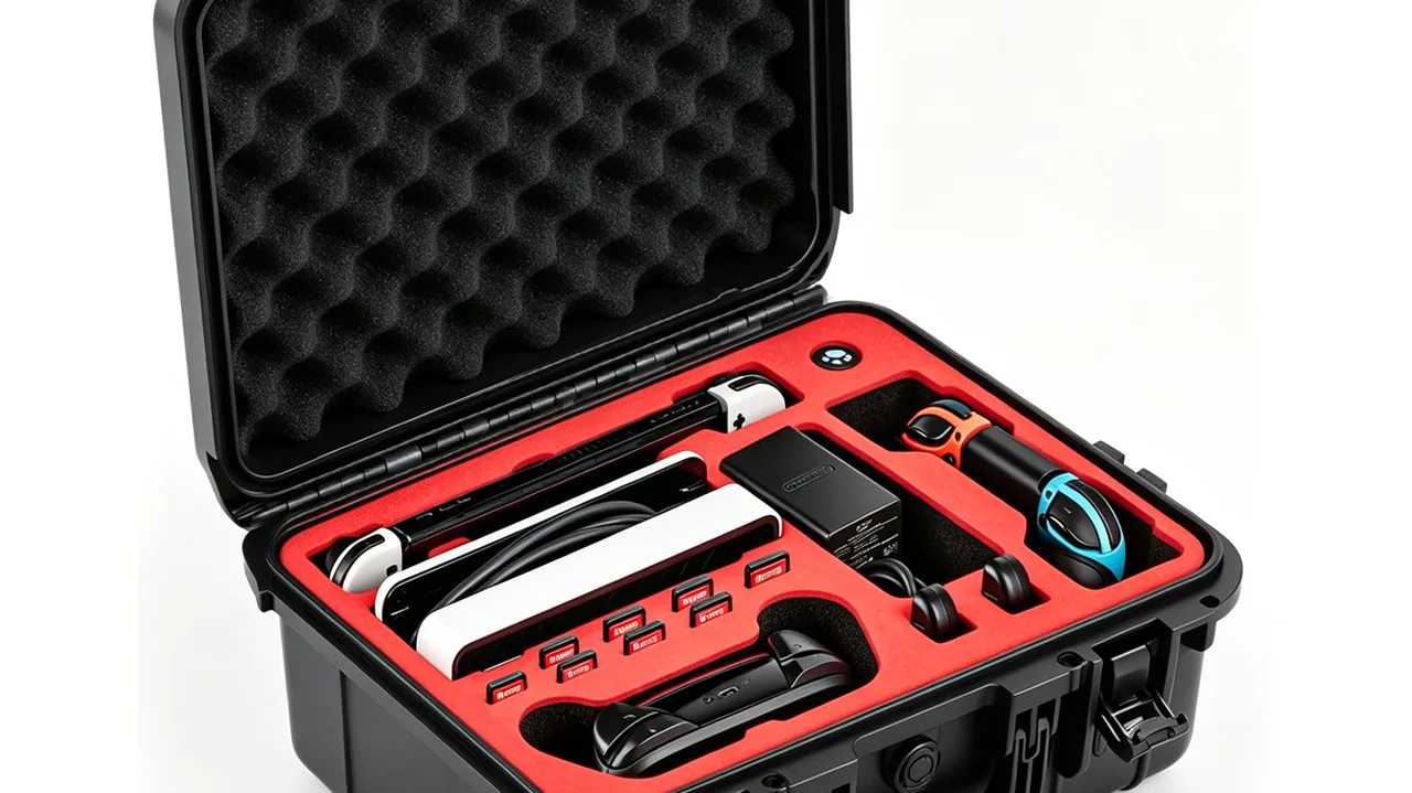
Touring, broadcast, exhibition and temporary event work share one logistical characteristic: the same equipment is dismantled, loaded, flown and reloaded by the same crew, and every loading event happens at the moment of greatest time pressure, in the small hours after a show while the venue is already counting down to lock-up. Equipment is pushed into cases, latched shut and rolled onto a truck, then extracted two days later in another city. Under that rhythm packaging receives no gentle treatment. It has to close correctly in one or two minutes, and it has to do so reliably after dozens of repetitions.
The principle JUNZHIJIA applies to flight case design is this: the first design objective for stage and broadcast cases is to make correct loading unavoidable rather than merely possible; protection performance is the second objective. A case that closes correctly only when the operator follows the right sequence will, in practice, be closed incorrectly, and the protection that was designed for will never actually be delivered.
Table of Contents
- What a Flight Case Is and How Touring Duty Differs
- Structure: Sandwich Panels, Extrusion Edges and Ball Corners
- Core Material Selection: Plywood, Honeycomb and Foam Composite
- Extrusions and Ball Corners: Load Path and Latch Mounting
- Compartment Design: Lighting, Audio, Control Surfaces and Cables
- Air Transport Constraints: Weight, Footprint and ATA 300 Reference
- Caster Systems: Layout, Braking and Centre of Gravity
- Sealing, Dust Control and Wet-Weather Loading
- Durability Under High-Cycle Touring Duty
- Liners and Fast-Setup Systems: Drawers, Rack Rails and Cable Channels
- How Flight Cases Differ from General and Rotomoulded Cases
- Acceptance Criteria and Common Failure Modes
- Frequently Asked Questions FAQ
- Conclusion and Related Reading
What a Flight Case Is and How Touring Duty Differs
A flight case is normally understood as a case built from sandwich panels, edged with aluminium extrusions and reinforced at the corners with ball corners. It originated in touring entertainment to carry lighting fixtures, loudspeakers, mixing consoles, video equipment and cable, and has since been adopted widely by broadcast, exhibition construction and event operations. The difference from a general protective case lies not in materials but in design assumptions. A general case assumes reasonably careful handling. A flight case assumes that it will be pushed, stacked, and closed by someone in a hurry.
Four operational requirements follow. The first is closing speed: the lid must close correctly even when the operator is interrupted, without relying on a sequence or a tool. The second is rolling capability: most cases need casters, and the centre of gravity relative to the wheelbase must permit rolling over ramps, thresholds and carpet. The third is stacking and nesting: warehouse and truck space is limited, so cases must stack in a regular pattern and ideally nest when empty. The fourth is identification: a single tour may involve dozens of cases, and they must be recognisable in a dimly lit backstage area, which makes colour and numbering systems essential.
As electronic content in touring rigs increases, cases also have to provide a baseline of electromagnetic and electrostatic isolation. For background on protecting electronic equipment in transit, see the guide to how outdoor cases protect electronic equipment.
| Usage pattern | Core requirement | Key structural feature | Avoid |
|---|---|---|---|
| --- | --- | --- | --- |
| Touring productions | Fast closing, rolling | Integral ball corners, braked casters | Latches needing tools |
| Broadcast and sport | Cable and console protection | Drawers, cable channels, rack frames | Deep undivided cavities |
| Exhibition build | Stacking and identification | Regular footprint, colour coding | Protruding hardware blocking stacks |
| Long-term storage | Stacking and dust control | High stacking face, gasket | Open unsealed seams |
Structure: Sandwich Panels, Extrusion Edges and Ball Corners
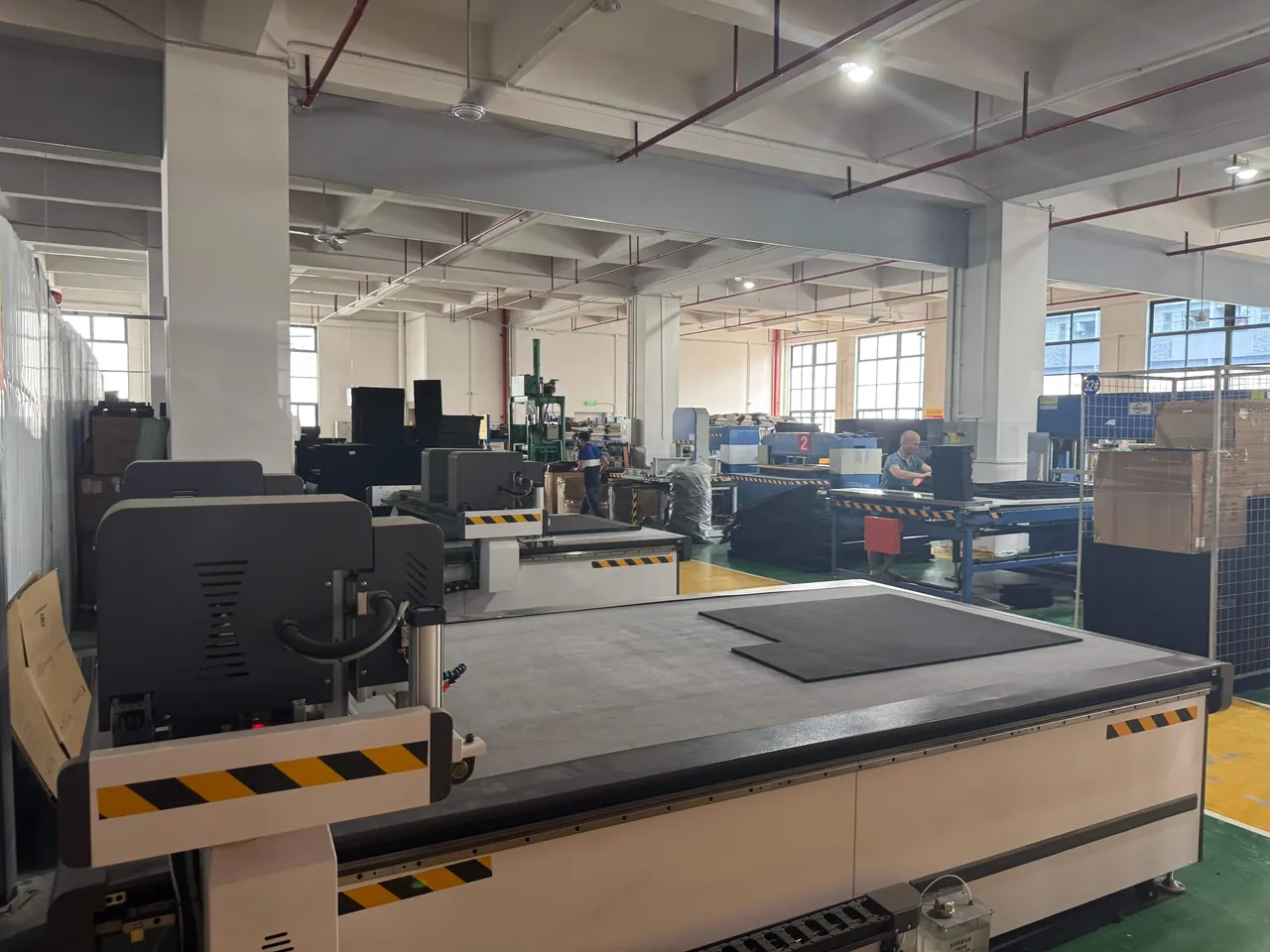
The classic flight case structure has three parts: a sandwich panel forming the surface, aluminium extrusion forming the edge, and ball corners reinforcing the vertices. Each has a defined role, and cutting corners in any one of them becomes visible quickly under touring intensity.
The panel carries out-of-plane loads and provides the sealing face. It consists of two skins with a core between them, usually 6 to 12 mm thick overall. The skins provide puncture resistance and appearance while the core provides stiffness and weight saving, the two joined by adhesive. Bond quality determines whether the panel delaminates under sustained vibration, and delamination is one of the most common early failures in flight cases.
The aluminium extrusion wraps the panel perimeter and does three jobs: it protects the panel edge against chipping, provides a mounting base for ball corners and latches, and forms the locating guide between lid and body. Extrusion sections typically include hollow chambers to reduce weight and screw channels so that panels can be seated and fastened directly.
Ball corners sit at the eight vertices and form the first structural layer against drop impact. They are usually die-cast aluminium or high-strength engineering polymer with internal ribs and a spherical outer transition to distribute stress. The connection between corner and extrusion must be reliable; the recurring failure is the fixing screw loosening under vibration, after which the corner falls away and the extrusion end is left exposed.
| Structural layer | Typical specification | Function | Common defect |
|---|---|---|---|
| --- | --- | --- | --- |
| Outer skin | 0.5–1.0 mm aluminium or laminated board | Puncture resistance, appearance | Scratches, laminate blistering |
| Core | Plywood, honeycomb paper, foam board | Stiffness and weight reduction | Poor bonding causes delamination |
| Inner skin | 0.3–0.8 mm aluminium or wear-resistant board | Liner mounting base | Moisture distortion |
| Edge extrusion | 6063-T5 extruded profile | Edge protection, load transfer, guidance | Distortion prevents smooth closing |
| Ball corner | Die-cast aluminium or glass-filled polymer | Absorb impact, distribute load | Fixing screws work loose |
Core Material Selection: Plywood, Honeycomb and Foam Composite
The core drives both weight and cost and is frequently the vaguest part of a specification.
Plywood core is the traditional option, usually 5 to 9 mm multi-ply. It offers good stiffness, strong screw retention, low cost and easy field repair, but it is heavy, sensitive to moisture and loses strength after prolonged exposure to damp conditions. For mainly road-based touring with limited weight sensitivity and a constrained budget, plywood remains the most economical choice.
Honeycomb paper core combines a paper honeycomb with two skins and can reduce weight by more than 40 percent against plywood of the same thickness, with good bending stiffness at equal thickness. Its weakness is low resistance to local impact and puncture: once a skin is pierced, the core takes in water, softens and loses load capacity quickly. Honeycomb therefore suits applications where weight is the binding constraint and the transport environment is reasonably controlled.
Foam composite core uses rigid foam such as PVC, PET or polyurethane, with densities typically between 60 and 200 kg/m³. It is light, thermally insulating, moisture resistant and can be moulded as a single piece, but it costs more, dents readily under impact and offers limited screw retention. For instrument cases requiring insulation or moisture resistance, foam core has clear advantages.
| Core | Typical thickness | Areal density | Bending stiffness | Impact | Moisture resistance | Cost |
|---|---|---|---|---|---|---|
| --- | --- | --- | --- | --- | --- | --- |
| Plywood | 5–9 mm | High | Excellent | Good | Poor | Low |
| Honeycomb paper | 10–20 mm | Low | Good | Moderate | Poor | Medium |
| PVC foam | 8–15 mm | Low | Moderate | Moderate | Excellent | High |
| PET foam | 8–15 mm | Low | Moderate | Good | Excellent | Medium-high |
| Aluminium honeycomb | 10–20 mm | Medium | Excellent | Good | Excellent | Very high |
A practical rule: choose plywood for road-dominated duty on a tight budget, choose honeycomb or foam where air freight dominates and weight is billed, and prefer foam core with a proper sealing design where the contents are moisture sensitive. Bond quality matters more than the core itself. Two cases of identical honeycomb specification can differ by a factor of three in service life if one has poor adhesive coverage.
Extrusions and Ball Corners: Load Path and Latch Mounting
The load path runs through the panel into the surrounding extrusion, along the extrusion into the ball corners, and through the corners into the supporting surface, with the corners deforming controllably during a drop to dissipate part of the energy.
Three points govern extrusion section selection. The first is wall thickness: edge extrusions are usually 1.2 to 2.0 mm. Too thin and the section crushes at the corner screw positions; too thick and weight rises without proportional benefit. The second is chamber geometry: a single-chamber section has lower stiffness, while a double or multi-chamber section bends less at equal wall thickness but is harder to extrude. The third is screw channel position: channels should sit near the mid-plane of the panel so that clamping force distributes evenly and the panel is not locally crushed.
Latch mounting directly affects closing reliability. Two families dominate: butterfly latches, which sit low and flat when closed and do not obstruct stacking but require some familiarity to operate, and draw latches, which are intuitive and simple but protrude beyond the case envelope. For high-cycle duty, specify draw latches with an anti-release feature and verify that a single engaged latch is enough to hold the lid closed, so that a rushed operator who misses one latch does not create an open gap.
Ball corner fixing deserves specific attention. The failure mode is screw loosening under vibration. Countermeasures include nylon-insert locking screws, elastic washers between corner and extrusion to compensate preload loss, at least three screws arranged in a triangle rather than in line, and thread-locking compound in the mounting holes. For heavily loaded corners, a through-bolt with a locking nut adds weight but improves reliability substantially.
| Extrusion and hardware | Key parameter | Criterion | Common problem |
|---|---|---|---|
| --- | --- | --- | --- |
| Edge extrusion wall | 1.2–2.0 mm | No crushing at corner screws | Local collapse if too thin |
| Profile chamber | Double chamber preferred | Better bending at equal wall | Insufficient stiffness when single |
| Corner screws | Three or more, self-locking | No loosening after vibration | Corner lost when screws release |
| Butterfly latch | Low profile when closed | Does not obstruct stacking | Missed latch if unfamiliar |
| Draw latch | Self-locking, anti-release | One latch holds lid | Protrudes and blocks stacking |
| Hinge | External, replaceable | Opening limited to 95–105 degrees | No limit tears hinge root |
Compartment Design: Lighting, Audio, Control Surfaces and Cables
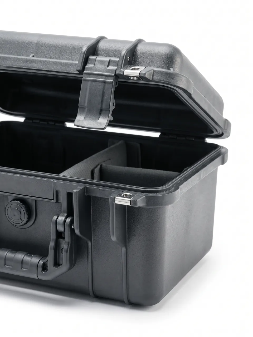
Internal partitioning is essentially the process of converting an equipment list into a case layout. The criterion for a good layout is simple: one person can load it on site without thinking, and once loaded it needs no further adjustment.
Lighting cases usually use two levels or front-and-rear cavities. Fixtures are numerous and similar in shape, and the usual problem is contact between units after loading. Individual pockets formed from EVA or EPE dividers solve this; pocket size should be the largest fixture envelope plus 3 to 5 mm, with space at the base of each pocket for cable so that cable is never trapped between fixture and case wall.
Audio cases prioritise vibration isolation and restraint. Loudspeaker magnet assemblies are sensitive to shock, so a single milled EVA liner holding each unit over a face contact area is preferable to a few point supports. For large enclosures the case may need an internal frame, since panel stiffness alone will not carry the load.
Consoles and mixing desks typically need a rolling case with a liftable rack frame and cable storage. The usual arrangement is a body plus a hinged lid that opens to serve as an operating surface, with cable and accessories contained in the lid. Fixing the console for transport while keeping it usable on site requires a removable clamp strip or quick-release strap rather than permanent fasteners.
Cable cases appear trivial but cause a disproportionate share of problems. Cable should be grouped by type and length using reconfigurable dividers. The design logic behind this approach is set out in the notes on removable divider systems.
| Equipment type | Recommended partitioning | Liner material | Key design point |
|---|---|---|---|
| --- | --- | --- | --- |
| Stage lighting fixtures | Individual pocket array | EPE dividers over EVA base | Leave cable space at pocket base |
| Loudspeakers | Single milled liner | EVA at 60–90 kg/m³ | Face contact, avoid point supports |
| Consoles and desks | Body plus hinged lid work surface | EVA with removable clamp | Balance transport fixing and access |
| Video and camera kit | Divided compartments with desiccant | EVA plus desiccant bay | Separate lens and body restraint |
| Cable and accessories | Removable divider grid | Rigid board with soft edging | Group and label by type and length |
Air Transport Constraints: Weight, Footprint and ATA 300 Reference
Air freight imposes three families of constraint: single-item weight limits, footprint constraints, and structural reference standards for the case itself.
On weight, most airlines set a handling limit for a single item of baggage or cargo, commonly in the region of 30 to 32 kg, above which special handling or palletisation is required. Design should therefore treat gross weight, meaning case plus contents, as a hard constraint tied to manual handling, or provide a dedicated means of moving overweight cases. Domestic road transport has no equivalent mandatory figure, but the same manual handling threshold affects loading efficiency and worker safety.
On footprint, the case envelope should align with pallet modules such as 1200 by 800 mm or 1200 by 1000 mm, or with simple divisions of them, so that loading wastes as little space as possible.
On structural reference, the ATA 300 series is commonly cited in the industry as a general reference for air transport containers, addressing load capacity, drop testing, stacking and mobility. It is important to be clear that this is an industry reference rather than mandatory regulation, and that acceptance should follow the project specification. Where the contents are electronic or communications equipment, electromagnetic compatibility and electrostatic protection requirements may also apply; the relevant considerations are covered in the structural notes on communications electronics protective cases.
| Constraint | Typical limit or requirement | Design response | Verification |
|---|---|---|---|
| --- | --- | --- | --- |
| Single-item weight | 30–32 kg manual handling reference | Control self-weight, split compartments | Weighing |
| Footprint module | Match pallet dimensions | Design to module | Dimensional check |
| Drop | Height per project specification | Energy-absorbing corners, internal cushioning | Drop test |
| Stacking | Layers per project specification | Reinforce stacking face and extrusions | Static stacking test |
| Rolling | Usable on flat ground and ramps | Caster specification and brakes | Rolling trial |
| Marking | Number, centre of gravity, orientation | Large-character labels | Visual check |
Caster Systems: Layout, Braking and Centre of Gravity
The caster system is the most underestimated part of a flight case. On site, cases spend most of their time being rolled, the state of the casters determines working efficiency, and a wrong specification produces long-term fatigue or even injury.
Caster diameter should match the floor. Diameters of 75 to 100 mm suit flat concrete and indoor flooring, while 100 to 150 mm crosses thresholds, carpet joints and cable ramps far more comfortably. On wheel material, hard nylon resists wear and rolls easily but transmits shock and noise; polyurethane is compliant, quiet and floor-friendly at slightly lower load capacity; rubber is quietest but has the highest rolling resistance.
Caster layout must account for the fact that uneven floors leave one wheel unloaded. The engineering response is to give one position a small amount of vertical compliance, or to use a larger wheelbase with a swivel group at one end so that stability is retained when only three wheels bear load. Cases longer than about 900 mm should have a fifth support at mid-length so that the body does not sag across the span.
Brakes are essential on ramps, in vehicle bodies and on stage decks. It matters how the brake engages: full-wheel brakes lock both rolling and swivelling and give the best holding, but release requires a deliberate action, whereas partial brakes lock rolling only and the case can still pivot in place. Where a case must be parked temporarily on a sloped tail lift, specify full-wheel brakes.
Centre of gravity is the most commonly neglected factor. A fully loaded case has a high centre of gravity, and rolling in a turn produces an overturning moment that will tip a narrow wheelbase. A practical rule is to keep the loaded centre of gravity no higher than half the wheelbase; where that cannot be achieved, load heavy items low, widen the wheelbase, or both.
| Parameter | Flat indoor floors | Thresholds and carpet | Ramps and tail lifts |
|---|---|---|---|
| --- | --- | --- | --- |
| Recommended diameter | 75–100 mm | 100–150 mm | 100–150 mm |
| Recommended material | Nylon or polyurethane | Polyurethane | Polyurethane or rubber |
| Brake type | Partial is adequate | Full-wheel brake | Full-wheel brake |
| Wheelbase | Centre of gravity at or below half | Same, widen if possible | Same, widening mandatory |
| Additional measures | None | Corner bumpers | Tow point and restraints |
Sealing, Dust Control and Wet-Weather Loading
Sealing requirements differ from those of an instrument case. A stage case is not expected to survive prolonged immersion, but it must keep contents clean through rain during loading, damp backstage areas and dusty stage environments. The design target is therefore sealing plus drainage, not the highest achievable ingress rating.
The primary seal is usually a soft strip between lid and body, or a sealing lip formed into the extrusion. For cases that do not target IP67, a single gasket combined with a drainage path is common, so that small amounts of water run off the outer wall rather than pooling on the mating face. Higher ratings require additional treatment of the extrusion joints, latch mounting holes and corner screw holes, which are the three main ingress paths in a flight case.
Dust control focuses on latches and hinges. Dust, fibre and theatrical haze enter latch mechanisms and make them stiff. Countermeasures include latches with dust covers, scheduled cleaning and lubrication, and avoiding groove geometry that traps debris. It is worth noting that sealing and shock resistance can conflict: an excessively hard gasket seals well but prevents the lid from seating under impact, so the shock is transmitted directly into the latches. The trade-off is discussed in the notes on coordinating seal and shock performance.
| Condition | Main risk | Sealing strategy | Maintenance focus |
|---|---|---|---|
| --- | --- | --- | --- |
| Loading in rain | Water pooling on mating face | Single gasket with drainage lip | Clear drainage channels |
| Dusty stage | Latch jamming | Dust-covered latches | Blow out and lubricate |
| Damp backstage | Internal moisture | Gasket plus desiccant | Replace desiccant |
| Coastal venue | Metal corrosion | Surface treatment and insulation | Check for galvanic corrosion |
| Cold outdoor site | Gasket hardening | Silicone gasket | Check compression recovery |
Durability Under High-Cycle Touring Duty
Touring cases work far harder than general protective cases: a single year may bring over a hundred loading, opening and stacking events. Durability design must therefore reinforce the specific components that see high cycle counts rather than simply increasing overall strength.
Latches see the highest cycle count and fail first. Design should address spring fatigue and pin wear, using geometry that leaves spring travel margin and pins with a wear-resistant coating, and the latch should be listed as a consumable in the spare parts schedule.
Hinges are similarly high-cycle. External hinges are easy to replace and are the rational choice for touring. The pin should be stainless steel running in a wear bush, with the opening angle limited to 95 to 105 degrees so the root is not levered.
Casters wear according to wheel material and floor abrasiveness. Nylon wears comparatively fast on grit-laden floors, so a quick-release caster socket that allows field replacement without tools is worth specifying.
Liners loosen over time under repeated clamping, particularly low-density foams. Specify EVA or high-density EPE and design the liner as a set of replaceable blocks so that worn regions can be renewed individually. Camera and video equipment combines precision mechanics with electronics, and its liner requirements are described in the notes on liner solutions for photography equipment cases.
| High-cycle component | Typical life | Reinforcement | Spares strategy |
|---|---|---|---|
| --- | --- | --- | --- |
| Latch | Thousands of cycles | Wear-resistant pin, spring margin | Listed as consumable |
| Hinge | Tens of thousands of cycles | Stainless pin with bush | Individually replaceable |
| Caster | Floor dependent | Quick-release socket | One spare set per case |
| Liner | Hundreds of loadings | EVA or high-density EPE | Block-level replacement |
| Gasket | Inspected every 20 loadings | Silicone material | Full-loop spare |
Liners and Fast-Setup Systems: Drawers, Rack Rails and Cable Channels
Fast-setup systems exist to compress assembly time from hours into minutes. Site time is extremely expensive in touring, and a well-designed setup system translates directly into shorter build and strike times.
Drawer systems suit tools, small accessories and spares. The design points are slide load capacity and retention: slides need adequate static capacity and a transport lock so that drawers cannot roll open when the case tilts. A push-to-release lock is preferable to a sliding catch because it is less easily knocked open.
Rack rails fix consoles and rack-mounted equipment. The usual approach is to install standard rack rails inside the case so equipment remains mounted during transport and can be connected immediately on arrival. This trades some cushioning performance for time efficiency, which means the case itself must provide more reliable vibration isolation.
Cable channels and routing give cable somewhere to go. Cable left loose in a case causes two problems: it has to be searched for on site, and it is repeatedly flexed in transit until conductors break internally. Provide channels sized to cable diameter with a retention feature at the opening so that cable cannot slide out during transport.
Note that setup systems add metal components, and therefore weight and cost. Define which systems are genuinely required rather than fitting drawers and rails to every case for the sake of completeness.
How Flight Cases Differ from General and Rotomoulded Cases
The differences follow from the operating assumptions. The table below is organised around the questions touring crews actually ask.
| Dimension | Flight case | General protective case | Rotomoulded case |
|---|---|---|---|
| --- | --- | --- | --- |
| Panel construction | Sandwich panel with extrusions | Single-piece moulded shell | Single-piece thick-wall shell |
| Self-weight | Medium | Medium to low | Medium to high |
| Sealing class | Typically dust and splash | Can reach IP65/IP67 | Can reach IP65/IP67 |
| Impact behaviour | Good, corners absorb energy | Good | Excellent |
| Repairability | Excellent, panels and hardware replaceable | Moderate | Poor, single-piece shell |
| Customisation freedom | Very high, arbitrary sizes and liners | Moderate, mould constrained | Low, tooling required |
| Minimum order quantity | Low, no large tooling | Low | High |
| Appearance and identification | Excellent, print and paint options | Moderate | Moderate |
| Typical use | Touring, broadcast, exhibitions | Instrument and tool transport | Outdoor and industrial storage |
Repairability is the standout advantage. A damaged panel can be replaced locally, a distorted extrusion replaced as a length, and a loosened corner re-fixed, so maintenance cost over a long service life is far below that of a one-piece shell. For a touring company running hundreds of loadings a year, that difference appears directly in total cost. Where contents are military or specialist electronics, additional hardening and shielding requirements apply, as covered in the notes on hardening requirements for military electronics cases.
Acceptance Criteria and Common Failure Modes
Acceptance should cover dimensions, assembly, rolling performance, sealing and durability. Because touring fleets are large and heavily used, criteria should be quantitative and suitable for sampling.
| Acceptance dimension | Example criterion | Verification method |
|---|---|---|
| --- | --- | --- |
| External dimensions | Nominal plus or minus 3 mm | Tape measure at three positions |
| Lid seating | Gap around perimeter 2 mm or less when closed | Feeler gauge |
| Latch | One-handed closing, no lost motion | Handling plus sampling |
| Corner fixing | No movement, screw torque within specification | Sampled torque wrench |
| Rolling | Acceptable resistance when loaded, no drift | Loaded roll over 10 m |
| Sealing | No significant ingress after 5 minutes of water spray | Sampled spray test |
| Stacking | No distortion after 24 hours at agreed load | Static stacking test |
| Liner fit | No movement with equipment loaded, gap 3 mm or less | Visual plus feeler gauge |
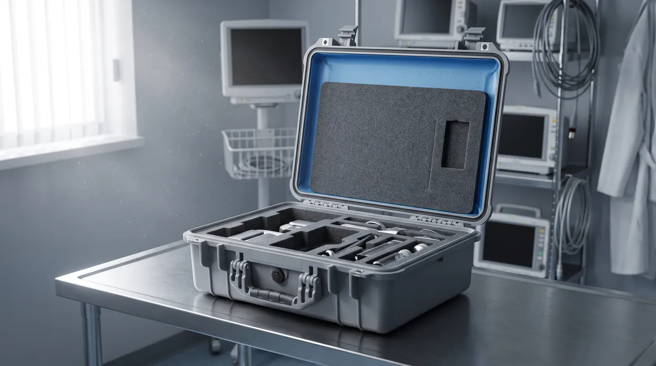
Field failures cluster at six locations, and each should have a confirmed countermeasure at the design stage.
| Failure mode | Trigger | Mechanism | Countermeasure |
|---|---|---|---|
| --- | --- | --- | --- |
| Corner falls off | Sustained vibration | Fixing screws loosen | Self-locking screws, elastic washers, thread lock |
| Panel delamination | Vibration and moisture | Adhesive bond fails | Improve bonding, seal the edges |
| Lid will not seat | Extrusion distortion or uneven floor | Locating lip binds | Add lead-in chamfer, control straightness |
| Latch failure | High cycle count | Spring fatigue, pin wear | Wear-resistant pin, list as spare |
| Caster failure | Abrasive grit on floors | Wheel wear, axle seizure | Quick-release sockets, cleaning |
| Mating face leakage | Loading in rain | Insufficient gasket compression | Thicker gasket, verify compression |
Frequently Asked Questions FAQ
Q: Can a flight case replace a general protective case?
A: Not entirely, because the design assumptions differ. A flight case assumes fast, rough handling and therefore prioritises closing speed and repairability, using sandwich panels, aluminium extrusions and ball corners so that panels, edges and latches can all be replaced individually. A general protective case assumes careful handling and pursues the highest protection for the lowest weight, using a single-piece moulded shell with generally stronger sealing. Where IP67 immersion protection is required, or where the environment contains heavy dust and chemical attack, a single-piece shell has a clear advantage, because a flight case has potential ingress paths at extrusion joints, latch holes and corner screw holes; reaching an equivalent rating requires extensive additional sealing and adds weight. Conversely, where cases must be opened frequently, rolled, customised to an equipment list, or repaired quickly, the flight case advantage is substantial. Most real projects combine the two: flight cases for high-cycle lighting and audio trolleys, moulded protective cases for precision instruments and water-sensitive equipment. Making that split explicitly at the specification stage is far cheaper than discovering after the first tour that half the fleet is either too heavy to fly or too slow to load.
Q: Should the core be plywood or honeycomb paper?
A: It depends on the weight constraint and the transport environment. Plywood core offers good stiffness, strong screw retention, low cost and easy field repair, but it is heavy and loses strength after prolonged moisture exposure, which suits mainly road-based touring with limited weight sensitivity and a tight budget. Honeycomb paper core can reduce weight by more than 40 percent at equal thickness and has good bending stiffness, which suits air-freight-dominated operations billed by weight and reasonably controlled handling; its weakness is low resistance to local impact and puncture, and once a skin is pierced the core absorbs water, softens and loses load capacity quickly, so it is not advisable where handling is rough or sharp impacts are possible. Foam composite core balances weight, moisture resistance and insulation, typically at 60 to 200 kg/m³, and suits moisture-sensitive instrument cases, though it costs more and dents readily under impact. With any core, bond quality matters more than the core itself: two cases of identical specification can differ by a factor of three in service life where one has poor adhesive coverage.
Q: What gross weight should a case and its contents be limited to?
A: Most airlines set a handling limit for a single item of baggage or cargo, commonly around 30 to 32 kg, above which special handling or palletisation is required, so this should be treated as a hard design constraint. In practice, establish the payload weight first and then set a self-weight budget for the case, with a common guideline that the case should not exceed about 40 percent of the payload weight, which preserves structural margin without making manual handling excessive. Where equipment must exceed the weight limit, plan one of two responses in advance. The first is to split the equipment across two cases, accepting the extra assembly time on site. The second is to provide a dedicated handling aid such as a stair-climbing trolley or a pallet, having first confirmed that the destination venue can accommodate it. Centre of gravity also matters: load heavy items low and close to the axle line so that the case does not tip during rolling. Domestic road transport has no equivalent mandatory weight figure, but the same manual handling threshold affects loading efficiency and worker safety and should be included in the design constraints.
Q: How should casters be selected for a flight case?
A: Three factors must be considered together: floor conditions, load capacity and centre of gravity. On floor conditions, casters of 75 to 100 mm suit flat concrete and indoor flooring, while 100 to 150 mm crosses thresholds, carpet joints and cable ramps far more comfortably, and touring duty should generally not go below 100 mm. On wheel material, hard nylon resists wear with low rolling resistance but transmits shock and noise; polyurethane is compliant, quiet and floor-friendly and is the general choice for touring; rubber is quietest but has the highest rolling resistance. On load capacity, confirm there is adequate margin per wheel in the fully loaded condition, and remember that a four-point layout leaves one wheel unloaded on an uneven floor, so either give one position slight vertical compliance or widen the wheelbase. Cases longer than about 900 mm should have a mid-length support to prevent sagging. Where a case must be parked temporarily on a sloped tail lift or stage deck, specify full-wheel brakes that lock both rolling and swivelling. Finally, control the centre of gravity, which should not exceed half the wheelbase when loaded.
Q: Why do ball corners come loose, and how is it prevented?
A: This is the classic flight case failure, and it originates in the loss of screw preload under sustained vibration. During road transport a touring case experiences continuous random vibration, and without anti-loosening measures the preload in a screw joint decays until, below a critical value, the screw begins to rotate slightly and loosens rapidly, after which the corner falls away and the extrusion end is left exposed as the starting point for later impact damage. Five countermeasures apply. First, use screws with nylon locking inserts so that friction resists vibration-induced rotation. Second, fit elastic washers between corner and extrusion so that elastic preload compensates for decay. Third, use at least three screws arranged in a triangle rather than in line, so no single point carries the load. Fourth, apply thread-locking compound in the mounting holes for additional vibration resistance. Fifth, for heavily loaded corners use through-bolts with locking nuts, accepting a small weight penalty for a substantial reliability gain. Torque checks should also be scheduled, typically quarterly or after each long tour, so that loosening is caught before a corner is lost.
Q: Can a flight case achieve IP67?
A: Technically yes, but the cost is significant and the value is usually poor. The structure creates several potential ingress paths: the bond line between panel and extrusion, the extrusion joints at the four corners, latch mounting holes, corner screw holes and the mounting points for handles and caster plates. Meeting an immersion rating requires treating each of these separately, for example double-sealing the corners with adhesive and gasket, using fasteners with sealing washers and specifying latches with sealed backing pads. These measures add material cost and assembly labour, increase weight by roughly 10 to 15 percent, and complicate field maintenance, because any operation that replaces a latch or a corner breaks the original sealing. In practice, therefore, flight cases are usually specified to a dust and splash standard combined with drainage geometry and desiccant. Where IP67 immersion protection is genuinely required, a moulded single-piece case is the better answer, or a two-layer approach can be used: an outer flight case providing mechanical protection and mobility, with a sealed inner container or vacuum bag providing water resistance.
Q: How often should touring case liners be replaced?
A: The trigger is whether the equipment has become loose, not how long the liner has been in service. The liner's job is to maintain a defined restraint between equipment and case, and once looseness appears the equipment gains extra travel during a drop or emergency stop, with measured acceleration rising by more than 30 percent, so replacement is due even if the liner looks undamaged. Inspection is straightforward: load the equipment, push against its edge by hand and look for visible displacement, or use a feeler gauge to measure the gap between equipment and liner, where anything above 3 mm requires action. Liner life depends on material, clamping frequency and payload weight. Low-density EPE loses thickness fastest under repeated compression and can loosen after a few dozen loadings, while EVA at 60 to 90 kg/m³ has very low compression set and supports much longer intervals. Liner design should therefore be modular, so that a worn region can be renewed without remaking the whole block. For touring companies running over a hundred loadings a year, an inspection after each long tour is advisable.
Q: How can touring cases be made easier to identify backstage?
A: Identification speed is a genuine cost variable in touring logistics. Because a single tour may involve dozens of similarly shaped cases, finding the right one quickly in a dimly lit backstage area shortens load-out considerably. Four measures are effective. The first is colour coding by function, for example a dark family for lighting, black for audio and a bright family for cable, since colour differences are easier to detect than text in low light. The second is large-character numbering applied to at least two adjacent faces, with a character height of no less than 40 mm so it can be read from several metres. The third is structured labelling, carrying not only the number but the tour name, a summary of contents and the gross weight, so handling staff can judge whether special treatment is required. The fourth is a consistent orientation marking, stating which face is up and where the centre of gravity lies, to prevent cases being loaded upside down. All markings should use wear-resistant materials; plain paper labels are destroyed within a few loadings, so laminated labels or direct printing should be used, with spare labels kept in the consumables stock.
Conclusion and Related Reading
Flight case design treats time pressure as a load case with the same standing as impact and moisture.
Related Reading