

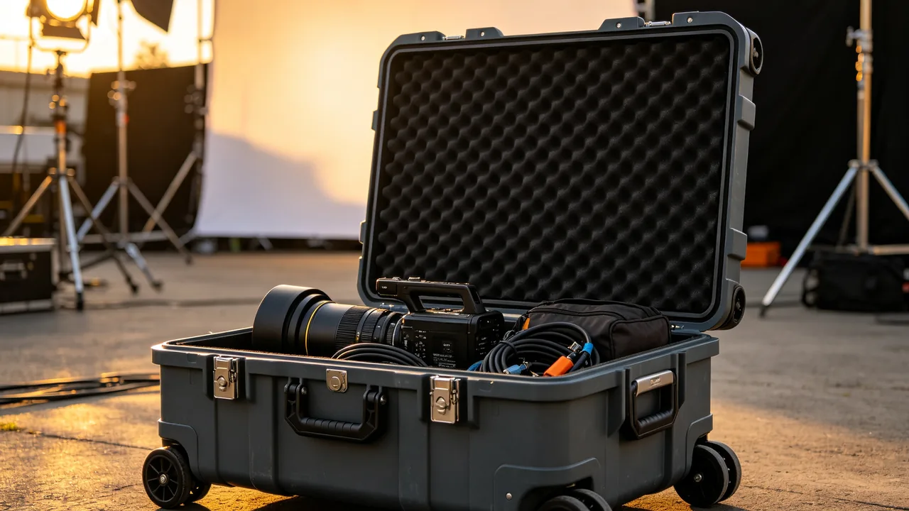
An OEM plastic box project is not complete when a logo is applied to a stock enclosure. The customer needs equipment geometry, protection targets, brand identity, compliance inputs, and supply requirements converted into a product that can be molded, inspected, replenished, and traced. The manufacturer must coordinate resin, structure, tooling, color, latches, sealing, inserts, labels, packaging, and documents. Without revision control across these elements, an attractive sample can become a production box that fits poorly, changes color, or develops inconsistent closure force.
JUNZHIJIA defines OEM plastic-box delivery as a controlled manufacturing program that connects the requirement baseline, shell and mold, brand elements, inserts and accessories, verification evidence, and batch traceability rather than a one-time private-label operation. This guide explains platform selection, new-tool development, material and wall design, DFM, mold approval, color and graphics, foam integration, process quality, and OEM or ODM document handover.
Table of Contents
- Freeze OEM scope and the product requirement baseline
- Choose a platform box or a purpose-built mold
- Specify plastic materials, colors, and compliance inputs
- Coordinate shell engineering with manufacturability
- Manage mold engineering, trials, and service life
- Engineer color, texture, logos, and brand processes
- Integrate inserts, accessories, and payload interfaces
- Structure samples and the verification matrix
- Control molding, assembly, and production quality
- Maintain sealing, environment, and transport performance
- Deliver packaging, traceability, and brand documents
- Manage quotations, changes, and long-term supply
- Frequently Asked Questions FAQ
- Conclusion and Related Reading
Freeze OEM Scope and the Product Requirement Baseline
The first step is to distinguish OEM from ODM responsibility. In a typical OEM program, the customer provides a brand and a substantially defined product or performance target, while the manufacturer engineers it for production. In an ODM program, the supplier may additionally perform requirement analysis, architecture, platform selection, and verification planning. Either model needs an approved baseline covering payload CAD, maximum mass, center of gravity, fragile areas, exterior envelope, opening direction, access frequency, ingress target, temperature, chemicals, transport, color, graphics, packing, forecast quantity, and intended life.
Requirements should be divided into mandatory, preferred, and unresolved items. An outside dimension driven by an aircraft or rack interface may be mandatory. A request for convenient one-hand carrying may conflict with payload mass. A statement such as military grade remains unresolved until a condition and acceptance criterion are defined. Protection language should become measurable: rated payload, drop height and orientations, stack load and duration, named ingress method, and payload functional checks. Without these details, waterproof, rugged, or heavy duty can mean different things to purchasing, engineering, and production.
Input files need revision identity and ownership. Payload CAD should identify reference planes, connector movement, approved support zones, and configuration options rather than providing only a rendering. Brand files should include vector artwork, color standards, clear-space rules, and prohibited treatments. Restricted-substance or market documentation needs a defined destination and scope. The manufacturer can then return a concept, risk register, assumptions, and verification plan. How to choose a case OEM factory offers useful supplier-screening criteria, but evidence, process capability, and change discipline should govern the final decision.
| Requirement area | Essential input | Frozen output |
|---|---|---|
| --- | --- | --- |
| Payload and accessories | CAD, mass, center of gravity, fragile zones | Usable cavity, supports, and relief boundaries |
| Protection | Drop, vibration, stacking, ingress, environment | Methods, conditions, specimen count, acceptance |
| Brand identity | Vector logo, color standard, label content | Process drawing, location, and master sample |
| Commercial plan | Quantity, releases, timing, target economics | Platform or tooling route and capacity assumptions |
| Documents | Labels, serials, reports, and languages | Deliverable list and approval ownership |
A baseline does not prevent improvement; it makes change visible. Every open assumption should have an owner and due date. When equipment, forecast, or compliance inputs change, the project can identify affected structure, tool, insert, validation, cost, and schedule rather than silently building to an obsolete conversation.
Choose a Platform Box or a Purpose-Built Mold
A platform box is appropriate when an existing usable cavity closely matches the equipment, launch pressure is high, forecast volume cannot justify a dedicated tool, or differentiation concentrates in color, insert, graphics, and accessories. The advantage is established shell geometry, available manufacturing history, and lower one-time investment. The limitation is a fixed outside envelope, closure layout, handle position, draft, and internal rib geometry. The insert cannot be made dangerously thin simply to force a mismatched payload into the nearest catalog size.
A purpose-built mold is appropriate when the payload envelope is unusual, the program has stable volume, brand form is important, or the case needs dedicated ports, stacking, mobility, locks, or load paths. New tooling can optimize structure, access, and material use, but it requires engineering, flow analysis, tool manufacture, trials, correction, and qualification. The investment decision should compare unit resin and assembly, tooling, expected tool life, verification, modification risk, and product lifetime instead of focusing only on the first purchase order.
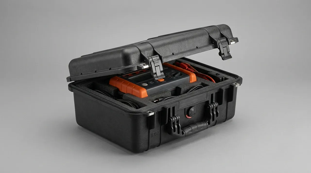
A gap matrix makes the decision explicit. Compare the platform with required exterior, usable cavity, payload mass, sealing, color, logo zone, accessory attachment, and available test evidence. Classify each item as compliant, secondary-operation capable, tool modification required, or infeasible. Drilling a port alters shell strength and ingress performance. Substituting a valve or latch changes preload or flow. If a platform has a fundamental performance gap, a new tool or revised requirement is safer than hiding the mismatch under foam.
The routes can be combined. A dedicated shell may use previously qualified latches, handles, valves, and gasket sections, reducing component risk. A platform shell may receive a modular tray that supports several equipment variants. Reused parts still need controlled model and supplier identities. Two parts with similar appearance can differ in resin, spring force, corrosion resistance, or endurance.
Product maturity also affects timing. If the enclosed device is still changing weekly, a machined engineering enclosure or adaptable liner can freeze access and support before steel is cut. Once tooling starts, even a small connector or battery change can alter ribs, mold slides, cooling, and validation. A formal design-freeze gate protects both parties from avoidable rework.
Specify Plastic Materials, Colors, and Compliance Inputs
Material selection should combine service temperature, impact, stiffness, creep, ultraviolet exposure, chemicals, flammability, appearance, mass, and molding method. Modified polypropylene commonly balances toughness, weight, and economics. ABS can provide dimensional and surface benefits. Polycarbonate and blends offer other stiffness-impact combinations. Polyethylene suits some large or rotationally molded structures. A generic polymer name is insufficient for OEM control. The specification should identify approved grade, additives, color concentrate, allowable regrind, and performance characteristics.
Color is not purely decorative. Pigments can influence shrinkage, flow, weathering, and cold impact. Dark and light shells also develop different solar surface temperatures. A brand color should begin with an objective standard, then be represented by a molded plaque or case using production-intended resin, texture, and thickness. Approval should define illumination, viewing geometry, instrumental difference, gloss, and texture. An RGB value viewed on a screen cannot serve as the sole plastic acceptance standard.
Compliance inputs depend on sales region and end use. They may include restricted substances, material declarations, recycling marks, flammability, or specialized contact requirements. A claim should never be broadened beyond its tested or documented scope. If the complete case contains metal hardware, electronic trackers, adhesives, ink, labels, or foam, the requested compliance package must clarify whether those materials are included. Report validity, sample representation, and supplier declarations should be agreed early.
The overview of protective case plastic materials supports initial comparison, but finished molded parts still need relevant cold-drop, hot-stack, chemical-wipe, or ultraviolet verification. Standard coupons do not reproduce weld lines, residual stress, texture, thickness changes, pigment effects, and assembly load.
Supply control should address more than a grade name. Base-resin source, compound formulation, concentrate supplier, blending ratio, drying when applicable, and traceability affect consistency. An apparently equivalent resin is an engineering change. Retained material samples, certificates, melt-flow or density checks, and periodic performance tests can be selected according to risk.
Coordinate Shell Engineering with Manufacturability
OEM shell design balances protection, weight, molding, and brand area. Nominal wall thickness follows resin behavior, projected area, flow length, and process stability. Local stiffness comes from ribs, returns, closed perimeter sections, radii, and carefully placed double-wall zones. Ribs should carry lid, base, and payload reactions toward the frame, feet, handles, latches, and hinges rather than decorate an otherwise unsupported panel. Abrupt thickness changes, sharp corners, isolated bosses, and deep molded lettering can cause sink, weld lines, air traps, or stress concentration.
A design-for-manufacture review should address pull direction, draft, parting lines, undercuts, slides, gates, ejection, ventilation, cooling, texture, and critical dimensions. Cosmetic and structural needs often conflict. A recessed logo can thin a primary surface. Deep texture needs more draft. A thick latch rib may create sink on the brand face. The answer is a coordinated section redesign before tool release, not an attempt to hide structural geometry later with process adjustment.
Seal geometry receives special priority. The gasket groove, compression land, frame flatness, latch locations, and lid-to-base shrinkage must create repeatable perimeter pressure. A label pocket, divider mount, or cable port cannot intrude on that path without review. Molded stack features need adequate contact area, manufacturing clearance, and drainage. Handles require gloved clearance, acceptable pinch zones, and a load path that avoids peeling a thin wall.
Structural and mold-flow analyses answer different questions. Structural work compares deflection, strain, load transfer, and connector forces. Mold-flow work examines filling pressure, weld-line location, air traps, packing, shrinkage, and warpage. Both rely on assumptions and must be correlated with trial-part wall measurements, dimensions, and physical loading. A passing simulation does not qualify the product, while one good hand-selected sample does not establish a production window.
Human factors need prototype evidence. Check payload loading, finger access, latch force, opening angle, label visibility, stacking separation, and whether a connector can be used without removing the device incorrectly. For cases with wheels, pull handles, panels, or metal frames, account for mixed-material expansion, fastening, abrasion, and service replacement.
Manage Mold Engineering, Trials, and Service Life
The mold agreement should define cavity count, base and insert steels, surface texture, hot or cold runner, expected service life, maintenance, wear components, acceptance, storage, and ownership. Large lids and bases are sensitive to flatness and coordinated shrinkage, so cooling circuits, flow balance, packing, and ejection directly affect closure. A tool-life statement should specify normal resin and processing assumptions, maintenance intervals, and exclusions rather than presenting one unsupported cycle number.
Trials usually proceed in stages. An early trial reveals filling, ejection, sink, air traps, initial warpage, and gross dimensions. Later trials stabilize process, implement controlled steel corrections, approve texture, and approach production conditions. Every run should retain machine parameters, resin lot, sample identity, measurement timing, and a structured issue list. Samples made under different conditions should not be mixed to create a favorable conclusion.
Key dimensions include perimeter flatness, lid and base diagonals, groove section, latch and hinge centers, stack registration, interference zones, and liner reference surfaces. Appearance criteria should classify sink, flow lines, weld visibility, color, texture injury, flash, and ejection marks. Measurement occurs after a defined conditioning period because a large polymer part may continue shrinking or changing shape after ejection.
Assembly fit is not the end of tool qualification. Trial parts need closure cycles, handle load, stack load, drop, and ingress checks according to the matrix. A cosmetic steel change can affect section thickness or shrinkage. A correction near the gate can move a weld line. Regression should therefore follow the function touched by each correction.
Development timing principles in custom protective case prototyping help organize gates, but approval quality determines readiness. Mold history should continue during production, recording preventive maintenance, polishing, welding, insert replacement, gate changes, and incidents. Repair of a seal land, main rib, gate, or critical cavity feature should trigger dimensional review and applicable partial requalification.
Engineer Color, Texture, Logos, and Brand Processes
Brand identity can use molded color, tool texture, raised or recessed logos, screen printing, pad printing, heat transfer, laser marking, adhesive graphics, data plates, or combinations. Selection depends on volume, number of colors, detail, wear, ultraviolet exposure, cleaners, curvature, and expected revisions. A molded logo is durable but changes through steel work and may alter wall geometry. Printing is flexible but needs surface preparation and adhesion evidence, especially on low-surface-energy polymers. A plate adds a durable premium appearance but introduces fastening, adhesive, corrosion, and possible sealing interfaces.
The logo drawing should include vector geometry, dimensions, datum-based position, direction, minimum line width, colors, process, and tolerance. Approval by screenshot is inadequate. Curved surfaces distort perception, stacking contact can abrade artwork, and an open latch can cover required text. Placement should avoid seal lands, high-strain hinge areas, critical ribs, repeated rubbing, and mold features that force visible defects.
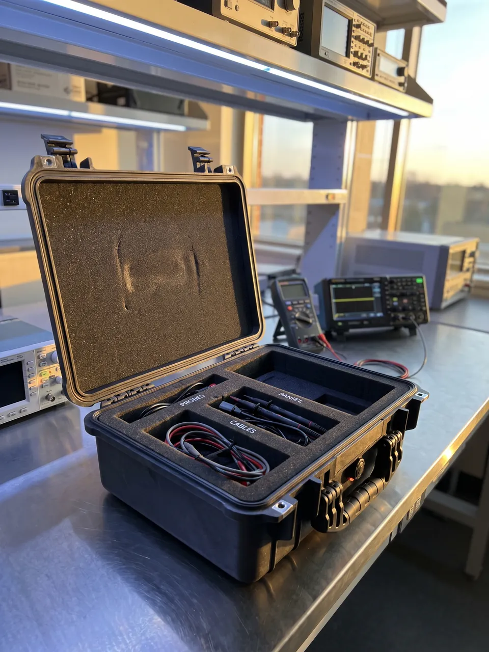
A molded master establishes color and texture. Instrumental values and sample validity support it. Lid and base should be approved together when separate tools, thickness, or flow orientation create a visual difference. Printed graphics need criteria for location, registration, pinholes, edges, opacity, and adhesion. Rub, tape, cleaner, and ultraviolet exposures should represent actual use, with acceptance checked after conditioning rather than immediately after printing.
Branding includes serial numbers, machine-readable codes, warnings, model names, and regulatory marks. Fixed and variable information need separate data ownership. Code rules should prevent duplicates, and scanning must be verified on the real texture, radius, contrast, and lighting. If the customer transmits serialized data, receipt, reconciliation, rejected-label destruction, and reprint control become production processes. Protective case color customization provides a useful color-approval reference.
Brand assets require authorization and version control. The manufacturer should use approved marks only for the agreed product and quantity. Obsolete labels, rejected marked shells, and old document packs need contractual disposition. When artwork changes, both parties must decide whether previous inventory can ship, be reworked, or be scrapped so two versions do not enter the market unintentionally.
Integrate Inserts, Accessories, and Payload Interfaces
The insert converts a general shell into a payload-specific product. Inputs include payload CAD, mass distribution, fragility, handling, accessories, and allowable acceleration. EPE, EVA, PE, and cross-linked variants differ in support, recovery, machining, and appearance. Color or nominal density alone cannot determine suitability. Working stress should use payload bearing area and available thickness, with relief around displays, controls, antennas, optics, and connectors.
Cavity tolerance includes device variation, foam cutting, layer bonding, assembly, and temperature. Excessively tight fit makes removal difficult and can continuously load delicate areas. Loose fit permits movement under vibration and impact. Finger pulls, extraction straps, and accessory cavities must not cut through the narrowest load-bearing section. Lid foam should prevent bounce, not compensate for an inadequately located base by forcing the payload downward.
Detailed insert development can follow custom EVA foam insert processes. Production-representative equipment should be trial-fitted for loading, extraction, connector access, lid closure, and accessory storage. When the device is not final, a mass-and-center-of-gravity simulator may support early impact work, but final production geometry still needs confirmation. Cutting files, material grade, adhesive, layer sequence, reference datums, and inspection templates require revision control.
Accessories may include locks, shoulder straps, backpack systems, casters, pull handles, panel frames, valves, document pockets, or electronic tags. Every accessory affects load, sealing, balance, or operation. Strap points need rated-load dynamic verification. A panel cutout needs renewed frame and ingress review. A document pocket must not mask a gasket. Platform accessories still require controlled model and source because visual equivalents may have different resin, spring force, or fatigue life.
Assembly should remain serviceable. A replaceable gasket or valve needs access and torque instructions. Adhesive-backed foam must use compatible surface preparation. Fasteners should not create sharp points inside the liner. If an accessory is optional, the order code and work instructions must prevent a configuration with an open hole, missing seal, or incompatible document pack.
Structure Samples and the Verification Matrix
Appearance, engineering, tool, and approval samples have different purposes. An appearance sample establishes color, texture, logo, and general layout but may not demonstrate structural performance. An engineering sample checks volume, access, human factors, and insert arrangement. A tool sample confirms actual material, molded dimensions, assembly, and defects. The approval sample is made under frozen, production-representative conditions and passes the agreed verification plan. Every sample needs an identity, revision, material, process state, and intended use.
The verification matrix connects each requirement to a method, condition, specimen count, measurement, and acceptance rule. Typical items include dimensions, latch and hinge cycles, handle loading, stacking, vibration, face-edge-corner drops, thermal cycling, dust or water ingress, chemical wiping, marking abrasion, and payload function. If an ISTA, ASTM D4169, IEC 60529, or national method is referenced, the specific procedure and parameters should be written rather than citing only the standard family.
| Verification | Specimen state | Principal acceptance evidence |
|---|---|---|
| --- | --- | --- |
| Fit and dimensions | Conditioned case with rated payload | No interference; access and closure within limits |
| Drop and vibration | Rated mass and defined orientations | No penetration; payload position and function pass |
| Stacking | Loaded, specified time and temperature | Residual set and seal function remain acceptable |
| Ingress | Agreed valve and interface configuration | Dust or water result meets the named method |
| Marking durability | Production surface and pretreatment | Adhesion, readability, and scan rate meet limits |
| Closure cycling | Production latch, hinge, and gasket | No fracture; force and compression remain stable |
Failures need a closed issue record containing observation, specimen, stage, cause, correction, responsibility, completion evidence, and regression scope. An insert change may alter latch load. A thicker wall changes shrinkage and cavity. A new color concentrate may alter impact. The return test should follow affected interfaces instead of repeating only the test that visibly failed.
Approved masters and raw reports should be retained by both parties when appropriate. Photographs alone cannot define color, force, dimension, or internal damage. Calibration identities, filtering, conditioning, payload configuration, and deviations make results reproducible. A signed sample without a matching revision record is an unreliable production standard.
Control Molding, Assembly, and Production Quality
Production control translates final performance into observable process characteristics. Molding records can include resin lot, concentrate ratio, regrind, drying, melt and mold temperatures, pressure, cooling, and cycle. Dimensional control focuses on frame, groove, latch and hinge locations, cavity, and stack features. Assembly control covers fastener torque, gasket joint, valve installation, latch force, insert position, and label identity. Finished-product appearance inspection alone cannot detect all these sources of drift.
First-article approval should use consecutive parts from a stable process rather than specially adjusted singles. It confirms dimensions, appearance, assembly, material, and required functional evidence. Control charts can track critical dimensions. Limit samples support appearance and color. Instruments should measure closure force rather than relying on operator feel. Fixtures and scans can prevent left-right hardware reversal, twisted gaskets, incorrect foam layers, and wrong label orientation.
Sampling concepts in custom protective case AQL acceptance can separate critical, major, and minor defects. A load-path crack, missing seal, wrong resin, or unsecured payload is not an ordinary cosmetic defect. Destructive tests cannot be applied to every box; first-article, lot, periodic type, and change-triggered tests provide a layered control plan. Sampling does not replace control of the process that creates the characteristic.
Incoming quality covers latches, valves, fasteners, foam, inks, labels, and packaging. A purchase description should include relevant dimensions and performance, not merely a house part number. Supplier or manufacturing-location changes need review. Lot identity, retained samples, and records allow a field issue to be linked to resin, cavity, machine, shift, assembly batch, and inspection.
Rework deserves a controlled method. Adhesive replacement, drilling, heat staking, print removal, and seal repair can introduce contamination or hidden weakness. Operators need authorized instructions and a new inspection point. Product outside the approved route should enter review rather than being made visually acceptable and returned silently to the lot.
Maintain Sealing, Environment, and Transport Performance
Dust and water resistance result from the shell, frame, gasket, latch, valve, and every interface. Gasket cross-section, squeeze, groove fill, joint, and compression set require control. Frame warpage can unload a segment, while excessive latch preload accelerates gasket set. If a branded product adds riveted plates, panels, electronics, or cable ports, the final assembly may need new assessment rather than inheriting the untouched shell result.
An IP65 or IP67 claim should identify the method, load state, valve configuration, spray or immersion parameters, duration, and judgment. IP67 immersion testing provides useful method context. The result does not promise unlimited depth, time, dynamic pressure, elevated water temperature, or chemical liquid. Drop, thermal cycling, and closure aging can change frame alignment and gasket recovery, so test order should reflect relevant service interaction.
Environmental exposure may include hot and cold conditions, humidity, ultraviolet light, salt, and chemicals, selected from actual use rather than a generic checklist. Salt exposure often targets metal hardware and connections; it does not automatically predict every coastal lifetime. Chemical wiping should use customer cleaners at representative concentration and frequency. Evaluate color, embrittlement, operating force, seal recovery, adhesive, and markings before and after exposure.
Transport qualification needs a rated payload or a simulator matching mass, center of gravity, support locations, and fragility where practical. Inspect shell, closure, insert, payload displacement, and function after vibration, impact, drop, and stack events. Empty-shell success does not establish loaded protection. A single sales demonstration cannot replace defined specimens and orientations.
The shipping carton, pallet, protective wrap, and restraint are part of delivered condition. Packaging should prevent surface abrasion, forced latches, bent accessories, and uncontrolled box motion. If the case ships as its own transport packaging, tamper evidence and labels still must remain readable after the intended route.
Deliver Packaging, Traceability, and Brand Documents
A branded delivery includes unit packaging, barcodes, serial labels, instructions, certificates, packing lists, and required reports. Packaging should stop cases rubbing together, prevent concentrated force on latches, and keep accessories from moving, without unnecessary material. Outer labels need to correspond to case serial, order, color, insert, and language pack. Mixed inserts or obsolete instructions can be more damaging to field use than a minor surface defect.
Traceability depth follows product risk and contract. It may reach order, batch, production date, mold cavity, resin lot, or individual serial. Number rules should prevent duplicates, remain readable, and avoid disclosing unnecessary internal information. Machine-readable marks need scanning trials on the actual texture, curve, contrast, and lighting. Production scanning should verify product configuration, not merely confirm that a code can be read.
The document package may include approved drawings, a controlled material summary, declarations, inspection results, test conditions, use limitations, cleaning guidance, gasket inspection, and spare-part information. Product name, logo, model, and revision must match the physical item. Customer-approved translations should preserve warning meaning. A report should explain how its tested specimens represent production rather than presenting evidence from a different resin or size.
Variable data need reconciliation. Issued serial ranges, printed quantities, accepted products, reprints, and destroyed labels should balance. Rejected branded shells require agreed treatment to protect the customer mark. When a revision changes, written disposition should cover old packaging and documents as well as physical inventory. A new label on an old insert does not create the new configuration.
Records also support service. A field team can use serial identity to obtain the correct gasket, latch, foam layer, cleaning instruction, or loading diagram. The retention period, access, confidentiality, and format should be agreed. Traceability is valuable only when records remain interpretable and linked to real configuration decisions.
Manage Quotations, Changes, and Long-Term Supply
A transparent quotation separates one-time engineering and tooling from shells, purchased hardware, inserts, brand processes, packaging, verification, and logistics assumptions. Unit price changes with release quantity, color switching, resin purchasing, assembly content, inspection intensity, and yield. Minimum order quantity may come from concentrate, printing, foam, or packaging economics as well as molding-machine setup. Each quote should identify product revision, material, annual volume assumption, and included tests.
A development schedule depends on mature inputs and approval gates. Late payload CAD, repeated artwork changes, or a connector revision after tool release affects the plan. The manufacturer should show dependencies among requirement freeze, DFM approval, tool start, trial, color signoff, engineering qualification, and production approval rather than provide an unconditional date. Platform projects still require insert, marking, packing, and fit approvals.
Engineering changes need a reason, affected drawings and inventory, validation scope, effective batch, and authorization. Resin, color, tooling, latches, gaskets, foam, labels, or packaging can affect performance or brand consistency. An emergency material substitute should not enter production simply because delivery is urgent. Golden samples, limit samples, and measured baselines allow objective before-and-after comparison.
Long-term supply includes mold maintenance, spare parts, capacity, raw-material discontinuation, and product retirement. Periodic review of critical suppliers and performance evidence reduces surprise. At transfer or end of life, both parties should reconcile tools, drawings, brand assets, dedicated gauges, inventory, open quality issues, and service parts. Written mechanisms preserve continuity better than informal memory after project personnel change.
JUNZHIJIA can support platform configuration, purpose-built tooling, shell and closure engineering, custom inserts, color, graphics, OEM or ODM assembly, verification planning, inspection, and controlled documentation. The objective is not merely a first sample but a released product definition that purchasing, manufacturing, quality, and service teams can reproduce across scheduled replenishment.
Frequently Asked Questions FAQ
Q: Is an OEM plastic box simply a stock case with a customer logo?
A: It can be a low-change platform project, but even that route requires validation of usable cavity, payload mass, cushion distance, closures, seal, color, graphic adhesion, packing, and traceability. If the platform differs significantly from equipment supports, performance targets, or brand form, the project may need a dedicated cradle, controlled secondary operation, or purpose-built mold. Drilling a port, replacing a valve, or changing a latch affects structure or ingress and is not purely cosmetic. The team should freeze payload and logistics requirements, compare the platform through a gap matrix, and choose the lowest-risk architecture. Separate approval evidence is needed for color, artwork, insert fit, loaded impact, sealing, and production inspection. A logo proves brand ownership, not protective suitability. A disciplined OEM program therefore connects appearance to configuration, test conditions, manufacturing records, and rules for future batches rather than shipping a visually customized but technically undefined enclosure. It also makes later substitutions visible before an apparently small commercial change alters fit, sealing, durability, or presentation.
Q: When does a purpose-built OEM plastic-box mold make sense?
A: New tooling is appropriate when the payload envelope differs materially from available platforms, expected volume and life can absorb investment, brand form is strategically important, or dedicated ports, stacking, mobility, locks, and load paths are required. If equipment changes frequently, quantity is small, or launch is urgent, a platform with a custom insert may carry less risk. The decision should compare tool and engineering cost, unit material, assembly, qualification, modification probability, launch constraint, and supply lifetime rather than the first-order unit price alone. Before cutting steel, freeze payload CAD, mass, center of gravity, access, sealing, artwork, and test conditions. Use an engineering mockup to confirm support, hand clearance, connector relief, and removal. A staged gate prevents an expensive mold from reproducing an unresolved equipment interface. Reusing qualified hardware may reduce risk, but every reused component must retain its approved model, supplier, and integration condition. Forecast sensitivity should be reviewed because a volume change can alter the economic choice without changing the technical requirements.
Q: Why is a molded color sample needed after the customer supplies a color code?
A: A color code is a communication reference, but final appearance depends on base resin, concentrate, wall thickness, texture, gloss, processing, and viewing light. The same nominal color can look different on a screen, paper card, smooth plaque, and textured molded lid. Pigments can also affect shrinkage, weathering, and impact behavior. The supplier should mold production-intended material and approve lid and base together under a defined illuminant and viewing geometry, supported by instrumental color difference where appropriate. The master sample needs identification, protected storage, and a validity rule because polymers and surfaces age. Production can then use retained samples, limit samples, and measured data to monitor variation. A resin-source, concentrate-supplier, blending, texture, or process-window change deserves renewed assessment. This method converts subjective expectations into an attainable manufacturing limit while preserving the effect of the brand color on real product geometry. Weathering and cleaner trials should also confirm that an initially accurate color remains acceptable through intended service and approved cleaning cycles without excessive fading, gloss shift, or surface damage.
Q: Can mass production begin as soon as tooled samples look acceptable?
A: No. Attractive surfaces confirm only part of the product. Tooled samples still need conditioned measurements of the perimeter frame, gasket groove, latch and hinge locations, usable cavity, stack features, and warpage. Production-representative hardware and payload should verify insertion, access, closure force, and liner fit. The approved matrix may then require closure cycling, handle loading, stacking, impact, vibration, temperature, and ingress checks. Consecutive samples from a stable process are more informative than one specially adjusted part. Resin, color, machine settings, assembly torque, inspection methods, and rework instructions also need release. Issues should be closed with documented corrections and relevant regression evidence. Only after the approval sample, drawings, bill of materials, limit samples, test results, and control plan agree should production start. Otherwise, the first batch may reproduce dimensional or functional uncertainty hidden by a visually excellent hand-selected sample. Production release should also identify who may change settings, how deviations are approved, and which records prove the first shipped lot used the frozen configuration.
Q: Is a molded logo or a printed logo better for an OEM case?
A: A raised or recessed molded logo is durable and integrated, which suits stable brands and sustained volume, but it changes through mold steel and may influence wall thickness, draft, and sink. Printing or transfer can provide multiple colors and easier revision, yet it requires compatible surface preparation plus adhesion, rub, cleaner, and ultraviolet checks. A plate can create a distinct appearance and carry variable data, while adding fastening, adhesive, corrosion, and potential sealing interfaces. The correct choice depends on quantity, artwork detail, curvature, contact wear, chemical exposure, compliance marks, and revision frequency. Whichever process is selected, an engineering drawing should control vector shape, datums, dimensions, direction, color, minimum line width, and defects. A real sample must confirm visual distortion and durability. Placement should avoid gasket surfaces, main ribs, hinge strain, stacking contact, and regions repeatedly touched by straps or handling equipment. The master should also define acceptable repair, reprint, and scrap treatment so defects never reach customers as uncontrolled variation.
Q: How can custom foam avoid being too tight or too loose in production?
A: Build the cavity from production-device CAD and dimensional variation rather than one hand-built prototype. The tolerance analysis should include equipment, foam cutting, material recovery, layer bonding, assembly location, and temperature. Separate strong bearing surfaces from fragile relief zones. Prototype trials with several representative devices should measure insertion and extraction, closure force, connector access, and movement. Cushion performance should then use actual surface loading, available stroke, drop severity, and allowable acceleration. Production control locks foam grade, thickness or density range, cutting file, orientation, layer sequence, adhesive, and datum fixture. First pieces receive cavity measurement and device fit checks. Any equipment engineering change must be communicated and reassessed before shipment. Operators should never compensate for a tight fit by forcing the device into the cavity or for a loose fit by adding uncontrolled scraps, because both actions change support, impact response, and brand presentation. A fit gauge and periodic device audit help detect cutting drift or material recovery changes before any shipment.
Q: Can an OEM configuration automatically use the ingress rating of its base shell?
A: Only when the production configuration is equivalent to the tested sample in shell, gasket, closures, valve, and every interface, and when the test conditions match the intended claim. A riveted data plate, panel, cable port, substituted valve, different gasket, or distorted frame can alter the result. The project should identify the standard edition, spray or immersion parameters, payload state, valve position, conditioning, and acceptance, then retest the final branded configuration when differences are significant. An ingress rating applies to defined depth, duration, orientation, and procedure; it is not an unlimited promise for dynamic pressure, hot water, or chemicals. Production must also control groove geometry, gasket joint, latch preload, valve torque, and assembly cleanliness so a qualified design remains consistent. Periodic or change-triggered checks can reveal drift. Component markings alone do not establish enclosure performance after customer-specific operations and assembly. Test records should identify every interface and its installation method so future replenishment can be checked directly against the verified state.
Q: How can OEM plastic boxes remain consistent across years of replenishment?
A: Convert approval into persistent controls: released drawings, bill of materials, color and graphic masters, insert cutting files, molding window, inspection standards, and performance baseline. Track resin, concentrate, purchased components, mold cavity, production lot, assembly, labels, and packing at a traceability level suited to risk. Mold history should record maintenance, welding, and insert changes. Critical dimensions need trend review, appearance uses protected standards, and destructive performance receives periodic or change-triggered testing. Resin, colorant, latch, valve, foam, adhesive, supplier, or process changes require impact review and approval before use. Both parties should agree on old-version inventory, branded rejects, spare parts, discontinuation notice, and end-of-life transfer. Retained samples and complete records allow a field observation to be compared with original evidence. Long-term consistency comes from controlled change and reproducible limits, not from expecting operators to remember how the first batch was made. Periodic cross-functional review keeps purchasing substitutions, mold repairs, artwork updates, and device revisions aligned with the latest complete and approved product configuration.
Conclusion and Related Reading
JUNZHIJIA connects platform selection or tooling, materials, brand processes, custom inserts, OEM or ODM assembly, verification, traceability, and controlled documents so every replenishment can match an approved plastic-box definition.
Related Reading