

Optometry equipment sits in a difficult middle ground for logistics: too valuable to risk, too portable to strap down permanently, and internally far more fragile than its exterior suggests. A single automatic refractor packs an optical projection system, an imaging sensor array, precision stepper motors and rotating prism assemblies into a housing the size of a small suitcase, and every unit is individually calibrated before it leaves the factory. A phoropter multiplies that complexity across hundreds of lens elements, turret mechanisms, cross cylinders and vernier knobs, where a fraction of a degree of tilt or a millimeter of axial shift converts directly into a refractive error. A standard trial lens set can hold more than two hundred ground lenses stepped in 0.12 D, 0.25 D and 0.50 D increments, yet it is routinely carried around as though it were an accessory rather than a calibrated instrument.
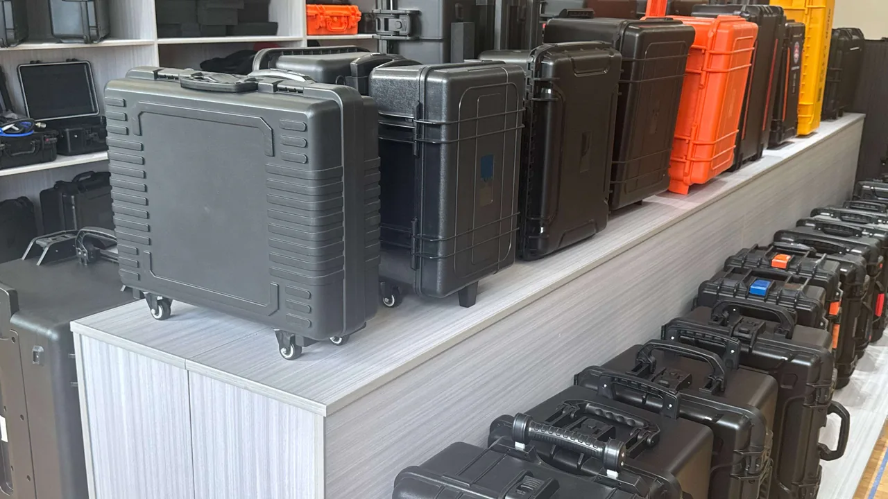
JUNZHIJIA's protection principle is straightforward: let the case structure absorb impact, vibration, stacking load and thermal swings first, so the instrument itself stays locked inside a micro-environment with zero displacement, zero condensation and zero dust ingress. A case built to that principle is not a shell. It is an engineered system in which shell stiffness, cushioning gradient, liner geometry and perimeter sealing each carry a defined share of the load.
Table of Contents
- Why Optometry Equipment Demands a Purpose-Built Protective Case
- Failure Modes Across the Transport and Handling Chain
- Shell Material and Structural Stiffness Selection Logic
- Sealing, Dust and Moisture Control: Choosing Between IP65 and IP67
- Cushioning Foam Systems and Gradient Liner Design
- Protecting Optical Elements and Optical Axis Stability
- Compartment Layout and Poka-Yoke Design for Trial Lens Sets
- Latch, Hinge and Pressure Equalization Valve Reliability
- Temperature, Condensation and Salt Spray Control Strategy
- Transport Testing, Acceptance Criteria and Metrology State Retention
- Stowing Accessories, Consumables and Shipping Documents
- Custom Tooling, OEM/ODM and Delivery Workflow
- Frequently Asked Questions FAQ
- Conclusion and Related Reading
Why Optometry Equipment Demands a Purpose-Built Protective Case
The problem with a general-purpose tote is never whether the instrument fits. It is what happens to the instrument after it fits. An autorefractor body typically weighs between 8 kg and 20 kg, and a fully populated trial lens set falls between 5 kg and 12 kg. That moderate mass, combined with a rigid floor panel and hard inner walls, creates an unforgiving mechanical path. Impact energy reaches the wall first, the wall behaves as a near-rigid body and dissipates almost nothing, and the energy then arrives essentially undiminished at the instrument's feet or shell edges before propagating inward toward the optical assembly. This rigid column is the worst possible excitation for precision optics, because it produces a short-duration, high-frequency pulse that lands squarely in the resonance band of optical mounts and lens barrels.
A purpose-built case breaks that path by inserting two or three stages of compliance. The first stage is elastic deflection of the shell and its reinforcing ribs. The second is compressive deformation of the foam liner, which converts kinetic energy into heat across a large volume. The third is controlled suspension of the instrument inside the cavity. In an ideal 1.2 m drop, the shell flexes recoverably first, clipping peak acceleration from thousands of g down to hundreds, and the foam then spreads the remaining energy across the contact area. Throughout that sequence the instrument should experience no meaningful relative movement, rather than bouncing around inside a void.
A second requirement is less obvious: metrological traceability. Refractors and trial lens sets are calibrated instruments whose readings feed directly into prescriptions. If transport conditions cannot be shown to have been controlled, a reading drift discovered on arrival becomes very hard to attribute. The case therefore functions as evidence as well as protection. An intact seal, unsaturated desiccant and unbroken tamper labels together form a chain of custody that a foam-lined carton can never provide.
In procurement practice, dropping a bare instrument into an ordinary plastic crate with bubble wrap looks economical until the first incident. Returning a phoropter with a mis-indexed turret normally involves teardown, component replacement, optical realignment, whole-unit verification and two freight legs. The combined cost usually exceeds the price of an engineered case several times over, which is why the low-cost option is rarely the cheap option. (Further reading: Precision Instrument Protective Cases)
Failure Modes Across the Transport and Handling Chain
Choosing the right case begins with understanding how instruments actually fail. Optometry equipment almost never arrives with a smashed shell. It arrives looking perfect and behaving badly, which is precisely what makes protection design so demanding. The table below maps typical failure modes to their transport triggers and the engineering countermeasures available.
| Failure mode | Trigger stage | Instrument-side symptom | Case-side countermeasure |
|---|---|---|---|
| --- | --- | --- | --- |
| Optical assembly shift | 1.2 m drop, throwing | Diopter drift, blurred imaging | Gradient foam plus locating steps limiting X, Y and Z travel |
| Turret and knob binding | Sustained vibration, resonance | Irregular feel, skipped detents | Tighter liner fit, eliminating unsupported spans |
| Lens surface scratches | Loose compartments, mutual contact | Coating damage, transmission loss | Individual slots with flocked or soft TPU walls |
| Motor and lead screw damage | Stacking pressure, lateral impact | Grinding focus, self-test errors | Ribbing and thicker sidewalls capping deflection |
| Mold bloom and coating haze | Marine humidity, condensation | Fogging, long-term fungal growth | IP67 sealing, desiccant and pressure equalization |
| Electronics failure from moisture | Thermal cycling, dew point | No power-up, dead keys | Metered desiccant, controlled unpack sequence |
| Label and nameplate wear | Repeated packing friction | Unreadable serial number, broken traceability | Recessed liner pockets avoiding face contact |
| Seal degradation | Prolonged UV exposure | Rain ingress, dust intrusion | Weather-resistant EPDM or silicone with controlled compression set |
These modes collapse into two families: displacement failures and environment failures. Displacement is solved by structure and foam, and its governing metric is residual movement of the instrument relative to the liner. Environment is solved by sealing and sorption materials, and its governing metric is the relative humidity inside the closed case and how long it can be held there. Because the two families share almost no countermeasures, thickening a wall does nothing for fungal bloom, and adding desiccant does nothing for a cracked turret.
One statistical reality also matters. Most damage does not occur on the long-haul leg. It occurs at the two ends, during manual handling and short transfers, when a forklift misjudges a pallet, a shoulder strap slips or a stack topples. A protection design must therefore be validated for repeated rough treatment, not only for a well-behaved freight lane. Latch anti-release geometry, corner over-molding and handle load paths often decide the outcome more than the liner material does.
Shell Material and Structural Stiffness Selection Logic
Copolymer polypropylene dominates optometry cases. Modified PP keeps useful toughness at low temperature, has low density and good chemical resistance, and keeps the empty case light enough to lift comfortably. Where higher impact loads or a wider temperature band must be covered, polycarbonate or a PC/ABS blend becomes attractive, at the cost of weight and price. Rotational molding suits large bodies because wall thickness is uniform and the shell has no seams, but dimensional accuracy and surface finish lag behind injection molding, which makes liner tolerance control harder. The table below compares the main structural options.
| Structure | Wall thickness | Low-temperature toughness | Dimensional accuracy | Typical optometry fit |
|---|---|---|---|---|
| --- | --- | --- | --- | --- |
| Injection molded copolymer PP with ribs | 2.5-4.0 mm | Good, down to about -20 °C | High, locating steps molded directly | Complete refractors, phoropters |
| Injection molded PC/ABS blend | 2.0-3.5 mm | Very good, down to about -30 °C | High | Premium refractors with electronics |
| Rotomolded PE | 4.0-8.0 mm | Very good | Moderate, needs secondary machining | Large bodies, multi-unit shipments |
| Aluminum frame with panels | 0.8-1.5 mm panels | Very good | High | Frequent air freight, weight-sensitive users |
Stiffness is less about making the whole box thick than about putting mass where it works. A practical distribution thickens the base and the rim, thins the mid-wall and adds longitudinal ribs, so the case can bend in a controlled way under impact. If every face is a rigid slab, the shock passes straight through. If every face is soft, the case sags under stacking load. JUNZHIJIA typically applies a thick base, thick rim, ribbed walls and reinforced corners, with generous external radii and over-molded corner pads so the corner absorbs energy first and the base then spreads it evenly.
One frequently overlooked detail is the inner surface itself. Draft angles, parting-line flash and sink marks at rib roots all affect how well the foam liner sits and how the instrument face contacts it. A refractor usually rests on four adjustable feet or rubber pads. If the slot floor is not flat but a dished surface with sink marks, the instrument sits on point contacts, and a drop concentrates stress directly into the foot threads. Good practice requires a flat contact face with at least 60 percent of the instrument footprint carrying load, achieved by die-cut or thermoformed liner detail. (Further reading: Instrument Case Selection Guide)
Sealing, Dust and Moisture Control: Choosing Between IP65 and IP67
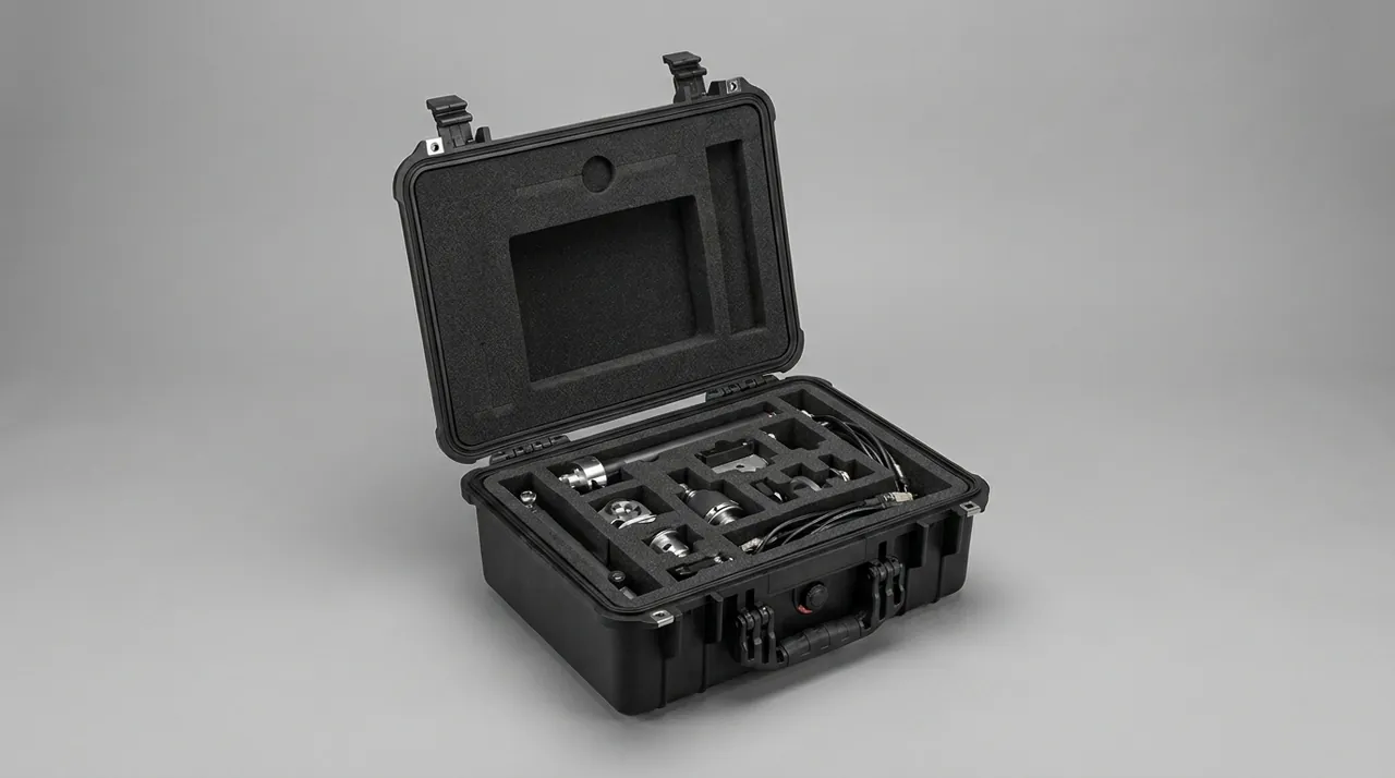
How much water resistance optometry equipment needs depends on the shipping lane and the storage environment rather than the purchase price. For short rain exposure on road or air legs, IP65, meaning dust-tight and protected against water jets, is usually sufficient. Marine container freight changes the calculation. Day and night temperature swings inside a container drive repeated condensation, and port yards can be hit by typhoon rain and wind-driven spray, so most refractor manufacturers simply specify IP67, meaning protection against temporary immersion. The rating is tested to IEC 60529 or the equivalent GB/T 4208, and its meaning must be read together with the test conditions rather than treated as an unconditional promise.
Sealing is achieved with one primary barrier plus several secondary ones. The primary barrier runs along the mating face of the two shell halves, normally an integrally molded silicone or weather-resistant EPDM gasket compressed by the closing action of the rim to form an unbroken contact band. Secondary barriers include localized compression features at each latch, the bidirectional seal of the pressure equalization valve, and the plugs closing cable or drain ports. Under immersion the corners are usually the weak point, because gasket material tends to lift there under internal stress. Vulcanized corner sections or mitered 45-degree joints are the standard remedy.
Moisture control is not simply a matter of closing the lid. Trapped humid air releases condensate as temperature falls, and that condensate deposits on the coldest surfaces, which are normally the metal lens barrels and coated optics. The standard approach is to control the dew point of the air at packing, then charge the cavity with enough desiccant for its free volume, using a canister with a visible humidity indicator. A working ratio is 20 g to 40 g of high-grade silica gel per 10 liters of free volume, taken at the upper end for long marine cycles with a scheduled replacement window. Where a pressure equalization valve is fitted, it vents automatically above roughly 2000 m elevation or in a depressurized air cargo hold, preventing the pressure differential from collapsing the gasket or creating a vacuum that draws moist air in at unpacking.
The table below summarizes sealing recommendations that can be copied directly into a tender document.
| Transport scenario | Recommended rating | Sealing approach | Additional measures |
|---|---|---|---|
| --- | --- | --- | --- |
| Local transfers between clinics | IP54-IP65 | Single gasket plus standard latches | Dust focus, valve optional |
| Domestic long-haul transfers | IP65 | Gasket, desiccant, breathable dust membrane | Humidity indicator card |
| International LCL sea freight | IP67 | Primary gasket, equalization valve, desiccant canister | Salt spray protection, outer crate |
| International air freight | IP67 | Primary gasket, pressure equalization valve | Verify gasket recovery at low pressure |
| High-altitude field deployment | IP67 | Primary gasket, equalization valve, reinforced latches | Gasket compound for wide thermal range |
IP67 certifies that a sample passed one immersion test under standard conditions. It carries no time dimension. Gaskets lose performance with age, ultraviolet exposure and compression set, so the contract should define the replaceable gasket design and its service interval. (Further reading: Protective Case Seal Materials)
Cushioning Foam Systems and Gradient Liner Design
Cushioning is where a protective case earns its engineering content. A refractor contains optical components that are sensitive to high-frequency shock, motors and lead screws that respond to low-frequency vibration, and coated lenses that are vulnerable to surface friction. No single foam density or thickness satisfies all three. The established solution is a density gradient: softer, lower-density material next to the instrument to absorb low-energy high-frequency input, and firmer, higher-density material near the shell to take high-energy impact and cap displacement.
Common liner materials and their behavior are summarized below.
| Material | Density band | Rebound behavior | Strengths | Limitations |
|---|---|---|---|---|
| --- | --- | --- | --- | --- |
| EPE pearl foam | 25-40 kg/m3 | High rebound, multi-event absorption | Low cost, easy die-cutting | Soft surface, creeps under long compression |
| EVA copolymer foam | 60-120 kg/m3 | Moderate rebound, good support | Thermoforms complex cavities, holds shape | Absorption drops at high density |
| Low-expansion PE foam | 30-60 kg/m3 | Moderate rebound | Balanced cost and performance | Accuracy depends on machining |
| IXPE cross-linked foam | 40-80 kg/m3 | Soft, conforming | Fine surface, low particle shed | Higher unit price |
| Viscoelastic PU sponge | 30-60 kg/m3 | Low rebound, conforming | Conforms to irregular faces, spreads contact stress | Hygroscopic, needs treatment |
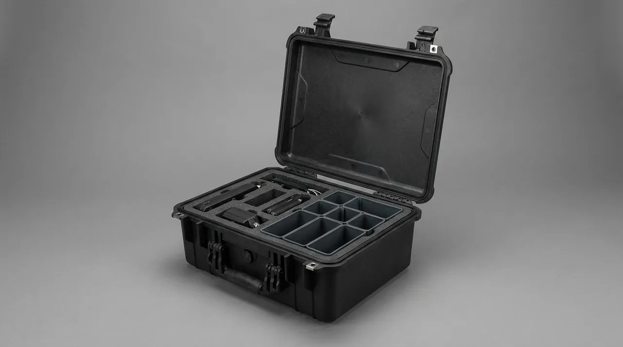
The recommended arrangement for a complete refractor is a dual-layer base, a single-layer perimeter and a compression layer at the top. The base carries the main impact, combining a thermoformed EVA shell with an EPE underlay so that EVA provides cavity definition and dimensional stability while EPE adds absorption. The perimeter uses flocked EVA or IXPE to follow the side profile and damp lateral shock. A thicker compression foam sits under the lid, using the preload created when the lid closes to clamp the instrument firmly and eliminate free travel in the vertical direction. For trial lens sets needing individual location, the liner becomes an EVA grid with one slot per lens.
Three acceptance criteria govern liner design: zero residual displacement, bounded acceleration and no hard points. Zero displacement means the instrument moves no more than 2 mm relative to the liner after the design impact and never escapes the cavity. Bounded acceleration means the peak value at critical locations such as the optical axis mounting face stays within the manufacturer's allowance, typically 40 g to 60 g. No hard points means the contact faces contain no metal, hard plastic or sharp unradiused edges, and every load path passes through elastic material. These criteria must be proven by drop test data rather than judged by hand. JUNZHIJIA normally starts from a 3D scan, builds a 1:1 sample liner, runs a physical drop sequence and only releases tooling once both displacement and acceleration figures pass.
Protecting Optical Elements and Optical Axis Stability
Optical axis stability determines whether an optometry instrument still measures correctly. An autorefractor works by projecting a target ring onto the retina and imaging the reflection, so any positional error among the objective lens, beam splitter and target plate converts directly into a diopter error. A phoropter builds its optical path from many lenses and turrets, and tilting or shifting any one element introduces aberration. The protection objective is therefore not an intact housing but an unchanged relative position between any two optical reference surfaces.
Three measures work together. The first limits whole-body rotation and pitch. An instrument free to rotate inside its case converts even a small displacement into a large relative movement of optical elements through a long moment arm, so the liner must constrain the front, rear and side faces simultaneously, adding a locating boss under the lid where necessary. The second locks rotating mechanisms. If a phoropter turret is packed away from its zero index, inertia during transport generates loads of different magnitude at different radii, so the packing instructions should require re-indexing before closure with a dedicated locking insert. The third suppresses self-excited vibration in lens stacks. If a lens can rattle in its slot, vibration appears as intermittent metal-to-glass contact, and over time that produces coating scratches and chipped edges, so slot width tolerance should be held within 0.3 mm.
Surface protection matters just as much. Modern refractor lenses carry multilayer antireflective coatings whose hardness is far below that of the glass substrate, so a single point of friction leaves a visible mark. Any surface touching a coated face must be clean, non-shedding and free of migratory plasticizers or sulfur compounds, since those react with some coating chemistries and cause haze. Clean-grade flocked EVA, sulfur-free PU foam or flocked fabric are the usual choices, and the liner specification should require cleaning before use so that no die-cutting dust remains.
Original dust caps or a custom cradle should also be retained. A significant share of repair cases trace back not to impact but to packing with an uncapped objective facing downward, pressing the coated surface directly into the liner. An asymmetric cavity eliminates this class of error by allowing only one correct orientation. (Further reading: Optical Lens Coating Cases)
Compartment Layout and Poka-Yoke Design for Trial Lens Sets
A trial lens set is the most part-dense, most tolerance-critical and most easily disordered item in the optometry kit. A complete set divides into spheres, cylinders, prisms, cross cylinders, occluders and accessories, arranged in diopter steps that can easily exceed 250 pieces. Three problems dominate during transport: collisions caused by clearance in individual slots, position swaps between adjacent slots that make verification painful on arrival, and missing lenses that nobody notices until a refraction is wrong.
The engineering answer is a monolithic EVA grid. Board thickness follows the lens plus a minimum handling clearance, slots are CNC die-cut or hot-pressed, and the wall between adjacent slots stays at least 6 mm thick to preserve rigidity. Directional lenses such as cylinders and prisms need either printed orientation marks or asymmetric slot geometry that admits only one correct placement. Components that must hold a handwheel angle, such as cross cylinders, deserve their own dedicated cavity rather than sharing a slot with flat lenses.
Poka-yoke, or mistake-proofing, works at three levels. First, slot identification: print or hot-stamp the diopter value directly onto the liner face so it matches the lens frame label and can be checked without removing anything. Second, a removable tray: make the entire liner lift out so a full set can be verified on a flat bench and replaced in one motion, avoiding the mis-ordering that piece-by-piece handling invites. Third, visible absence: use a contrasting slot floor or a flip indicator at each position so a missing lens is obvious at a glance.
Recommended parameters for trial lens set liner design are listed below.
| Design parameter | Recommended value | Rationale |
|---|---|---|
| --- | --- | --- |
| Per-side slot clearance | 0.15 mm or less | Prevents lens movement and mutual contact |
| Divider wall thickness | 6 mm minimum | Preserves grid rigidity under compression |
| Total liner thickness | Thickest lens plus 8-12 mm | Leaves room for top compression layer |
| Handling chamfer | R1.5 to R3 | Enables fingertip retrieval without jamming |
| Surface treatment | Flocked or fabric-faced | Reduces friction and particle shed |
| Slot count margin | 3 to 5 percent spare | Accommodates additions and replacements |
Trial lens sets carry one further risk: they travel as an accessory beside the refractor and are therefore the first thing a handler stacks something heavy on. If the liner is designed only for flat orientation, turning the case on its side shifts the whole set. Keeping preload between liner and lid so the lenses stay pressed in any orientation, and marking the shell with a "this side up only" transport label, solves most of it. (Further reading: Custom Foam Inserts)
Latch, Hinge and Pressure Equalization Valve Reliability
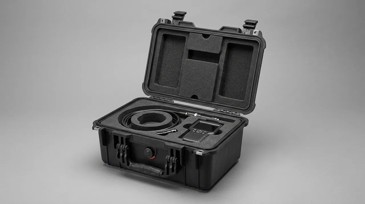
Latches are the only components holding the two shell halves together, and their failure carries the most severe consequences. Optometry cases normally use two or four draw latches that pull the reinforced rim into uniform compression. Design attention concentrates on three things: clamping force distribution, anti-release geometry and service life.
Clamping distribution decides whether the gasket is compressed evenly around the entire perimeter. Two latches placed at the middle of the long sides leave the ends under-compressed, and the corners are the first to leak. Good practice keeps latch spacing at 300 mm or less, or fits four latches along the long side and provides a rim beam with adequate stiffness. Where a side face can take load, the latch should include a self-locking feature so lateral impact cannot pop it open.
Hinges provide closure alignment and carry part of the load. A continuous piano hinge resists misalignment well, while separate hinges are easier to manufacture but demand tighter installation control. Verification should cover the replaceability of the hinge pin, its retention feature, and whether the stress at full lid opening is carried by metal rather than by the plastic body. Latch and hinge life is measured in open-close cycles, and 10,000 cycles with no more than 20 percent loss of clamping force is a reasonable engineering floor.
The pressure equalization valve is the component most often deleted and most often missed. It allows air to pass slowly whenever a differential builds between inside and outside while blocking liquid water and dust. For any case that will fly or cross significant elevation changes, the valve is close to mandatory. Without it, a depressurized hold can create a differential of tens of kilopascals, flattening the gasket or forcing it aside, and the shell may take a permanent set when pressure returns. Verification should address bidirectional flow, water resistance and installation sealing, normally by immersion under pressure while watching for leakage.
Suggested acceptance targets for key hardware are listed below.
| Component | Primary checks | Recommended target | Test reference |
|---|---|---|---|
| --- | --- | --- | --- |
| Draw latch | Cycle life, retention force | 10,000 cycles, less than 20 percent loss | Cycle test plus pull test |
| Hinge | Cycle life, axial play | 10,000 cycles, play under 0.5 mm | Cycle test plus feeler gauge |
| Equalization valve | Bidirectional flow, water resistance | Flow both ways with no ingress | Immersion under pressure |
| Handle | Static and dynamic load | Static load at least twice gross weight | GB/T 4857 series methods |
| Gasket | Compression set | Under 25 percent after 70 °C for 22 h | GB/T 7759 method |
A strong latch does not automatically make a strong case. If the rim beam lacks stiffness, tightening the latch distorts the rim locally and actually worsens gasket compression uniformity, so hardware selection has to be evaluated together with wall thickness and rib layout rather than optimized in isolation. (Further reading: Pressure Equalization Valve Guide)
Temperature, Condensation and Salt Spray Control Strategy
International sea freight is the harshest environment an optometry instrument will meet. Across latitudes, a container cycles through daytime interior temperatures above 50 °C and nighttime lows below 10 °C. Residual moisture inside the case condenses during the cooling phase and deposits on metal lens barrels, and prolonged exposure leads to plated-layer corrosion, seized threads and coating haze. Salt spray arrives from port yards and open sea as an extremely fine, highly penetrating aerosol that attacks latches, hinges and any exposed metal.
Control runs along two lines: block and absorb. Blocking depends on sealing class and structural design. Gasket material should be weather-resistant EPDM or silicone rather than ordinary NBR. Metal parts should carry a surface treatment with a defined salt spray class, with no red rust after 48 to 96 hours of neutral salt spray testing to GB/T 10125 as a common threshold, and external metal should be minimized or specified in stainless steel. Absorption depends on desiccant and humidity indication: charge the cavity according to free volume and include a visible indicator card or color-change silica gel so that the state of the interior is known the moment the lid opens.
Low-temperature brittleness also belongs in this discussion. Some plastics lose impact toughness sharply below -20 °C, so a case crossing cold regions or riding in a refrigerated hold should use a low-temperature grade or a PC/ABS blend, verified by a cold drop. A common protocol freezes the assembly at -25 °C for four hours and drops it while still cold, checking for shell cracking or brittle latch failure.
Note that a salt spray hour figure is valid only for the specific coupon and conditions tested. The contract should state coupon material, surface treatment process, test standard and acceptance criteria, together with the boundary that results apply only to undamaged surfaces with uncut edges. Desiccant service life should be stated on the same basis and a replacement interval given in the documentation.
Environmental control configurations matched to typical sea routes are shown below.
| Environmental factor | Peak-risk condition | Control configuration | Verification method |
|---|---|---|---|
| --- | --- | --- | --- |
| High humidity | Relative humidity above 85 percent for long periods | IP67 sealing, desiccant canister, indicator card | Immersion test plus humidity logging |
| Condensation | Day-night swing above 15 °C | Low dew point at packing, generous sorbent | Cyclic temperature and humidity chamber |
| Salt spray | Coastal yards, open-sea air | Salt spray rated metal, sealed isolation | GB/T 10125 neutral salt spray |
| Low temperature | Below -20 °C | Low-temperature grade material, cold drop | Drop after freezer conditioning |
| High temperature | Above 60 °C inside the hold | Temperature-stable foam, creep-free liner | High-temperature storage plus dimension check |
Transport Testing, Acceptance Criteria and Metrology State Retention
Case performance must be demonstrated with data rather than described. An optometry case normally has to clear three test families: package drop, vibration and stacking compression. Drop testing generally follows an ISTA procedure or GB/T 4857.5, with drop height and orientation set by package weight and coverage of edges, corners and faces. Vibration testing follows ISTA or GB/T 4857.7 using fixed-frequency or random methods to expose resonance and loosening. Stacking testing follows GB/T 4857.3 and evaluates creep deformation under tall stacks and warehouse storage.
For optometry equipment, acceptance cannot stop at an undamaged case. Instrument-side criteria must be added, and they fall into appearance, function and metrology layers.
| Criterion layer | Inspection item | Pass condition |
|---|---|---|
| --- | --- | --- |
| Appearance | Cracking, latch failure, liner shift | No service-affecting cracks, latches function correctly |
| Displacement | Residual movement against the liner | 2 mm or less, no escape from the cavity |
| Function | Self-test, turret feel, focus travel | No error codes, feel matches factory condition |
| Metrology | Standard model eye reading, lens verification | Within the manufacturer's stated tolerance |
| Sealing | Immersion or airtightness retest | No leakage, desiccant not prematurely saturated |
Maintaining metrological state depends on process discipline. Packing documentation should include a pre-shipment checklist covering optical-axis restraint of moving parts, lens cap installation, foot locking or removal, separate restraint of accessories and desiccant condition. On arrival, an acclimatization sequence should apply: let the case rest at room temperature for two to four hours before opening, so that condensate does not form as moist air rushes in, then check displacement evidence before powering up.
Procurement and acceptance should also define responsibility boundaries and traceable elements. Case serial number, desiccant replacement date, gasket service interval and test report number together form a complete evidence chain for instrument transport. For high-value refractors, binding one instrument to one case and one serial number, with QR-coded records of every trip and service event, is worth the small administrative effort it costs. (Further reading: Transport Vibration Testing)
Stowing Accessories, Consumables and Shipping Documents
The accessory load that travels with an optometry instrument is far more varied than the instrument itself: power adapters and cables, printer paper rolls or thermal modules, chin rest papers, dust covers, a standard model eye for calibration, spare ribbons, plus the certificate of conformity, calibration certificate, packing list and warranty card. Stowing these in the same cavity as the instrument creates three distinct risks. Cables can wrap around an operating control and apply an unintended pull. Small accessories can migrate freely and act as loose projectiles against coated surfaces. Paper documents can absorb moisture and become a humidity source inside an otherwise well-sealed cavity.
The standard solution is a three-zone layout: main cavity, side cavity and document cavity. The main cavity holds only the instrument, located by its molded liner. The side cavity holds cables, adapters and consumables in shallow pockets with elastic retainers, and cable channels are dimensioned by coil diameter so that no cable is bent below its minimum radius. The document cavity sits outside the primary sealed volume, or in a separate sleeve inside the lid, so that paper cannot influence internal humidity while remaining accessible on opening.
A combined shipment of refractor and trial lens set can be handled either as one case with two cavities or as a main case plus a companion case. The dual-cavity approach reduces handling events because both instruments move together, but it raises gross weight and volume and demands verified handle capacity and stack stability. The companion case is more flexible, allows independent protection levels and permits separate handling, at the cost of extra pieces and a higher risk of one going missing. The right answer depends on how the clinic actually moves equipment, not only on case cost.
A shipping document set is itself a deliverable. A practical list includes a packing diagram marking every item position, a statement of liner clearances and allowable acceleration, the desiccant replacement interval, the gasket inspection interval, transport orientation labels and the acclimatization procedure. A single clear document frequently prevents more repairs than an extra millimeter of foam. (Further reading: Medical Instrument Cases)
Custom Tooling, OEM/ODM and Delivery Workflow
Optometry models refresh quickly and their outlines change substantially, so a catalog case rarely stays suitable for long and custom work becomes the norm. A custom program starts with requirements definition: instrument model and envelope dimensions, mass and center of gravity, known vulnerable areas, transport mode and route, target IP rating, stacking height and the accessory list. Engineering follows with 3D scanning, liner cavity design, case selection or tooling design, drop and vibration simulation, and a 1:1 prototype validated physically. Once the prototype passes, production covers mold sign-off, first article inspection, batch manufacture and outgoing inspection.
Where an entirely new shell is required, tooling cost and lead time dominate the decision. Upfront investment covers mold design, mold base machining, cavity machining and trial shots, normally amortized over order volume. If the liner changes but the shell can stay on a mature platform, only a liner mold or CNC machining is needed, which cuts cost sharply and shortens delivery. In procurement, deciding early whether the project is a shell customization or a liner customization saves substantial money. Under ODM arrangements the supplier can join the definition phase and advise on case dimensions, strength and stacking, preventing a situation in which the customer fixes an outline and is then forced to accept a structural weakness.
Delivery should define first article inspection records, dimensional sampling reports by batch, sealing and drop test reports, liner material certificates with cleanliness statements, and the documentation and markings that must ship with the goods. Where calibrated instruments are involved, the correspondence between case serial number and instrument serial number should be established and a label position reserved on the shell. JUNZHIJIA supports optometry programs end to end, from structural design and liner prototyping through drop validation and volume delivery, including brand hot stamping, color customization and shipping documentation packs, and can operate under OEM or ODM models as required.
Key milestones and deliverables for a custom program are summarized below.
| Stage | Main activity | Deliverable |
|---|---|---|
| --- | --- | --- |
| Requirements | Instrument data, route, rating targets | Confirmed requirement and technical specification |
| Design | 3D modeling, liner cavities, simulation | Drawings and simulation report |
| Prototype | 1:1 liner, fit check, drop and vibration | Sample, test records, issue list |
| Tooling | Mold sign-off, first article inspection | First article report and mold acceptance |
| Production | Molding, liner fabrication, assembly | Sampling report and production records |
| Delivery | Marking, documentation, packing | Packing list, certificate, test reports |
Frequently Asked Questions FAQ
Q: Does a refractor need an IP65 or an IP67 case for transport?
A: The right answer depends on the water exposure of the route, not on the value of the instrument. For transfers between clinics or within a city, dust and spray resistance are the main concerns and IP65 is sufficient, provided the case has one reliable gasket and conventional latches. For international less-than-container sea freight, long port yard storage, or routes through rainy and coastal regions, specify IP67 and add a desiccant canister, a humidity indicator card and a pressure equalization valve. The reason is that the day-night temperature cycle inside a marine container produces continuous condensation, so raising the sealing class addresses sustained ingress of liquid water and humid air, while condensation itself still requires desiccant to control. Whichever rating is chosen, the contract should state gasket material, replaceable design, recommended service interval, and the exact test conditions behind the rating report, and maintenance planning should include periodic gasket inspection. For a tender document, state the required class together with the shipping route and storage conditions, because a higher rating adds weight, cost and latch loading and should be justified rather than specified by habit.
Q: Why is a refractor that cannot move at all inside its case not necessarily well protected?
A: Because rigid restraint and shock transmission have to be balanced. If the instrument is clamped absolutely rigid, impact energy reaches the structure without passing through any compressible medium, so peak acceleration becomes very high and the optical mounts and optical axis faces take the load first. The correct approach keeps a small, controlled amount of elastic travel in the critical directions. The liner should locate the instrument without rigidly gripping it, letting foam compression absorb energy and holding peak acceleration at critical points within the manufacturer's allowance, typically 40 g to 60 g. At the same time the movement must stay very small, with residual displacement after impact normally required to remain under 2 mm and the instrument never escaping its cavity. The engineering target is controlled compliance rather than absolute rigidity, and it has to be proven with drop test data covering both acceleration and displacement. A useful rule is to specify the allowable acceleration at the optical axis mounting face, and to state clearly whether that figure applies to the instrument alone or to the packed assembly.
Q: After transport, the coated lenses in a trial set show fine scratches. What usually causes this?
A: In most cases the cause is not excessive impact but a mismatch between slot clearance and contact material. If per-side slot clearance exceeds roughly 0.2 mm, vibration makes the lens move repeatedly inside the slot, so the coated face makes intermittent contact with the slot wall and develops a dense pattern of fine scratches over time. If the wall material contains migratory plasticizers or sulfur compounds, a chemical interaction with the coating can additionally produce haze. There are three remedies. First, hold per-side slot clearance to 0.15 mm or less, using an elastic slot floor to absorb manufacturing tolerance. Second, specify clean-grade flocked EVA or flocked fabric for the slot walls, with no shedding and no leachable substances, and require cleaning after fabrication to remove die-cutting dust. Third, maintain enough preload between the liner and the lid that the lenses stay pressed down in any orientation, so a brief period on its side does not shift the whole set. Ask the liner supplier for the material's leachable content declaration, not only for its density grade.
Q: How does JUNZHIJIA verify zero displacement in an optometry liner design?
A: Through a closed loop of modeling, prototype and measurement rather than experience and feel. The first step is a 3D scan of the instrument, producing a complete model that includes controls, feet, connectors and vulnerable faces, which then drives the cavity and restraint surface design. The second step is a 1:1 prototype liner, loaded with the instrument and fitted with marker points at critical locations, followed by a static fit check to confirm contact and handling. The third step is physical drop and vibration testing. Drops follow package-weight-derived heights and cover corner, edge and face orientations, vibration uses fixed-frequency or random methods, and marker positions are measured before and after to determine whether residual displacement stays within 2 mm. Accelerometers at critical points confirm peak acceleration against the manufacturer's allowance. If the figures fail, the gradient structure and restraint layout are revised rather than the foam being simply thickened. Marker measurement should be repeated after each of the three drop orientations, so that one severe orientation cannot be hidden by averaging across the set.
Q: Is a pressure equalization valve genuinely necessary for optometry transport?
A: For instruments that will fly, cross significant elevation changes, or spend long periods in sea freight, it is close to a required component. The better a case is sealed, the more pronounced the differential problem becomes. A depressurized cargo hold pushes the gasket outward, and in extreme cases lifts it off its seating. After landing or unloading, external pressure recovers and the interior goes into slight vacuum, so moist outside air is drawn in rapidly at the moment the lid opens, which is exactly when condensation forms if the instrument is below its dew point. A pressure equalization valve removes that differential by allowing slow bidirectional air movement while a hydrophobic breathable element blocks liquid water and dust, protecting both the gasket and the instrument. Three points should be checked at selection and acceptance: bidirectional flow rate under rapid pressure change, water resistance under immersion and pressure, and the integrity of the valve-to-shell seal. Where the valve is omitted, document that decision explicitly in the technical file so the resulting maintenance burden is visible to the operator.
Q: After sea freight, the optics are fogged on arrival. Does that prove the case failed?
A: Not directly. The first task is to distinguish external ingress from internal condensation. If the gasket is intact, there is no water staining, the desiccant is not saturated and the indicator shows normal, then fogging most likely comes from residual internal moisture released as temperature fell, which points to packing procedure and desiccant sizing rather than sealing. If the gasket is unevenly compressed, lifting at a corner, the inner walls show water marks, or the desiccant is fully spent, then sealing or sorption capacity was inadequate. A useful investigation order is to read the peak history on the humidity indicator, then examine gasket compression set and corner contact, and finally compare packing dew point and desiccant charge against cavity free volume. Corrective action means recalculating desiccant by free volume, typically 20 g to 40 g of silica gel per 10 liters taken at the high end for long sea legs, and improving the packing environment. A useful preventive measure is to log internal humidity with a small data logger on the first shipment of any new route, then size the desiccant from measured data rather than from a table.
Q: Where do custom optometry case projects most often exceed budget?
A: Most commonly the project is misclassified as full shell tooling when only the liner needed to change. Many programs can stay on a mature case platform and redesign just the liner and part of the hardware, which concentrates spending in CNC machining or a liner mold, shortens the schedule and keeps cost predictable. If the work starts from an entirely new shell outline, the customer takes on mold design, mold base and cavity machining, trial shots and rework, all of which must be amortized across order volume. A simple test resolves this early: check whether the instrument envelope fits an existing case cavity with adequate cushioning thickness. If it does, customize the liner first. If it does not, evaluate whether adjusting case height or adding external corner protection can avoid tooling altogether, and lock requirements before prototypes are cut. The safest sequencing is to freeze the instrument envelope, the transport route and the accessory list in a single requirements review, then validate the prototype against that baseline, because changes made after tooling release are the ones that destroy both budget and schedule.
Q: What routine maintenance does an optometry protective case need?
A: Maintenance is about keeping sealing and sorption capability inside their effective range instead of waiting for a failure. A practical cycle begins with gasket inspection before and after every long trip, looking for compression marks, cracks, lifted corners, surface hardening or embedded grit, with immediate cleaning or replacement when anything is found. Desiccant should be checked or replaced on the recommended interval, usually three to six months and shorter in humid regions, together with the humidity indicator card. Latch and hinge feel and clamping force should be checked periodically, and any hardware showing clear force loss or looseness should be replaced. The liner should be inspected for crushing, distortion, particle shed or local collapse, especially where it carries load against instrument edges. A case log recording serial number, trip count, desiccant dates and gasket replacements keeps the traceability chain intact. Keep that record with the case rather than only with the instrument file, so the two histories can be compared whenever a reading drift is investigated.
Conclusion and Related Reading
Optometry transport protection shifts uncertainty from instrument to case. Shell stiffness governs entry, cushioning gradient governs absorption, liner geometry governs displacement, sealing governs optical survival.
Related Reading