

A folder is the most intimate machine on the finishing line. The web is creased here and cut here, so a deviation of one millimetre at either operation is amplified downstream into crooked fold positions and spines that vary in thickness from booklet to booklet. The folding roller and the knife are also the two most vulnerable parts on the machine. The glue roll cover dents easily, ages quietly and collects rubber powder, while the knife edge chips, corrodes and runs out of true. When a folder moves from one printing house to another, the rollers and blades taken off the frame are frequently ruined before they are reinstalled: the cover carries a flat spot, the Shore hardness has quietly risen, and every batch folded afterwards comes out weak.
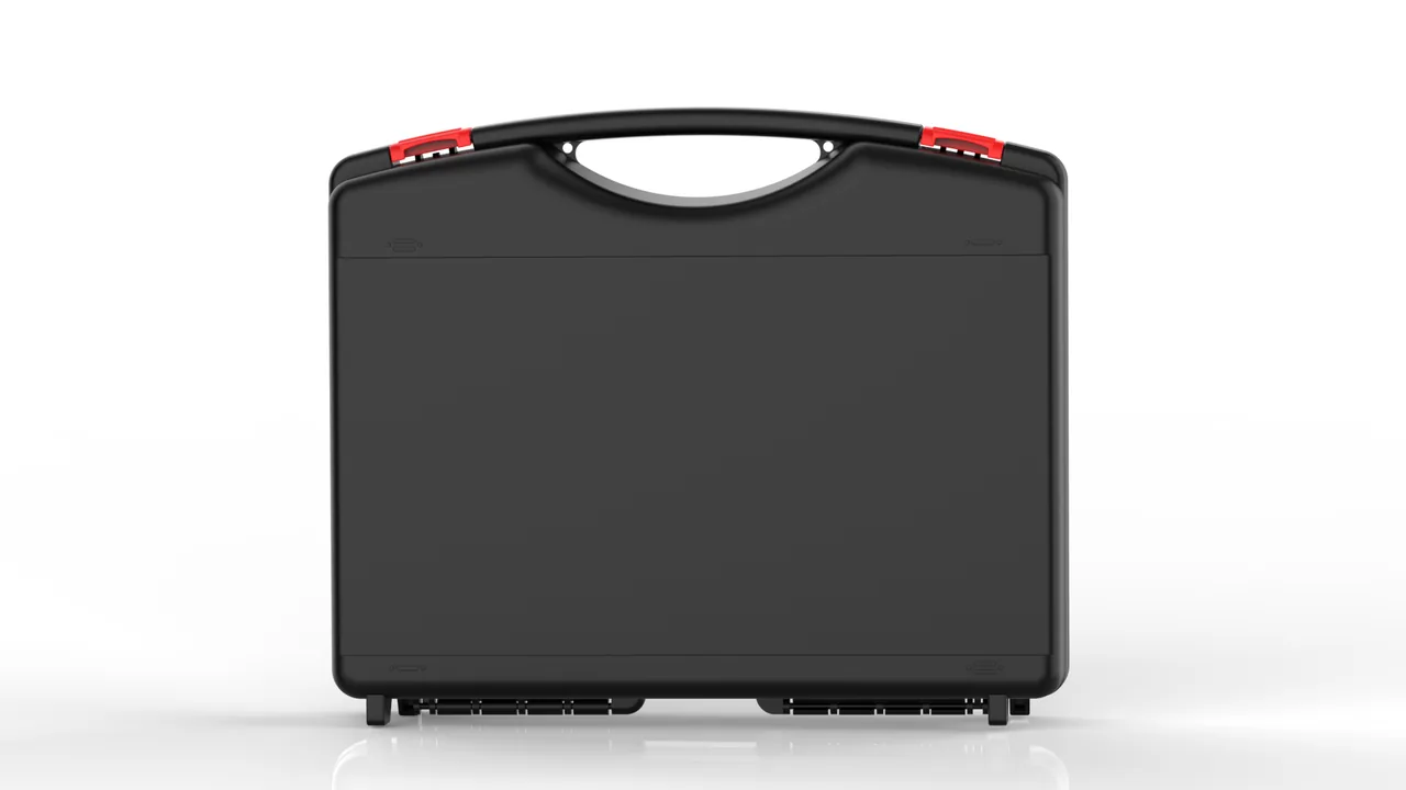
JUNZHIJIA holds that protecting folding rollers and knives is not a matter of choosing a shell that absorbs a drop. It requires liners and packaging designed against the failure mechanism of each part: rollers suspended clear of all contact, blades compartmented one per cell with rust protection, the paper path sealed against paper dust, and a register verification performed both before packing and after arrival. That principle is the basis for every structural choice described below.
Table of Contents
- Hardness Loss and Ageing Criteria on Folding Roller Covers
- Residual Nip Pressure and Dent Removal on Roller Faces
- Chipped Edge Detection and Blade Change Interval Management
- Maintaining Blade Shaft Concentricity and Blade Runout
- Paper Dust Ingress into Linear Guides and the Wear Mechanism
- Register Deviation Caused by Moisture Curling and Static Adhesion
- Coated and Matte Coated Stock: Different Wear Behaviour on Glue Rolls
- Blade Rust Protection and Coating Selection
- Anti-Dent Liners and Suspended Support Geometry
- Paper Path Cleaning and Adhesive Residue Removal on Arrival
- Register Verification Before and After Packing
- Cycle Time and Spare Part Management for Continuous Running
- Frequently Asked Questions FAQ
- Conclusion and Related Reading
Hardness Loss and Ageing Criteria on Folding Roller Covers
Folding rollers fall into two families: glue rolls with a polyurethane or rubber covering, and steel rolls. The glue roll is a consumable and the lowest cost part on the machine, yet the one most often destroyed in transit. Polyurethane covers normally run at Shore A 70 to 80 with a thickness of 8 to 15 mm, and they form the crease directly under line pressure. Each pass takes a little friction away from the cover while rubber powder builds up on the surface.
Three ageing paths run at the same time. The first is thermo-oxidative ageing: above 40 degrees Celsius the polymer chain breaks down, the surface loses its gloss, develops hairline crazing, and finally hardens and cracks. The second is ozone and ultraviolet attack, which erodes the ether bonds in the polyurethane. The third is stress relaxation: under a sustained line pressure of 0.3 to 0.6 MPa the rubber chains creep, so hardness and rebound fall together and the fold no longer springs back. Field judgement should rely on data: take three readings on each roller, one at the centre of the face and one 150 mm from each end, using a Shore A durometer, and compare the mean with the factory record.
| Ageing symptom | Field criterion | Effect on folding accuracy | Action |
|---|---|---|---|
| --- | --- | --- | --- |
| Gloss gone, patchy haze | Visual plus a gritty feel | Friction rises, the web drags | Grind or replace the roll |
| Shore hardness up by 5 A or more | Mean of three readings | Crease turns brittle, fold line cracks | Replace the cover |
| Fine surface crazing | Inspection at 10x magnification | Adhesive builds up in the cracks | Replace immediately |
| Rebound falls, fold does not return | Unload after creasing, measure recovery | Booklet opens, spine looks hollow | Replace the roll |
| Hardened edge cracking | Walk the roller face perimeter | Bright line along the fold position | Replace the roll |
Packaging slows the ageing rate; it cannot stop it. The roller face must be completely isolated: never next to a steel clamp plate or flange, never pressed by foam, never stacked. The JUNZHIJIA approach gives every roller an annular liner sized to the roller shoulder, with low-friction nonwoven cloth at the contact face and closed-cell foam filling the remaining cavity as an axial restraint. The case must also be kept away from heat, since a metal vehicle wall can exceed 60 degrees Celsius in the afternoon, enough to harden a 70 A polyurethane noticeably within two weeks.
Residual Nip Pressure and Dent Removal on Roller Faces
Folder nip pressure is generated pneumatically, hydraulically or by mechanical springs. All three leave behind the same thing when the machine stops: pressure that was never released. That residual load is the direct source of roller face dents. When a machine is stripped for relocation, the crew often pulls the journals, removes the bearings and lifts the roll out, then forgets to release the pressure. The roll is laid on the workshop floor while the load is still trapped inside the cover. A polyurethane roll held at 0.4 MPa in one spot for 72 hours develops a permanent dent between 0.1 and 0.3 mm that does not recover.
The consequence is not a cosmetic mark. Under load the dented zone becomes a full-width support point, so the web is creased harder there than anywhere else, and when unfolded a visible light and dark fold line appears. An automatic folder also skips and jumps, because friction in the dented zone runs 20 to 40 percent higher than on the surrounding surface.
Strip-down therefore follows a fixed order. Release the pressure before removing the roll: close the pneumatic valve, crack the bleed manifold and confirm the gauge reads zero, or open the hydraulic unload valve fully and watch for thirty seconds with no rebound. Never let two rollers lean face to face against a wall; they belong side by side in the same direction with at least 80 mm between faces. Never lift a roller by its journal, because the reaction puts a stress concentration at the shoulder and the bond line between cover and core fails first. Confirm by eye and by touch before packing: any step or hollow under a fingertip means the roller does not go in the case.
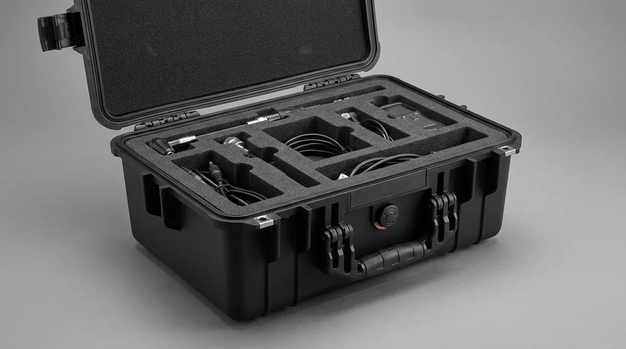
The liner exists so the face touches nothing for the whole transport cycle. Three layers are typical: a 2 mm closed-cell foam against the face for even support, an 8 to 12 mm low density cushion to absorb acceleration, and a rigid restraint block outside that carries the stacking load and routes it into the journals. These layers must have non-overlapping load areas, because any slack zone in the middle layer will pump under vibration and progressively enlarge a dent that started small.
Chipped Edge Detection and Blade Change Interval Management
The cutting system of a folder normally uses a pair of circular knives. The lower knife is fixed on the knife shaft, the upper knife sits in the pressure arm, and the shaft is carried in bearings in the frame. Knives are commonly DC11, SKD11 or high speed steel, mirror finished, with an edge angle of 30 to 45 degrees and a diameter of 400 to 700 mm. What the edge experiences in service is not clean cutting but alternating impact: every stroke produces a micro chip, and once enough accumulate the chip breaks away and the cut edge shows burr and tear marks.
Chipping can be judged without instruments. Sweep a fingertip along the edge in the axial direction: a good edge feels continuous and smooth, while the first hint of a chip feels as a faint catch. Examine a cut sample against oblique light, where white fringing, drawn fibres or an interrupted cut line give away an edge on its way out. In production the cleanest indicator is burr height: a sound knife trimming coated offset paper holds the burr between 30 and 50 micrometres, and once it exceeds 80 micrometres the knife must come off.
Change intervals depend heavily on the stock:
| Paper type | Typical interval | Dominant chipping cause | What to inspect |
|---|---|---|---|
| --- | --- | --- | --- |
| Coated offset | 160,000 to 240,000 cuts | Paper debris crushed at the edge | Glossy spots, fibrous burr |
| Matte coated stock | 80,000 to 140,000 cuts | Coating particles abrading the edge | Micro notches, coating residue |
| Heavy coated stock | 60,000 to 100,000 cuts | Hard coating striking the edge directly | Chip depth, shaft runout |
| Card and greyboard | 30,000 to 60,000 cuts | Hard fibre impact, debris in the gap | Broken chips, parallelism |
| Kraft with inclusions | 20,000 to 40,000 cuts | Foreign particles embedded in the edge | Edge debris, tip breakdown |
Knife control has to be a written record. JUNZHIJIA supplies a knife history sheet with the case documents, one line per knife giving the knife number, edge diameter, installed position, fitting date, accumulated cuts, reason for removal and chip rating at removal. Knives are stored by number in a compartmented box, one knife per cell, because stacking invites edge collisions at every transfer. Knives are changed as a set: replacing only one of the pair leaves a diameter difference that shifts the cut line, so both new knives go in during one event and the pair is ground into the same deviation band.
Maintaining Blade Shaft Concentricity and Blade Runout
Straightness and parallelism of the cut depend on the bearing condition of the knife shaft, the shaft deflection and the clamping stiffness of the knife. Together these produce blade runout, which shows up as a periodic drift of the cut line position. A folder holds register to the millimetre, yet blade runout has to stay within 0.05 mm to deliver that consistently.
Three transport factors are easy to overlook. The knife shaft is a long slender cantilever, and a shaft of 60 to 90 mm diameter and 800 to 1200 mm length will deflect if a side load acts on it in transit. That bending stays in the bearing seats, so the shaft runs true for a short while and bows again as soon as it is loaded. The bearings themselves are easily lost during strip-down, and fitting one bearing of the correct designation but a different internal clearance suddenly multiplies runout. Finally, adjustment shims at both ends of the shaft acquire slight plastic deformation under long clamping, so the original compensation no longer holds after reassembly.
The design rule for this part is simply: do not let it move. The knife shaft assembly gets its own cell. Side load is taken at the journal ends by close fitting liners, axial location by the end cap register, and the shaft body itself keeps 5 to 10 mm of clearance with no hard contact. Bearings occupy a separate small cell, each wrapped in rust inhibiting paper and labelled with its clearance group, and the fitting record travels with the case. Rust control on the shaft matters most, so the body is brushed with protective oil and sleeved in an inhibiting bag with desiccant inside.
Arrival verification follows a fixed order. Turn the shaft by hand with no paper threaded first and look for binding or noise. Then mount a dial indicator and measure runout axially and radially at three positions, 100 mm from each end and at the centre; the largest of the three readings is the runout of that shaft. If it exceeds 0.05 mm, investigate the bearings and the clamping before touching the knife grinding.
Paper Dust Ingress into Linear Guides and the Wear Mechanism
The most underestimated contamination source in a printing plant is not water but paper dust. It consists mainly of talc and calcium carbonate, typically 5 to 50 micrometres across, and shaped as extremely thin flakes. It is exceptionally slippery, so it enters any gap the eye cannot see, and it is hard: talc sits near 1 on the Mohs scale but calcium carbonate is around 3, and mixed with metal swarf it forms an abrasive three-body slurry.
The paper path of a folder exposes several linear guides: the infeed and outfeed guides around the folding rollers, the slide on the upper knife pressure arm, the guides of the register correction unit and the support rails beneath the stacking table. Most are open structures protected only by wipers or a secondary dust cover, and once a cover is broken or fitted badly, dust is dragged into the race on every stroke.
The failure path after ingress is short. The three-body grains roll along the race and plough grooves into its surface. Once groove depth exceeds the film thickness, metal contacts metal and the wear rate rises by an order of magnitude. Guide resistance climbs with it, the register unit starts alarming repeatedly, and the stroke ends with creeping stalls. The complaint is described as a folder that drifts worse with every repair, when the real cause sits in the guide.
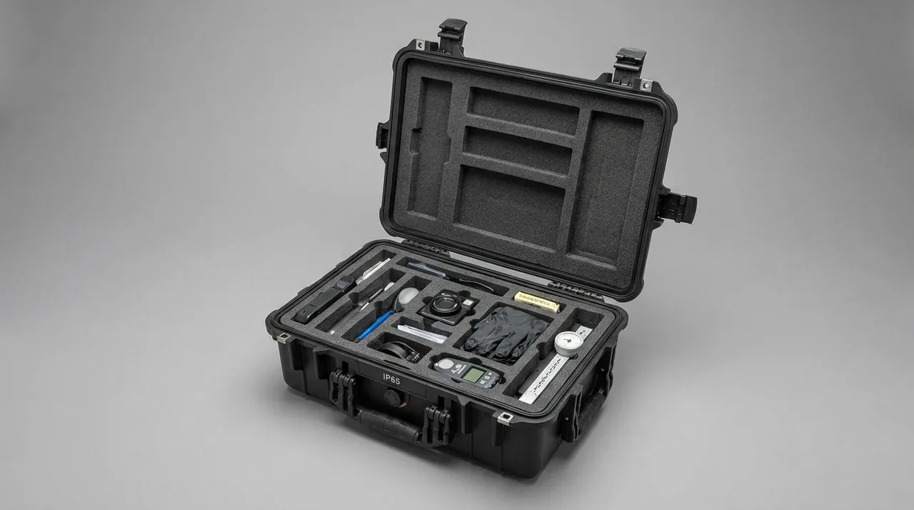
Three measures apply at the packing stage. Guides must be cleaned and their dust covers refitted before packing, and the case must contain no paper samples, shims or labels. The case sealing should reach at least IP6X as defined in IEC 60529 and GB/T 4208, meaning dust tight; the comparison between levels is covered in the difference between IP65 and IP67. A divider should separate the paper path zone from the opening zone, so positive pressure at the lid does not blow plant dust into an already packed guide cavity. Roller and guide packaging should not be split into two unrelated cases, because the effect of dust on accuracy is usually indirect, transmitted through inadequate cleaning.
Register Deviation Caused by Moisture Curling and Static Adhesion
A folder is extremely sensitive to ambient humidity. Paper reaches its most stable moisture content between 5 and 8 percent, where fibre swelling balances shrinkage. Below 35 percent relative humidity the paper loses moisture and its edges lift; above 65 percent it takes up moisture and the edges droop and curl. Both deformations become infeed skew and fold position offset, and the offset is not stable: it changes with the position of the reel, the batch and the sheet orientation, which is why a folder may run fifty sheets perfectly and then drift for the next fifty.
Curl develops readily during transport. A web travelling from the press to the folder and onward to binding often spends a night in an uncontrolled vehicle body. Condensation forms on the sheet surface, water is trapped between the plies, and by the time the reel reaches the destination the moisture gradient between core and surface is already established. Feeding it straight into the folder produces uneven web tension, and the register unit burns out its travel trying to hold it.
Moisture control is a configured system, not a gasket. Desiccant must be calculated from the cavity volume and the intended storage period rather than dropped in as a single sachet; anything stored beyond three months is sized from the humidity limit and then given a factor of 1.5 margin. A humidity indicator card travels in the case so the receiver can judge the internal state on arrival without opening anything. Equalisation time must be respected: reels stand 24 to 48 hours at 45 to 55 percent relative humidity before production. Static must be managed together with humidity, because coated paper generates high static at low humidity and the charge makes the web stick to the roller, adding wrinkles and crease splits. General storage moisture guidance is covered in warehouse stacking and moisture control cases.
Coated and Matte Coated Stock: Different Wear Behaviour on Glue Rolls
A folder does not run one stock. The action of the medium on the glue roll differs sharply, and the protection approach changes with it.
Matte coated paper carries a fine satin coating, usually calcium sulphate or calcium carbonate based with a little binder. It feels soft and has a high friction coefficient. Coating particles break off during creasing and transfer onto the cover, building a mixed film of coating powder and rubber powder. In the short term that film raises friction and crease roughness; over time it changes the pressure distribution across the fold. Cleaning with a steel scraper is the classic error: it takes the surface layer of the cover with it, and while the roll looks clean it has actually lost 0.2 to 0.3 mm of radius, which shifts the fold position.
Coated paper, including offset and light coated, has a harder and denser coating and forms a hard-on-soft contact with the cover. It transfers far less onto the roller but causes more abrasive wear: hard particles are pressed into the cover and plough fine furrows, and the cumulative result is loss of the gloss layer and a rise in hardness.
| Medium | Dominant roller failure | Transfer onto roll | Cleaning prohibition | Folding behaviour |
|---|---|---|---|---|
| --- | --- | --- | --- | --- |
| Matte coated paper | Coating build-up, friction rise | Coating and rubber powder | No steel scraper | Rough crease, prone to wrinkle |
| Coated stock | Abrasive grain wear, hardening | Minimal transfer | No hard bristle brush | Crisp crease, pressure sensitive |
| Coated offset | Mild friction wear | Paper debris | No compressed air blast | Generally stable |
| Uncoated offset | Fibre drop-out from weak sheet | Paper fibre | No dry wiping | Sheet breaks, edge fuzz |
| Kraft | Impact and cut from inclusions | Wood fragments | No hard tools | Notch at the fold position |
Rollers running matte coated stock should use a softer polyurethane at 60 to 70 A with a shorter cleaning interval, while rollers running coated stock should take a wear resistant formulation at 80 A or above so surface roughness does not spoil crease uniformity. Cleaning products and liners must never be shared between the two families, because coating powder left in a liner will contaminate the cover of the next roll. One liner per roller, never rotated between rollers.
Blade Rust Protection and Coating Selection
The number one reason a circular knife is scrapped is often corrosion rather than chipping. A mirror finished edge sits in a highly active surface condition, and the carbide and matrix phases in the edge region corrode readily in a damp environment. Corrosion starts at the edge as light brown to dark brown spotting that feels slightly rough, and if allowed to develop it produces edge notches and block chips. Burr height then rises sharply, and the problem is usually discovered only at final inspection of the finished booklets. Blade protection therefore has three parts: coating, compartmentalisation and humidity control.
| Protection method | Method | Suited to | Indicative duration | Notes |
|---|---|---|---|---|
| --- | --- | --- | --- | --- |
| Anti-rust oil film | Thin film on edge and both faces, paper wrap then bag | Short road haul within seven days | 2 to 4 weeks | An uneven film leaves blind spots |
| Vapour corrosion inhibitor | Wrap in inhibiting paper or cloth, seal in laminate bag | Sea freight, storage across months | 3 to 6 months | Needs sealing; the agent migrates by vapour |
| Coating plus desiccant | Coat, bag, add two desiccant packs and a card | Long sea routes, tropical lanes | 3 to 6 months | Desiccant must sit at the low point |
| Dry nitrogen sealing | Vacuum bag filled with nitrogen and sealed | High value blades, precision sets | 6 to 12 months | Higher cost, suited to knife sets |
| Original knife box with desiccant | Ship in the factory anti-rust box | Random spares, short cycles | Depends on box sealing | Confirm the box is an inhibiting type |
Blades must be compartmented one per cell, with low friction cell walls so nothing can scrape. Stacking a full set together invites edge collisions at every transfer, and one collision is one micro chip. Blades already mounted on the shaft need equal treatment: the edge faces outward and must be protected by a ring or sleeve so it cannot touch the frame during vibration. The principles behind anti-rust treatment are compared in metal toolbox rust prevention.
Anti-Dent Liners and Suspended Support Geometry
The previous sections describe how parts fail; this one covers how liner geometry avoids creating those failures. Four support strategies exist for a folding roller in a case, and their suitability differs sharply.
Supporting on the two journals is the preferred option. The liner touches the case only at the journals, the roller body hangs clear along its whole length, and the face carries no load at all. This is the ideal, but it needs at least 40 mm clearance below the roller body and journal slots cut to the journal dimensions.
A full-length tray works for small diameter short rollers, with a soft pad between the face and the tray. The weakness is tray deflection: a plastic tray under sustained load warps, and a warped tray presses a curved dent into the face, which is harder to remove than a flat one. Edge clips restrain the roller axially and are common in vertical storage, but the contact area is small and the pressure high, so clips leave point dents in the polyurethane shoulder. Full wrap in foam is the simplest approach and the highest risk, because foam in full contact with the face rubs back and forth under vibration and produces an even abraded band that becomes fuzz along both sides of the crease.
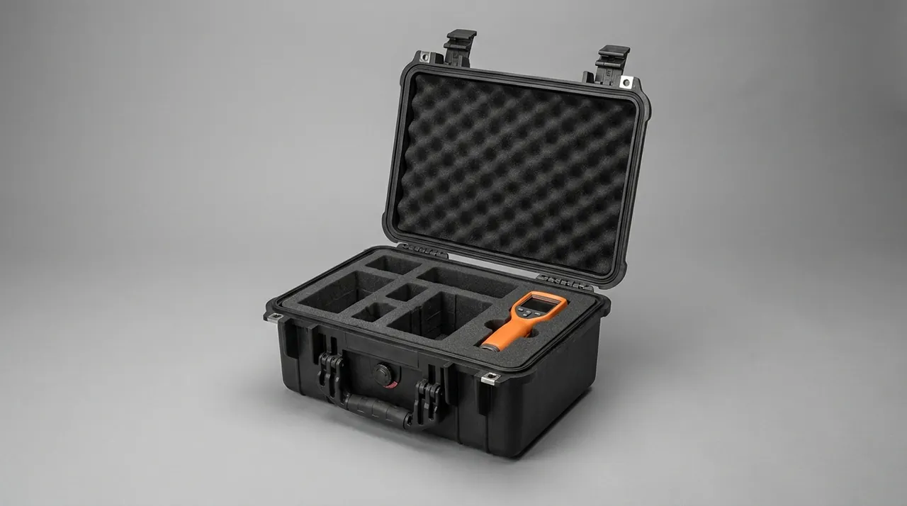
The recommended build is an annular liner combined with axial restraint blocks. The liner is bored to the roller body size and covers only the first 60 mm at each end, clear of the working zone, finished in 2 mm closed-cell foam with a flexible cushion layer above it. The restraint blocks sit either side of the journals and limit axial travel without loading the face.
Stacking must be calculated too. Case compression depends on the number of tiers and the effective load area, and roller loads must travel through the liner directly to the case floor. No roller body should ever carry a load from above. Marking the tier limit and gross weight on the case is mandatory; the calculation behind it is covered in stacking load testing for cases.
Paper Path Cleaning and Adhesive Residue Removal on Arrival
The first action on arrival is not installation but cleaning. This rule matters more for a folder than for most machines, because contamination from transport does not arrive inside the case. It arrives in the hours between opening and assembly: paper dust in the plant air, grease from the mechanic's gloves, moisture carried in on a tray from the floor. All of it settles onto a bare roller face while it waits to be fitted.
Cleaning is done by part, never with one brush for everything. On the roller face, sweep loose powder away with a soft bristle brush in one direction, wipe with the dedicated cleaner, then polish with clean nonwoven cloth; a metal scraper is forbidden and a compressed air blast is forbidden because it drives dust into the micro pores. On the upper knife arm slide, open the dust cover, wipe the race, dry it and refit the cover, because adhesive left in the race produces a cyclic stall on every stroke. On guides and bearing housings, check that the lip seals are intact, since an aged lip lets grease escape and then collects paper dust into a sludge. On the knife shaft and carriers, wipe the supporting journals, confirm there is no rust, and dress any knock marks on the carrier flange.
Acceptance of adhesive removal is simple: no visible residue, no gritty feel, no noise on rotation. The first two are easy. The third needs the paper path turned by hand through a full revolution, and any hesitation or concentrated friction at one angular position means residue or foreign matter is still present. After cleaning, run the moving parts once at low speed: bring the folder to minimum speed and pass twenty to thirty waste sheets, watching whether the register unit hunts and whether knife pressure stays stable.
Register Verification Before and After Packing
Folding accuracy is the final criterion, and it is measured in millimetres, but it cannot be measured inside a packed case. Verification therefore runs twice, once before packing and once after arrival, forming a chain that can be compared.
Before packing, while the machine is still in the workshop: check roller face roundness with dial indicator readings at the centre of the face and at both ends, normally within 0.05 mm, since anything larger means a deformed core or a delaminated cover. Record cover hardness at three points, because the absolute number means little on its own yet it is the only baseline for judging whether ageing continued. Establish a knife edge baseline by photographing the edge with a 10x loupe or bench microscope under side lighting, so the same shot can be repeated on arrival and chipping quantified. Preassemble the knife shaft with its bearings and measure runout once. Finally produce a register baseline by folding one signature of standard cross registration test sheets and measuring deviation with a cross rule and a straight edge. That millimetre figure is the only reference that can prove whether transport has disturbed the accuracy.
After arrival, once unpacked, installed and left to stand: remeasure roller face radial runout and Shore hardness and compare with the pre-packing data, treating any difference beyond the limit as transit damage. Remeasure knife shaft runout and check whether it has changed because bearings were lost or shims were refitted wrongly. Fold a baseline signature of the same specification at low speed and measure registration deviation exactly as before. The increment should stay within 0.3 mm; beyond that the shaft or the guides have moved geometrically and must be realigned. Run three signatures of live stock and watch whether deviation is stable, because a deviation that drifts with reel position points to web tension control rather than part accuracy. The value of this procedure is that it turns responsibility for transit damage from an argument into a comparison of numbers.
Cycle Time and Spare Part Management for Continuous Running
Folding rollers and knives are consumables on a high speed folder, replaced on a fixed cycle. A case therefore cannot be designed only for a one-off relocation; it has to survive repeated rotation.
Cycle time determines which case type makes sense. A high volume commercial printer changes knives two or three times a month and rollers every six weeks or so, which means the parts are almost always in transit. Such customers need reusable engineering cases: the shell is kept and the liner sets are replenished per cycle. JUNZHIJIA supplies liner sets for the three consumable families, so the customer replaces the liner and recovers full protection without replacing the shell. A small printer may run the same knife for six months, yet the removed roll has to sit in the workshop for a comparable period, and that scenario is about long term storage: the case needs a humidity indicator card, a generous desiccant charge and a shell in a UV and ozone resistant non-metallic material.
Either way a spare part list belongs in the case documents:
| Consumable family | Typical spares | Suggested stock | Storage requirement |
|---|---|---|---|
| --- | --- | --- | --- |
| Cutting | Circular knives, pressure pads, shaft bearings, shim sets | 3 knife sets, 2 bearing sets | One per cell, sealed inhibiting bags |
| Folding | Polyurethane rolls, rubber rolls, counter rolls | 1 to 2 per type | Annular liner, never stacked |
| Paper path | Dust covers, wipers, correction belts, guide shims | 2 sets each | Clean then sealed, kept apart from knives |
| Sealing | Dust lip seals, shaft seals | 3 each | Dry, dark storage |
| Fasteners | Carrier bolts, end nuts, balance weights | 2 sets each | Anti-rust oil, own compartment |
One point deserves emphasis. Counter rolls must be stored apart from glue rolls, because counter roll surfaces are hard coated or stainless and stacking them with a polyurethane roll produces both a dent in the cover and a scratch in the coating. Likewise thin aluminium guide shims must never sit above a knife. The choice between liner families is compared in custom foam inserts and pre-cut foam.
Frequently Asked Questions FAQ
Q: After a folder is stripped, how long may a glue roll lie outside the machine before it is fitted back?
A: A polyurethane cover should be fitted back within seven days at normal temperature and humidity. Beyond seven days the face starts collecting workshop dust, and a fingertip drawn across it feels gritty, which is where ageing begins. If assembly has to be delayed because of scheduling or floor space, fit a breathable dust cover rather than sealing it airtight, because a fully sealed cover traps vapour and any condensation inside it subjects the cover to a wet and dry cycle that is worse than no cover at all. Keep the roller away from direct air outlet, heater and sunlight, and never lay it directly on concrete or a metal tray, since floor moisture will wick upwards from the roller ends and enter the journal. Where several rollers share one crate, each needs its own liner so that a cover damaged in transit cannot be traced to the wrong roller, and the roller number should be written on the crate outside the sealed bag so the receiving store can match it to the machine. A cover that has already been creased once should not be returned to service even if the visible mark is faint.
Q: Can a circular knife be fitted straight from the case, or is there an inspection to run first?
A: It should never be fitted straight from the case. Three checks come first. First a visual and tactile inspection: move the view slowly along the edge under side lighting, looking for rust spots, white oxidation spots and micro chip notches, while sweeping a fingertip along the edge to detect any catch. Second, measure radial runout by mounting the knife on the shaft or a dedicated mandrel and taking dial indicator readings at three points around the edge, where the spread between readings should not exceed 0.03 mm; anything larger indicates taper or loss of roundness in the knife itself, and no amount of adjustment on the machine will correct it. Third, recheck the shaft: confirm all bearings are present, that the clearance group matches the fitting record, and that the journals are free of rust and knocks. Only after all three pass should the knife be fitted, and the first signature after fitting should be a waste run rather than live stock, because a knife reassembled with the wrong shim shows its error as an uneven cut edge rather than as a visible fault.
Q: Can register deviation caused by transport always be measured on arrival?
A: No, much of it is progressive. Light wear in a guide race and slight plastic set in the shaft shims may still sit inside tolerance during a static check on the day of arrival, then continue to accumulate over the first few hundred sheets until guide resistance rises and the infeed attitude drifts. That is why one extra verification is needed: fold a full signature of test sheets at low speed on arrival and measure registration deviation using the same method as before packing. If the increment exceeds 0.3 mm, a significant geometric change has occurred and the shaft and guides must be realigned rather than the machine simply put back into production. Repeat the measurement a second time after the machine has run for half an hour at working temperature, because thermal growth of the frame can itself shift register by a comparable amount and should not be mistaken for transport damage. Where the deviation is periodic rather than random, suspect the cutter or the fold roll; where it wanders with the reel, suspect web tension instead.
Q: Why does the paper path need its own compartment instead of travelling with the knives and bearings?
A: Mixing them creates two kinds of cross contamination. The first is dust: if guides, wipers and dust covers are not thoroughly cleaned before packing, residual paper powder and rubber powder lift into the air inside the case whenever it is vibrated and then settle on the blade edges and the bearing races. Paper powder at a Mohs hardness of 2.5 to 3 forms an abrasive three-body slurry that ploughs bearing races far more seriously than ordinary floating dust. The second is grease: guide lubricant can migrate inside a warm or sealed case and attach itself to the knife zone, causing paper debris to stick to the edge and altering friction. With a separate compartment the paper path becomes an independent cavity close to IP6X with its own desiccant and viewing window, which also lets the customer clean and assemble in the correct order. A viewing window matters more than it sounds: it lets the receiving store confirm that wipers and dust covers are present without breaking the seal that keeps plant dust out, and breaking that seal on arrival is the single most common way a carefully packed case is compromised before the machine is ever started.
Q: Can the liner for one folding roller be rotated between different rollers?
A: It is not advisable. Long contact with a roller face leaves a compressed glossy skin on the closed-cell foam, and that skin records the profile of the roller it was pressed against. If the liner is then moved onto a roller of a different diameter or hardness, the recorded profile no longer matches, and the face and liner end up touching at a point or across a gap, producing reciprocating squeeze under vibration. That squeeze leaves no visible damage at first but generates new shallow dents and accelerates ageing. The correct practice is to pair each liner with its roller and mark the liner with the matching number; replacing the roller means replacing the liner. An old liner can still serve as filler in a non-load-bearing position but must never again carry a roller face. Liner life is short in practice, typically three to six months of shop use, so replacement should be planned into the spare part list rather than treated as a repair. Foam that has been compressed and released many times loses resilience, and a liner that no longer returns to its original thickness eventually leaves a gap that lets the face drift under vibration.
Q: Must the humidity indicator card be read before the case is opened, or can it wait until installation is finished?
A: Reading it before opening is strongly preferred. The value of the card is that it shows whether contamination happened in transit or before packing, and that judgement has to be made while the case is still sealed. The correct sequence is: read and photograph the card, open the case, remove the desiccant, then clean and assemble. If the card has reached the high humidity range while the shell shows no damage and no water marks, the cause is insufficient desiccant or a sealing mismatch, which is a case design problem. If the card shows extreme humidity with droplets inside, the load may have shared a container with other cargo or been through extreme weather, and the specific leg should be traced. Skipping the first step destroys the most direct piece of evidence available later. Two cards are better than one: a second card placed inside the spare parts bag allows the receiver to confirm that the condition has not changed after the case has been opened and the machine reassembled, which separates a slow leak from a one-off ingress. Cards that show a reading should be photographed with the case number in frame, so that the record ties the environmental history to a specific machine rather than to a vague shipment.
Q: When VCI vapour corrosion inhibiting material is used for the knives, is desiccant still required?
A: Yes, because the two work by completely different mechanisms and both are needed. VCI suppresses the electrochemical reaction by letting inhibitor molecules migrate in the vapour phase and form a protective film on the metal, while desiccant physically adsorbs moisture and lowers the relative humidity, removing the water condition that corrosion needs. A damp high-salt atmosphere accelerates hydrolysis of the inhibitor and exhausts it faster, so holding the humidity down inside the effective window keeps the VCI working. Two practical rules follow. Bags containing VCI must be kept separate from the desiccant, because a desiccant that has absorbed moisture raises humidity right where it shortens the life of the inhibitor. And the bag must be sealed properly, because the concentration gradient that makes VCI work is maintained by the sealed volume; once the bag is breached the inhibitor is essentially exhausted within a few hours. Where knives stay in the case for more than a month, add a second indicator card inside a spare bag so the trend, not just the end point, can be read.
Q: How many tiers can the case be stacked, and can the knife cells and roller parts take the load?
A: Tier count must be calculated rather than assumed. Three inputs are needed: the allowable compression of the shell under load, which for foam or plastic cases is normally set as a static deformation limit around five percent for polypropylene; the total internal load, which is significant because circular knives weigh 5 to 15 kg each; and the overall height corresponding to the number of tiers, keeping the stack within about 2 m so that forklift handling and manual racking remain possible. The decisive issue is the load path. Knives must be carried by rigid case cells and must never let foam at the blade edge carry a stacking load. Roller assemblies must transfer their weight through the journals and the annular liner to the case floor with the body hanging clear. Any stacking arrangement that cannot guarantee the load bypasses the blade edges and the roller faces must be replaced by separate cases or additional rigid dividers.
Conclusion and Related Reading
Folding rollers and knives are consumables, not just components, so a good case is judged by dents on the face and chips on the edge rather than by shell thickness. JUNZHIJIA builds liners around each failure mechanism, supports mould development, OEM and ODM, and supplies case documentation, with manufacturing by Kexin New Materials (Guangdong) Co., Ltd.
Related Reading