

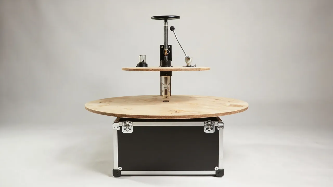
The first specification for a plywood press case is not load capacity but whether the platen is still flat on arrival. A press platen can weigh several tonnes and measure more than 2.5 m by 5 m, and the flatness of its working face together with the parallelism of the upper and lower platens sets panel thickness tolerance and surface quality. Components of this class are large and compliant: absolute strength is high, but bending stiffness is limited. Lose a support point in transit, or space supports too widely, and self-weight plus vibration produces elastic deflection. Even without permanent plastic deformation, released residual stress can bring the platen out of flatness again after installation. The same shipment usually also contains hydraulic cylinders, valve blocks, accumulators and servo valves, which fear contamination, corrosion and impact on mounting faces. A plywood equipment case therefore has to run two lines of protection at once: deformation control and contamination control.
This article is written for maintenance and upgrade teams at panel plants, press manufacturers and spare parts traders. It works through platen support and restraint, hydraulic component cleanliness, load calculations and lifting for heavy cases, long ocean-freight protection, test criteria and on-site handover, and closes with a selection matrix, FAQs and further reading.
Contents
- Why platen flatness matters more than strength
- Failure spectrum and load characteristics
- Platen cases: support and restraint design
- Hydraulic components: cylinders, valve blocks and accumulators
- Load calculation and lifting for heavy cases
- Temperature, humidity and long ocean voyages
- Choosing vibration isolation and cushioning values
- Test programme and acceptance criteria
- Unpacking on site and lifting handover
- Shipping spares and aftermarket parts
- Selection matrix and cost structure
- Customisation workflow and supply models
- Frequently Asked Questions
- Conclusion and related reading
Why platen flatness matters more than strength
Panel plants accept a press platen almost entirely on flatness and parallelism, and these are exactly the properties most easily damaged in transport, usually in a hidden way. In service, a platen is loaded at multiple points: force passes through the columns, bolster plates or cylinders and is distributed relatively evenly, so the platen itself sits in near-uniform compression. In transit the same platen usually rests on two or three supports, so self-weight generates a continuous bending moment, stress concentrations form near the supports, and the mid-span sags. With badly spaced supports the transit bending moment can far exceed the in-service value.
The more troublesome effect is the false reassurance of elastic recovery. Some platens look perfect after delivery and measure within tolerance, then show out-of-flatness only after installation, heating and pressing, when thermal expansion and residual stress release combine. Platen transport design therefore cannot stop at asking whether anything was struck; it must answer three questions. Where are the supports? How far apart are they? Can a support move under vibration?
The engineering approach reduces to one sentence: make the transit load case resemble the service load case. That means multiple supports, symmetrical arrangement and, where possible, continuous or near-continuous support, adding rigid support beams where point support must be converted into line or surface support. Case weight and packaging cost rise, but for a platen costing tens of thousands, this is the best value in the whole scheme.
Failure spectrum and load characteristics
Build a failure spectrum and load table before designing the case. Press-related shipment items fall into four groups, large bodies, hydraulic systems, heating and temperature control, and drive and control elements, and their failure logic differs sharply.
| Component | Main failure mode | Load characteristic | Protection focus |
|---|---|---|---|
| --- | --- | --- | --- |
| Press platen | Deflection, flatness and parallelism drift, face and port damage | Uniform self-weight plus vibration moment | Multi-point support, rigid beams, working face up |
| Cylinder and plunger | Bore scoring, bent rod, seal damage | Slender self-weight, axial impact | Axial support, rod guard, port plugs |
| Valve block and manifold | Mounting face impact, passage contamination, port seal damage | Local concentrated impact | One cavity per piece, port plugs, clean packing |
| Accumulator | Impact on pressurised vessel, fitting damage | Pressure vessel, sensitive to side impact | Upright fixing, fitting guards, anti-tip |
| Servo and proportional valves | Precision surface contamination, spool sticking | Very low impact tolerance | Dedicated sealed cavity, clean packing, ESD control |
| Heating plate and heat-transfer tube | Port deformation, internal contamination | Long component bending | End guards, long cavity support |
| Hydraulic pump | Shaft corrosion, inlet contamination | Medium-heavy, fragile shaft | Shaft cap, port plugs |
| Position sensor and encoder | Bent rod, stretched cable | Very slender | Dedicated long cavity, cable securing |
Two constraints stand out. Support for the large bodies and cleanliness for the hydraulics. They do not conflict; a single packaging system can resolve both by splitting the case into zones, with large parts following a structural load path and hydraulic parts following a sealed, clean path, sharing the same shell, lifting points and marking system.
Servo and proportional valves deserve a separate note. Their fits are measured in microns, and any particulate contamination in transit can cause spool sticking. They rarely ship as liftable assemblies; instead they travel as separate small cases or factory-packed units alongside the main case. Reserve dedicated cavities for them and state clearly that packing must not be opened before installation, so nobody breaks the seal early during a visual count.
Platen cases: support and restraint design
Support comes first, restraint second, cushioning last. The order cannot be reversed: if support is inadequate, no amount of foam will stop self-weight deflection.
Support layout. Place supports on a three-point non-collinear pattern or a symmetrical multi-point pattern. For long platens, use two end support zones plus a middle zone. For large-format platens, use at least six support points or two longitudinal support beams. A practical rule is to keep support spacing within one third of the platen's short-side dimension while limiting mid-span deflection to no more than half the allowable value. Actual numbers must come from platen weight, section inertia and allowable deflection, not from a rule of thumb copied onto an order.
What support beams do. When supports must be simplified, for example when the site can only lift from two points with a forklift, install rigid support beams inside the case to convert point support into line support. Beams are typically rectangular hollow section, channel or laminated plywood, and their own deflection must be far smaller than the platen's allowable deflection, generally designed to no more than one fifth of it. Lay a continuous soft pad, such as 5 to 10 mm rubber sheet or high-density EVA, between beam and platen so load spreads evenly and metal never contacts metal directly.
Working face orientation. The precision working face should point upward or toward a non-contact side of the case, so handling tools, fork tines and the ground cannot contaminate or score it. Where structure forces it downward, add a protective layer between face and support beam and state this clearly in the marking. For platens with holes, pins or locating features, cut dedicated slots for the protrusions so they never become load paths.
Restraint. Supports handle vertical load; restraint handles horizontal movement. Horizontal displacement is small but enough to drag the platen across its support pads and abrade the working face. Use adjustable side stops lined with soft material, fixed to reinforced case sections with bolts or clips. The principle is to limit movement rather than clamp: clamping raises additional stress at the platen edge, whereas restraint is enough.
Cushioning. Cushioning absorbs road and handling impact, and it belongs under the support beams or between case and vehicle, not against the platen working face. For very heavy items, add damping pads under the case and anti-slip damping mats between case and vehicle floor, so impact energy is dissipated at case level and less reaches the platen.
Hydraulic components: cylinders, valve blocks and accumulators
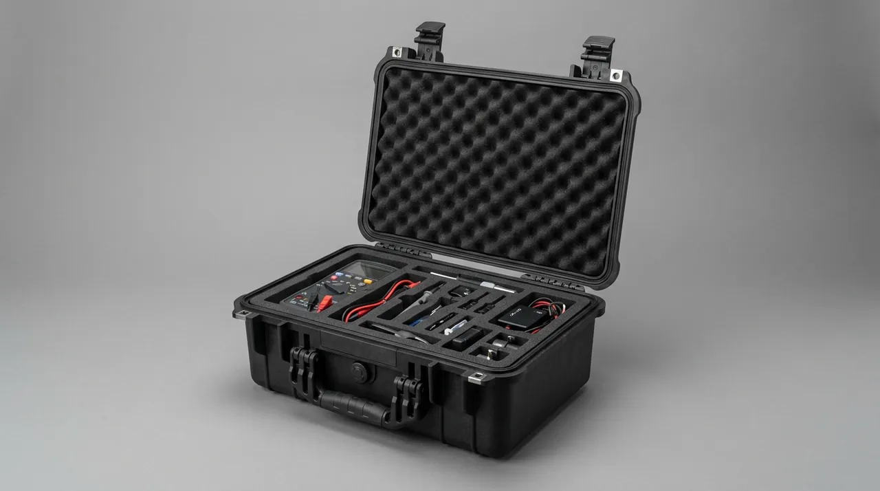
Hydraulic protection follows a completely different priority: clean, dry, undamaged.
Cylinders and plungers. A cylinder is a slender part, and the usual transit failures are a bent piston rod and a scored bore. Place it horizontally on multiple supports, at both ends of the barrel and at the middle, and never load through the piston rod. Fit a rigid or semi-rigid guard over the rod with a clean inner surface, and plug oil and bleed ports with caps or blind plates to keep foreign matter out. Where the customer insists on vertical transport, provide an upright bracket with anti-tip restraint and leave access at the barrel base so the rod does not carry the axial weight of the assembly for a long period.
Valve blocks and manifolds. Valve blocks are dense, high-value, high-precision items whose mounting faces and port seal faces are critical. Use one cavity per piece with a soft cavity floor, orient the mounting face upward or inward, cap every port and label the caps so nobody removes them during a count. Wrap each block in clean packing such as heat-shrink film or a clean bag and add desiccant to the cavity. For integrated manifold assemblies, build a dedicated carrier board with compartments so several blocks travel as one protected group.
Accumulators. An accumulator is a pressure vessel, and both its charge pressure and structural integrity need protection in transit. Fix it upright in the case on a grooved cradle that limits movement, control sway at the top with soft blocks, and fit guards over fittings so threads and seal faces are not struck. If the accumulator is charged, mark and secure it according to the applicable pressure vessel transport rules and avoid tilting or side impact. Requirements for packaging and securing pressurised components are described in our notes on pressure vessel component transport.
Pumps and motors. The shaft extension is the vulnerable point and needs a cap; inlet and outlet ports need plugs; support the housing on simple cradles so load lands on the casing rather than the shaft. Where a pump has an adjustment handle or sensor, provide local clearance so it is not loaded.
Pipes and hoses. Cap both ends of rigid pipe and secure it at its original bend radius without forcing it straight. Coil hoses and secure them so they are not compressed long-term or abraded against hard surfaces. Bundle tube assemblies into a long cavity with end guards.
The overall packing logic for hydraulics is: clean and plug at component level, isolate at cavity level, then seal and dehumidify at case level. All three layers are needed. Sealing the case without plugging components still leaves oil passages contaminated. Installation and handling practice for hydraulic assemblies is described in hydraulic lift component protection.
Load calculation and lifting for heavy cases
Press platen cases are often oversized and overweight, so design cannot rest on experience alone. It needs a load calculation.
Three calculation targets. First, the liner and support beams, checked for bending stress and deflection under platen weight with an impact factor. Second, the case base, checked for local bearing and overall bending under support reactions, especially during forklift handling where tines create concentrated loads. Third, the side walls and corner posts, checked for axial stability under stacking. Apply a dynamic amplification factor in transport, typically 1.5 to 2.0 depending on road conditions and restraint, rather than using static self-weight alone.
Forklift and lifting compatibility. A heavy case should have both fork pockets and lifting points. Fork pockets should run through the base, match local forklift tine dimensions, and be lined with wear plates. Lifting points should be four-corner ears or a lifting beam so sling forces are symmetrical. Keep sling angles moderate to avoid crushing the case walls, and use a spreader where necessary. For over-width cases, mark a lifting diagram and the centre of gravity on the side and supply lifting instructions with the case.
Moving and turning. If the case moves short distances inside a plant, castors and a towing point help, but castors are a classic weak point: under stacking they become load-bearing points and must be reinforced or made removable. Selection guidance for castors and telescopic handles is given in case castors and trolley handles.
Stacking limits. Heavy cases should be restricted to a single layer. If stacking is unavoidable, verify by stacking test and mark the permitted number of layers and the maximum load on the lid. For sea container transport, also check container floor capacity and eccentric loading limits, and prepare a load plan if needed.
Temperature, humidity and long ocean voyages
Platens and hydraulic parts differ in humidity sensitivity, but long sea voyages are hard on both.
Platens. A platen is usually steel or cast iron, and if its machined face is left unprotected, a humid sea voyage will produce rust spots. Light rust on a working face can be removed, but the removal process itself risks damaging flatness. Coat machined faces with rust-preventive oil or apply a protective film, and put desiccant and a humidity indicator card in the case. Where a platen has heating channels for thermal oil, drain and dry the channels before shipment and plug the ports so residual moisture does not rust the interior en route.
Hydraulics. Residual water or water-bearing oil inside a hydraulic cavity causes internal corrosion, and this is typically discovered only after commissioning, making it expensive to fix. Drain, dry and plug before shipment and keep the case interior at low humidity.
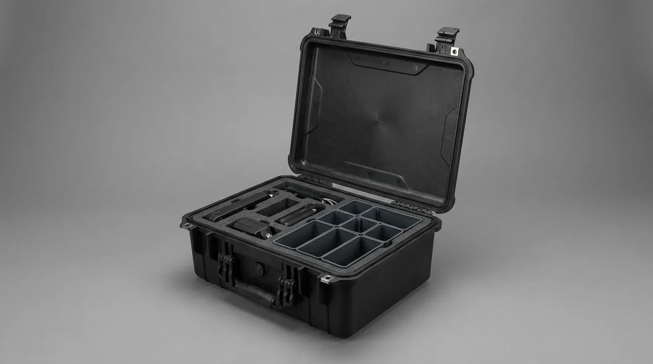
Managing internal humidity. Control relative humidity inside the case to 45 to 55 percent before closing, dose desiccant by net volume with at least 30 percent margin, and fit a hydrophobic breather vent to equalise pressure changes so the case does not develop negative pressure and draw moisture in. For voyages that may exceed 30 days, use a replaceable desiccant bay and a humidity recording label. Design considerations for cases facing severe temperature extremes are covered in case design for extreme temperatures.
Temperature cycling and condensation. A sea container experiences day-night and latitude-driven temperature swings, and condensate can form inside the case. Control measures include reducing free internal volume by filling voids with liner material, improving case sealing, and avoiding hygroscopic materials such as untreated paper or timber blocks inside the case. For high-value components, place a temperature and humidity recording label inside so the receiving team can judge whether further inspection is needed.
Choosing vibration isolation and cushioning values
Thicker cushioning is not better; values need a basis.
Step one: establish fragility and allowable acceleration. Fragility varies enormously. Servo valves and sensors tolerate very low acceleration, while a platen body tolerates higher acceleration but is far more sensitive to deflection. Group components and determine allowable acceleration and allowable deflection for each group.
Step two: estimate impact input. Handling drop height, forklift collision speed and road spectrum form the input. Practice is to assume drop heights by handling method and habit, for example 0.3 to 0.5 m for manual handling and 0.15 to 0.3 m for forklift work, then apply a safety factor.
Step three: read cushioning curves. Cushion performance depends on static stress, so read the material cushioning curve against load per unit area to determine thickness and density rather than choosing by experience. For very heavy items, combine a cushion pad with a vibration-isolating mount: the pad absorbs high-frequency impact while the mount isolates low-frequency vibration. Where a component is extremely impact-sensitive, design the cushion as a replaceable module so it can be renewed after a severe event.
Step four: verify. Confirm the cushion scheme by drop or impact testing. For high-value items that cannot be tested repeatedly, screen with an equivalent mass dummy first, then pack the real component once the scheme is proven.
A common error is to place cushioning directly between the platen working face and the support beam. Cushioning belongs outside the support system, for example between support beam and case base, or between case and vehicle. Between the working face and the support pad, use only a thin soft pad to spread contact stress, not to absorb impact.
Test programme and acceptance criteria
Validation for press component cases covers three families of condition: structural, environmental and dynamic.
| Category | Test item | Purpose | Main criterion |
|---|---|---|---|
| --- | --- | --- | --- |
| Structural | Stacking | Confirm case and liner do not deform under long static load | Deflection within agreed range, no liner shift |
| Structural | Lifting and forklift | Confirm lifting points and fork pockets carry load | No permanent deformation or cracking |
| Dynamic | Random vibration | Confirm supports do not shift and parts do not abrade | Displacement under 2 mm, no line scratches on faces |
| Dynamic | Drop or incline impact | Confirm cushioning and corner strength | Allowable acceleration not exceeded, no breakage |
| Environmental | Temperature and humidity cycling | Confirm corrosion and condensation control | No rust, no condensate, indicator unchanged |
| Environmental | Spray or rain test as required | Confirm seal integrity | No water ingress traces |
Criteria must be measurable. For a platen, use the measured flatness difference before and after transport as the core criterion, and require one measurement before loading and one after unloading, recorded in the same inspection file. For hydraulic parts, use absence of impact damage, absence of corrosion and intact packing on fits and ports as the core criteria.
For test references, domestic transport can follow the GB/T 4857 series, cross-border orders can use a distribution cycle approach, and whole-case performance verification can follow recognised industry programmes. Agree test items, sequence, sample size and failure disposition in the technical annex in advance.
Unpacking on site and lifting handover
The last mile of transport is the on-site handover, and it is where incidents concentrate.
Inspection before opening. On unloading, first check external case condition, including damage, moisture marks and seal integrity, then read the humidity indicator and shock indicators before deciding whether to open. If an indicator shows an out-of-limit event, record and photograph it first, then inspect internals according to the agreed procedure.
Opening. Heavy cases should be opened with suitable lifting equipment, not by hand, to avoid injury or a dropped component. Recommended sequence is lid, side panels, liner fasteners and support beams, releasing restraint layer by layer so a sudden release cannot shift the component. Inspect working faces and fit surfaces visually and dimensionally immediately after opening and retain photographic records.
Lifting handover. Lift a platen with rigging matched to its weight, using its own lifting holes or ears; never use support beams as lifting points. Keep the platen level during the lift so it is not loaded unevenly. Include lifting method, rigging specification and operator confirmation in the handover sheet to close the responsibility loop.
Final check before installation. Measure platen flatness again before installation and compare with pre-shipment data; confirm on hydraulic parts that all plugs have been removed, ports are clean and seals are intact. This step catches transit damage before installation and prevents it being masked during commissioning.
Shipping spares and aftermarket parts
Aftermarket press spares have their own characteristics: small batches, mixed categories, urgent lead times, and often a narrow window that matches a production shutdown.
The value of rotation cases. For common spares such as valve blocks, seal kits, sensors and heating elements, build standardised rotation cases with fixed cavities and a numbering system. They reduce the risk of improvised packaging on site and speed up counting. Where spares travel repeatedly for repair, maintainability, including replaceable hardware and replaceable liner modules, matters more than anything else.
Urgent shipments. Urgent parts often move by air or dedicated truck, where handling differs from routine sea freight and impact can be higher. Design urgent shipments for a higher impact case and fit shock indicators. For overweight urgent items, confirm the destination's lifting capability in advance so the case can actually be unloaded on arrival.
Accessory spares and special tools. When a machine ships with accessory spares and special tools, they are usually small, numerous and easily mixed up. Pack them as one set per case with compartmentalised location, list every item on the packing list, and print item numbers on the liner for easy on-site checking. Give special tools their own cavity with corrosion protection so they do not rust during long storage.
Long-term stored spares. Where spares sit in a warehouse for months, the case needs a stackable structure and humidity monitoring, plus a periodic inspection routine, ideally checking desiccant and metal surfaces every six months. Hydraulic spares in long storage need particular attention to seal ageing, so control temperature and humidity to the manufacturer's recommended storage conditions.
Selection matrix and cost structure
Case selection is driven by four variables: component weight and size, transport mode and distance, number of trips, and site handling conditions. The table below recommends a configuration for each common combination.
| Scenario | Component profile | Recommended case | Liner and support | Cost focus |
|---|---|---|---|---|
| --- | --- | --- | --- | --- |
| New machine platen, domestic road | Oversize, overweight, one-way | Thick-wall plywood case, beams, corner protectors | Multi-point pads plus side stops | Structural material and lifting parts |
| Imported platen replacement, sea freight | Oversize, overweight, long cycle | Framed timber case, sealed liner layer, vent valve | Continuous beams, rust film, desiccant | Corrosion and dehumidification |
| Valve and servo valve spares, batch | Small, high value, repeated trips | Rotomoulded or aluminium frame case, replaceable hardware | Die-cut cavity array plus sealed packing | Liner process and clean packing |
| Cylinders and accumulators | Slender and pressure vessel | Long-cavity timber or steel frame case, upright cradles | Multi-point support, guards, port plugs | Guards and restraint structure |
| In-plant transfer | Medium weight, short distance | Rotomoulded case with castors and handle | Modular assembled liner | Hardware and mobility mechanism |
Cost distribution is commonly 35 to 50 percent for case structure, 25 to 40 percent for liner and support, 8 to 15 percent for sealing and dehumidification, and 5 to 10 percent for hardware and marking. The liner and support share is the most likely to be redesigned repeatedly if the brief is unclear, so confirm the component list, support positions and lifting method at design stage rather than after production starts.
Tooling investment and amortisation are covered in custom case mould investment and amortisation. For single oversize items, tooling is often unnecessary; CNC machining plus structural assemblies meet the requirement at lower setup cost.
Customisation workflow and supply models
Press component case customisation should follow five gates, each with defined deliverables.
- Technical input confirmation: component drawings and measured dimensions, weight and centre of gravity, working and fit surface locations, transport mode and route, handling equipment available, number of trips;
- Design and calculation: support layout with deflection check, case structure selection with load calculation, liner and cushioning scheme, sealing and dehumidification, with drawings and calculation notes;
- First article and validation: build the first case, run packing, lifting and opening drills with the real component or an equivalent dummy mass, and screen by drop test where needed;
- Scheme confirmation and pilot run: freeze process parameters after fit and work path are confirmed;
- Series production and dispatch checks: work to the agreed sampling plan and release the packing list together with the inspection records.
One requirement is specific to oversize items: a lifting drill. Many problems, including unsuitable lifting points, excessive sling angles and an offset centre of gravity, only appear when the load actually leaves the ground. Complete a full lifting drill at first-article stage, record rigging specification, lifting points and crew size, and deliver lifting instructions with the case.
Routine plywood-press case sizes ship from standing stock, while oversize platens and press-specific bodies are fabricated to the buyer's drawing. Press line builders can have the whole packing scope timed to their assembly takt, with process documents and on-site support included.
All case bodies are produced and delivered by Kexin New Materials (Guangdong) Co., Ltd., whose business covers wholesale supply, agency distribution, OEM and ODM manufacturing and global delivery; for heavy plywood press components, the two parties can agree contract terms governing third-party testing and material documentation, including material composition, load calculation notes and test reports to the agreed standard.
Frequently Asked Questions
Q: The platen is extremely heavy; will adding layers of foam solve the deflection problem? A: This is the most common misconception. Foam absorbs impact energy but cannot resist self-weight deflection, because deflection comes from the bending moment between supports and foam provides no support reaction. Placing a platen on soft foam actually softens the support and can increase mid-span sag. The correct route is support geometry: add support points, reduce spacing, and install rigid support beams between points so the platen's load case approaches its service condition. Foam or rubber pads belong under the support beams or between case and vehicle, where they absorb handling and road impact, not between the working face and the support points. Between the working face and the support beam, a 5 to 10 mm soft pad is enough to spread contact stress and prevent scoring. Judge the scheme by the measured flatness difference before and after transport, not by foam thickness. Quantify the target as well: on a long platen, support spacing should keep mid-span deflection within half the permitted value, and the support beams themselves should deflect no more than a fifth of that figure.
Q: What preparation do hydraulic components need before packing? A: At least four steps. First, drain: empty the working fluid from cylinders, pipes and valve cavities so it cannot leak into the liner or congeal at low temperature; heat-transfer oil channels need the same drain and dry treatment. Second, dry and preserve: after drying the interior, apply internal corrosion protection to the manufacturer's requirement and a thin preservative oil film on fits and mounting faces. Third, plug: cap all oil ports, bleed ports and openings with plugs or blind plates, both to keep foreign matter out and to prevent oil vapour escaping. Fourth, clean packing: for valve blocks and servo valves, wrap in clean material before locating in the cavity so nobody opens the seal early during a count. Note that these are component-level actions and cannot be replaced by sealing the case. Sealing alone, without component-level plugging and drying, still produces internal corrosion and passage contamination after a long voyage, discovered only at commissioning.
Q: How do we determine lifting points and fork pocket positions on an overweight case? A: The key is to match the reaction distribution to what the case structure can carry. For lifting, distribute points evenly at the four corners or on a dedicated lifting beam so sling forces are symmetrical. Where mass is clearly offset, for example a platen to one side and hydraulic parts to the other, the centre of gravity marking must be accurate or the case will tilt and swing during the lift. Fork pockets should run through the base, match local forklift tine dimensions, be lined with wear plates, and be positioned so the tine centreline aligns with the case centre of gravity to prevent forward tipping. At design stage, treat lifting and fork points as concentrated load cases and check local strength of base and corner posts with a dynamic amplification factor of 1.5 to 2.0. At first-article stage, strongly consider a full lifting drill, recording rigging specification, lifting points and working method, and deliver lifting instructions with the case. This catches most lifting problems before delivery.
Q: For long sea voyages, should platen and hydraulic parts be protected differently? A: Yes. A platen's working face is a machined plane, and the objective is to avoid rust spots without a de-rusting process that could disturb flatness. Coat machined faces with rust-preventive oil or apply a protective film, and remember that a platen with heating channels must be drained and dried with ports plugged to prevent internal corrosion. Hydraulic parts need both internal cavities and exposed fits free of corrosion, with oil passages uncontaminated, so the emphasis is on draining, drying, plugging and clean packing, plus low internal humidity. The two can share one case-level sealing and dehumidification system, but component-level treatment must be executed separately. For humidity management, control the case interior to 45 to 55 percent before closing, dose desiccant by net volume with 30 percent margin, and fit a hydrophobic breather vent to equalise pressure. For voyages over 30 days, switch to a replaceable desiccant bay with a humidity recording label, and decide from the indicator whether further inspection is needed on arrival.
Q: Should the case base be fitted with castors? A: It depends on the use case, but understand the structural cost. Castors make short in-plant moves and turns easy and add real value for frequently repositioned rotation cases. Under stacking and long-haul transport, however, they become load-bearing points, concentrating load on a few mounts and risking cracked mounts or local base deformation. If castors are required, take three measures. Reinforce the mount area with a thicker base plate or steel insert. Make castors removable so they can be taken off and packed separately before shipment, letting the case bear load through a flat face. State stacking limits explicitly, and normally avoid multi-layer stacking for castor-equipped cases. Where forklift handling is also needed, fork pockets and castors must not interfere and pocket height must match tine dimensions. An alternative is a skid or pallet base so a forklift handles all movement instead of manual pushing. Where castors stay fitted for transport, specify locking brakes and record the wheel load rating, so nobody overloads one mount by pushing a loaded case up a ramp.
Q: How do we tell whether a platen was distorted in transit after unpacking on site? A: Use two measurements and one comparison. Measure and record platen flatness before loading, including relative heights at key points where practical. On arrival, do a visual check before removing packaging restraint, then take a second flatness measurement after restraint is removed and the platen is placed on the specified supports, and compare with both the pre-shipment and factory values. The criterion is normally that the difference across transport stays within an agreed limit rather than the absolute value alone, because the absolute figure can be affected by the temporary support method on site. Keep the measurement datum and placement method identical or the data is not comparable. Also inspect for scratches, rust spots and port damage on the working face and for structural impact on the body. File the results and photographs with the handover sheet, so a later flatness dispute can be traced to pre-transport, pre-installation and post-installation states. Agree the measurement points and the datum before shipment, because a reading taken from a different set of points is not comparable.
Q: Spares come in small batches and mixed categories; how do we make packaging economical? A: Standardise rotation and compartmentalise by category rather than designing new packaging for every batch. Group spares by category, such as valve blocks, seals, sensors, heating elements and fasteners, and define one standard cavity size and fixing method per category to create combinable modules. Then assemble a case from the modules the order needs. This avoids redesign each time and lets parts be returned to their places quickly. High-value precision parts still need individual packing inside their cavities, while low-value general parts can use compartment trays with clear marking. The rotation case itself should be maintainable, with replaceable hardware, individually replaceable liner modules and corner bumpers. For long-stored spares, add humidity monitoring and a periodic inspection routine. For urgent shipments, design for higher impact, fit shock indicators, and confirm destination lifting capability in advance. Keep each module within a sensible manual handling weight so one case does not need a crane, and label every module with its category and cavity layout so a mixed order can be assembled without opening the liner. Maintain a master list of module definitions under revision control.
Q: Should accessory packaging cases match the machine assembly takt? A: Matching them significantly reduces on-site confusion and damage. A common problem at machine builders is that packaging runs out of step with the assembly line, so components coming off the line have nowhere to wait and get stacked temporarily, or cases arrive too early and block the aisle, or too late and leave parts exposed on the shop floor. Bring packaging delivery milestones into the production plan, specifying which components ship with the machine, which go in separate cases, and when each case must arrive. Accessory cases should also support taking parts in assembly order, meaning the next part needed sits in the most accessible position so nobody has to move a whole case to reach one item. Where a component needs a second move on site, from staging area to installation position, the case should be liftable or forklift-compatible to reduce bare handling. Packing lists, marking and unpacking instructions should also align with the assembly process documents so on-site teams can check and pick by drawing.
Conclusion and related reading
The challenge with press component cases is fitting two completely different protection targets into one packaging system. The large, heavy, deflection-sensitive platen needs multi-point support and a rigid load path, while the small, precise, contamination-sensitive hydraulic parts need clean packing and low humidity. The first is solved by structural calculation and lifting compatibility, the second by component-level preparation and dehumidification, and the two share one case shell, marking system and handover process. For buyers, the highest-value step is to hand over the component list, weights and centre of gravity, working surface locations, transport route and handling conditions at design stage, then complete support validation and a lifting drill at first-article stage.
Fixing methods for press and hydraulic components during in-plant transfer are covered further in hydraulic lift component protection and transport of large silo equipment components. Where components are impact-sensitive, our notes on shock-absorbing cushion liners explain how cushion layers and restraint structures work together. Panel plants that also handle kiln-dried material logistics may find the packaging logic in industrial kiln component cases useful for comparison.
Related reading