

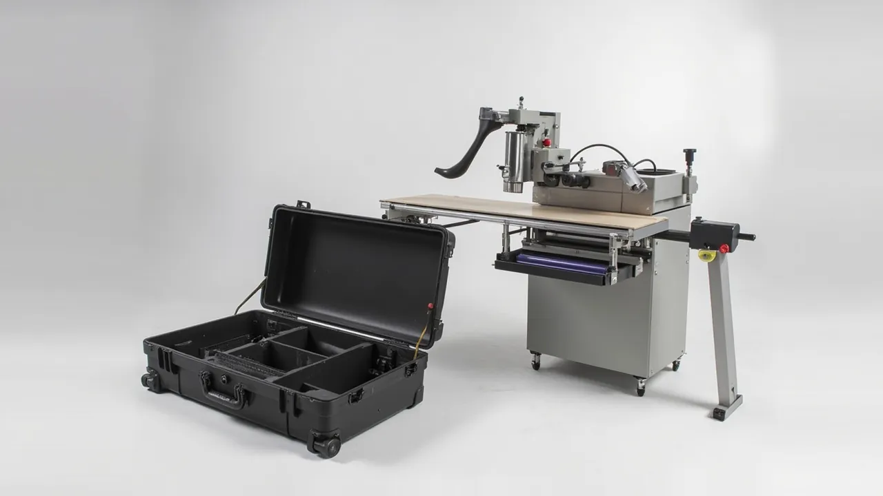
Edge banding components rarely fail by breaking; they fail by getting dirty first. The glue pot, glue roller, glue shaft, scraper and pressure roller form a channel that is extremely sensitive to cleanliness. Once the pattern on a glue roller is packed with cured adhesive, metal chips or dust, the adhesive lay-down is no longer uniform. Once a pressure roller face picks up a hard particle or takes an indentation, the banded edge shows marks, shiny spots or uneven squeeze-out. If terminals on heating elements and temperature control parts get damp or contaminated, contact resistance and local overheating follow. Panel furniture equipment components are not usually the most expensive items in a plant, but the downtime and re-setting cost of replacing them is high, so the design objective for an edge banding equipment case should be stated plainly as anti-contamination, anti-impact and moisture control together, rather than impact resistance alone.
This guide is written for maintenance departments in panel and custom furniture plants, edge banding supervisors and equipment distributors. It works through anti-contamination packing for glue system parts, face accuracy protection for pressure rollers, moisture control for heating and temperature control components, liner cleanliness grades, test and acceptance criteria, and the rotation and cleaning loop for spares, closing with a selection comparison, FAQs and further reading.
Contents
- Why the glue system fears contamination above all
- The failure spectrum of contamination and damage
- Contamination control for glue pots, rollers and shafts
- Pressure roller cases: face accuracy and runout protection
- Heating and temperature control components
- Liner cleanliness and material compatibility
- Sealing, desiccant and humidity indication
- Testing and acceptance: turning cleanliness into criteria
- Clean unpacking and pre-installation checks
- Rotation cases and the cleaning loop
- Selection comparison and cost structure
- Prototyping and supply models
- Frequently Asked Questions
- Conclusion and related reading
Why the glue system fears contamination above all
Start with how contamination actually happens. In edge banding, hot melt adhesive is heated in the glue pot and carried to the panel surface by the glue roller. The roller face usually carries a specific pattern or texture that controls adhesive distribution, and the depth of that texture is often only a few tenths of a millimetre. Once cured adhesive, carbonised material or metal chips lodge in the texture, the adhesive delivered in that zone drops, producing discontinuous or locally missing glue, which leads to poor bonding or later lifting of the band.
During shutdowns, repairs and equipment relocation, this contamination is often self-inflicted. Parts come off the machine and go straight into a case without cleaning, so residual adhesive cools, cures and combines with dust into hard particles that are difficult to remove. Or parts are set down on the shop floor and pick up grit and swarf. Or several components share one tote, and a roller end face strikes the patterned surface of the glue roller. On arrival everything may look fine until the machine is commissioned, when uneven glue lay-down appears and diagnosis takes hours or days.
The first principle for glue system protection is therefore to clean to an acceptable condition before packing; packaging is not a substitute for cleaning. The second is to separate components by cleanliness requirement into different zones or cases. The third is that packaging material cleanliness must match the component, because a shed-shedding, moisture-absorbing or plasticiser-bearing material simply creates a new contamination source inside the case.
The failure spectrum of contamination and damage
The table below groups common edge banding transport failures by component with their protection priorities, and can be used directly as a design input.
| Component | Contamination and damage mode | Sensitive face | Protection priority | Compartment advice |
|---|---|---|---|---|
| --- | --- | --- | --- | --- |
| Glue pot / melter | Carbonised residue, wall scoring, deformed heating face | Inner wall and heating contact face | Drain adhesive, clean packing, avoid compression | Dedicated cavity plus clean liner |
| Glue roller / applicator roller | Texture packed, face scoring, journal damage | Patterned working face | Float the pattern, fit guard, never stack | Individual suspended cavity |
| Glue shaft / coating shaft | Hard particles embedded, bent shaft | Shaft face and extension | Protective film on face, shaft guard | Long cavity plus end cradles |
| Scraper and trimming blade | Chipped edge, flatness drift | Cutting edge | Edge guard strip, separate cavity | Individual edge cavity |
| Pressure roller and wheel | Face indentation, runout deviation, rubber layer damage | Roller face including rubber | Float the face, axial end restraint | Split half-cradle |
| Heating tube and hot air unit | Damp terminals, bent tube body | Terminals and tube | Dry terminal packing, tube guards | Long cavity plus end guards |
| Thermostat and sensor | Terminal oxidation, bent probe | Terminals and probe | Moisture-proof packing, probe guard | Dedicated small cavity |
| Chain and timing belt | Stiff link, deformed belt body | Links and teeth | Coil and secure, release tension | Reel or long cavity |
| Pneumatic components | Scored piston rod, damaged ports | Rod and ports | Rod guard, port plugs | Dedicated cavity |
| Standard fasteners | Mixing, contamination | None | Compartment tray plus marking | Compartment tray |
Two lessons follow. Compartmentalisation is the first and most effective line of defence. Glue rollers and pressure rollers have completely different sensitive faces: one suffers when its texture is packed, the other when its face flatness or runout changes. In a shared cavity, any vibration can bring a hard roller end face into contact with glue roller texture, creating damage that is both hard to detect and hard to repair. Separate zones by sensitive-face type and put a solid wall between them.
The second is that the glue pot is frequently overlooked. It is a thin-wall vessel, and compression in transit deforms the inner wall, which directly affects melt flow and temperature uniformity. Give the pot its own cavity with adequate clearance from the liner wall, and support it on a flat base rather than at points so load is not concentrated.
Contamination control for glue pots, rollers and shafts
Glue system packing follows four steps: clean, wrap, locate, dehumidify.
Clean. After removal, drain the adhesive while it is still soft and remove residue with a dedicated cleaner or purging compound. Avoid metal scrapers, which damage plating or texture. Let the part cool to room temperature and wipe with a lint-free cloth. In the roller texture, use a soft brush with cleaner to lift adhesive out of the grooves and never a hard tool. Move to wrapping quickly after cleaning, because airborne wood dust and adhesive dust in the shop will reattach within a short time.
Wrap. Wrapping material must be three things: non-shedding, non-absorbing and free of substances that affect metal or the adhesive path. Clean PE film, rust-preventive film or dedicated clean bags all work. For glue rollers and shafts, apply a protective film over the patterned face before wrapping; the film itself must be clean material and ordinary tape should not be used, because residue transfers to the working face. Where rust protection is needed, vapour phase inhibitor film can be used, but confirm compatibility with the adhesive path materials.
Locate. The rule is that sensitive faces float and structure carries weight. Support a glue roller on its journals at both ends with 8 to 15 mm clearance between the pattern and the cavity wall, touching nothing above or below. If it must lie flat, use at least two soft support strips positioned away from the sensitive pattern. A glue shaft is slender and needs multiple supports at the journals and the middle, never a free mid-span that can bow.
Dehumidify. Residual moisture on glue system parts can produce rust spots after long storage, particularly at bearing seats and shaft extensions. Place desiccant in the cavity dosed by net volume and add a humidity indicator card for precision parts. Where the customer mostly uses solvent or water-based cleaners, note that cleaner residue is hygroscopic, so parts must be thoroughly dried before wrapping.
Packing sequence. Supply illustrated packing and unpacking instructions stating the pick order and prohibited actions, such as prying near a patterned face with a metal tool. For machines that require the glue pot to be fitted before the glue roller, align the packing order with the installation order so nobody has to disturb upper layers to reach a lower component.
Pressure roller cases: face accuracy and runout protection
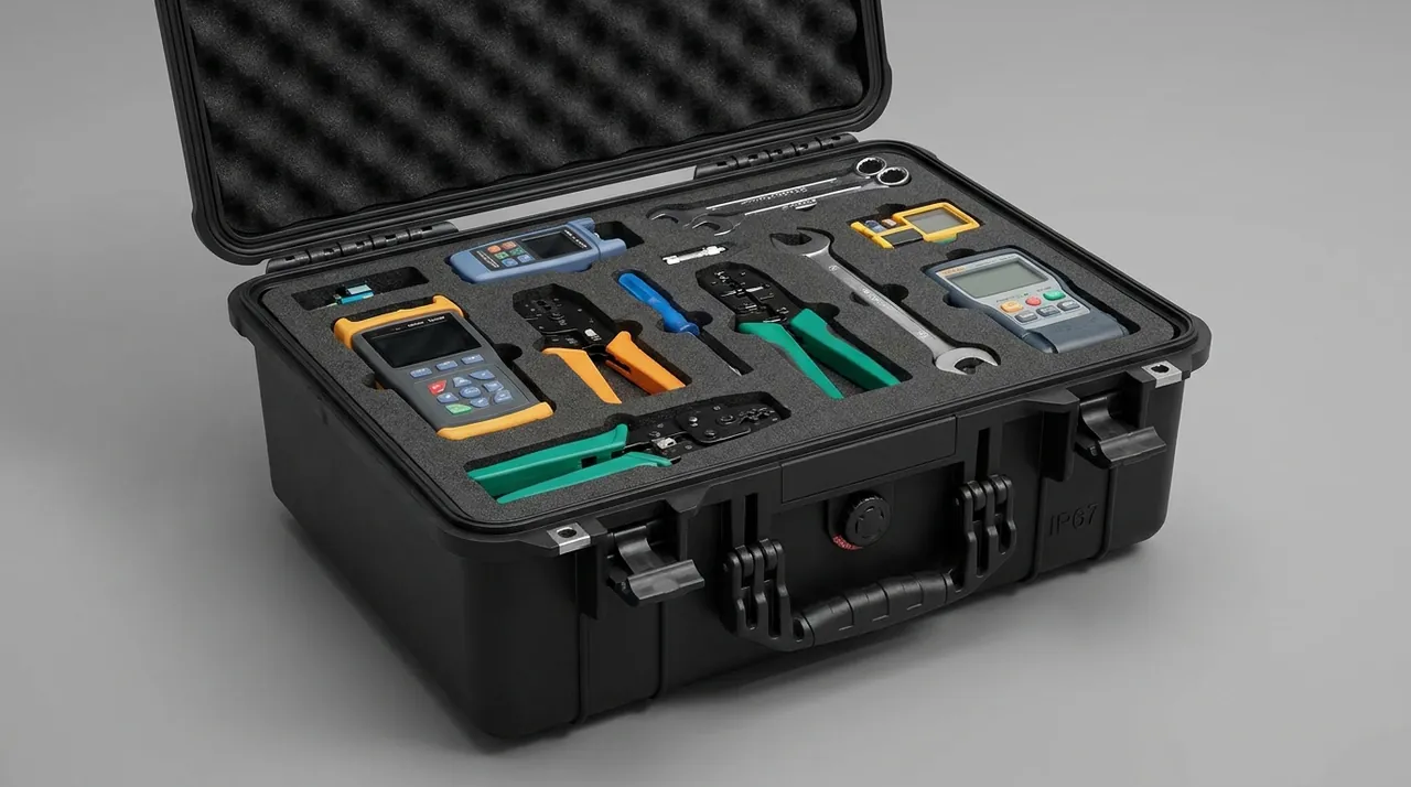
Pressure rollers press and form the band, and their face, especially the rubber layer on coated rollers, together with runout, determines adhesion quality and appearance. Three things matter: float the face, restrain axially, protect the rubber layer.
Float the face. The roller face is a functional surface and must have clearance to any hard surface. Use a split half-cradle: the lower half carries weight with a soft, radiused contact that produces line contact, while the upper half only limits runout and can be adjustable, lightly loaded for transport and released before installation. Position the contact away from critical working zones, such as the rubber section of a coated roller.
Restrain axially. If a roller can move freely along its axis, its end face will strike the cavity wall and deform, or the bearing seat will be damaged. Fit soft-lined stops at both ends, bolted to reinforced case sections. The stops should limit rather than clamp, so no additional stress is introduced into the roller body.
Protect the rubber layer. The coating on a coated roller is relatively soft and can be cut by sharp objects or take a permanent indentation under concentrated load. Beyond floating location, wrap the coating in a soft protective sleeve of clean PE foam or a dedicated guard whose inner surface is clean and plasticiser-free. For long transport periods, avoid a sleeve pressed tightly against the coating for months, which can cause adhesion; leave a small gap or use an anti-stick interlayer.
Treat roller types differently. Steel and coated rollers have different priorities: steel rollers suffer more from impact that ruins runout, coated rollers from indentation and cuts. Store them in separate cavities and print roller type and diameter on the cavity marking. For roller assemblies with bearing housings, keep bearing seats clean and corrosion-free and give the housing its own guard where useful.
Handling and lifting. Rollers are cylindrical and roll easily when carried by hand. Provide grip positions or lifting holes in the case and state clearly in the instructions that rolling a roller by hand is prohibited. For heavy rollers, provide lifting points and use soft slings rather than wire rope that can crush the face.
Heating and temperature control components
Edge banding heating and temperature control parts include heating tubes, hot air units, thermostats, thermocouples and sensors. They share three characteristics: they carry power, they fear moisture, and their terminals are fragile.
Heating tubes and hot air units. A heating tube is a slender metal tube that bends easily in transit, and its terminals can develop increased contact resistance and local overheating if they get damp or dirty. Place the tube body in a long cavity with guards at both ends, wrap the terminal area in moisture-proof material inside a clean bag, and add desiccant. Where a tube has lead wires, coil and secure them so they cannot be pulled or stretched.
Thermostats and sensors. A thermostat is an electronic component, so it needs protection from static as well as moisture and vibration. Use a dedicated cavity lined with antistatic or at least non-charge-accumulating material. For thermocouples or probes, guard the probe so it cannot bend or be struck, both of which shift measurement accuracy. For thermostats with a display, add a soft protective layer so the screen is not compressed.
Heating plates and hot press modules. Where an edge banding machine includes heated platen components, deflection control follows the same logic as rollers: multi-point support to prevent long-term self-weight sag, plus rust protection on working faces during transport and storage. For parts with thermal oil or heating channels, drain and dry before shipment and plug the ports to prevent internal corrosion.
Electrical cabinet modules. When components ship as electrical modules such as terminal boards, inverters or servo drives, add insulation protection, antistatic packing and short-circuit prevention to the usual moisture and vibration requirements. Use an antistatic liner and add ESD and no-compression warnings to the case marking.
Liner cleanliness and material compatibility
Liner material carries more weight in this class of case than in most industrial applications, because it affects both impact protection and contamination control.
Cleanliness. Any liner material touching a sensitive face must be non-shedding, non-migrating and non-exuding. Options include closed-cell EVA at 45 to 70 kg/m³, cross-linked PE, polyurethane foam with attention to long-term compression set, and flocked or film-faced surfaces. Materials to avoid include open-cell sponge, cheap foam that powders, and soft PVC sheet that can migrate plasticiser.
Compatibility. Some materials release trace substances in a long closed environment, which can corrode metal or affect adhesive curing and bonding. For liner material contacting glue system parts, request compatibility or composition data from the supplier and, where needed, run a sample test: place the material against the sensitive face for a period, then check for colour change, adhesion or residue.
Surface treatment. Where the liner will be cleaned frequently, choose a dense, wipeable surface or face the liner with a replaceable clean film. For rotation cases used to send parts out for servicing, design a removable tray floor so chips and adhesive debris can be cleared quickly.
Process choice. Liner forming process selection follows the same logic as other equipment cases, with extra requirements here. After CNC machining, all swarf must be removed, particularly fine particles inside cavities. Die-cut edges must be burr-free and non-powdering. Thermoformed parts must be checked for mould release residue. These process details set the initial cleanliness of the case, so write a requirement that liner cavities show no visible debris or powdering into the acceptance conditions.
Sealing, desiccant and humidity indication
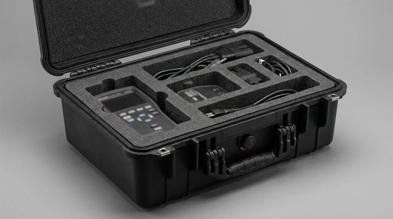
Moisture control is not optional here, because bearing seats, electrical terminals and steel parts in glue system components all suffer from damp conditions.
Sealing. Follow established IP practice with a foamed silicone or EPDM gasket and a double-lip case mouth to preserve sealing through repeated cycles. The gasket should be replaceable as a single cartridge for on-site maintenance. For cases that get washed, choose a gasket with lower compression set and increase the compression.
Pressure equalisation. A fully airtight case develops negative pressure under temperature cycling and draws moisture in, so fit a hydrophobic breather vent high on the case to equalise pressure without admitting liquid water. Keep the valve away from areas where water can pool on top and add a raised boss so the membrane cannot be torn.
Desiccant and indication. Dose desiccant by internal net volume with at least 30 percent margin, distributed where air can reach it. For precision or metal parts, add a humidity indicator card fixed where it is visible on first opening. For spares held in long storage, use a replaceable desiccant bay so maintenance does not require repeated opening of the main cavity.
Closing environment. Complete final closure in a dehumidified area at 45 to 55 percent RH. Closing a case in an 80 percent RH shop leaves high initial internal moisture and consumes desiccant quickly. Do not leave ordinary paper labels or cardboard inside, because paper-based materials absorb moisture and become an internal moisture source; use laminated synthetic labels or print directly on the liner.
Testing and acceptance: turning cleanliness into criteria
What distinguishes acceptance for this class of case is that cleanliness and surface condition must be converted into executable criteria.
| Acceptance category | Inspection item | Method | Example criterion |
|---|---|---|---|
| --- | --- | --- | --- |
| Cleanliness | Liner and cavity debris | Visual plus white cloth wipe | Cloth shows no visible particles or powdering |
| Cleanliness | Sensitive face contamination | Visual plus clean cloth wipe | No cured adhesive, metal chips or oil transfer |
| Structure | Cavity dimensions and interference | Calliper plus physical fit | Matches drawing, sensitive faces have clearance |
| Structure | Roller float and restraint | Feeler gauge plus push-pull check | No face contact, axial movement within limit |
| Sealing | Gasket contact and compression | Visual plus compression measurement | Continuous contact, compression within range |
| Environment | Internal humidity | Indicator card | Below the agreed threshold |
| Marking | Compartment and item numbers | Item-by-item check | Matches the packing list |
| Packing | Wrapping integrity | Visual | Clean bag intact, guards in place |
The recommended test set covers random vibration to verify that cavities do not shift and sensitive faces do not abrade, drop or incline impact to verify corners and cradles, stacking to verify lid and liner clearance, and temperature and humidity cycling to verify moisture protection. Criteria should be quantitative: no new indentations or scratches on roller faces, no material packed into glue roller texture, liner displacement under 2 mm, and no condensate inside.
Test references can follow the domestic transport packaging test series, while cross-border orders can use a distribution cycle approach. Agree test items, sequence, criteria and failure disposition in the technical annex in advance.
Clean unpacking and pre-installation checks
The sensitivity of edge banding components to contamination means the work between unpacking and installation must be disciplined.
Unpacking environment. Open cases in a relatively clean area, avoiding the vicinity of sawing or sanding stations. Where site conditions are limited, at least sweep the work area before opening so dust is not raised into the cavities.
Opening sequence. Release restraint layer by layer: outer seal, lid, liner fasteners, wrapping, then the component, so upper items never press on lower sensitive faces during removal. Check the humidity indicator and cushioning condition immediately and keep photographic records.
Pre-installation checklist. Include the following: glue roller texture free of packing; glue pot interior clean with no damage to the heating face; pressure roller face free of indentations and scratches with normal runout; heating tube terminals dry and tight; thermostat wiring complete; bearing seats free of rust; and all protective wrapping removed. The last item is the one most often missed, and a forgotten film layer causes glue faults.
Tracking leftover protective layers. Because glue system parts often carry several layers of protection, including film, sleeve and clean bag, leaving one layer on is not unusual. Print the number of protective layers on the cavity or list the layers and removal requirements item by item on the packing list, turning the check into a countable step.
Handling anomalies. If contamination or damage is found on a sensitive face, follow the agreed procedure: record, photograph, assess whether cleaning or replacement is required, and never install a component with a hidden defect and rework later. Agree an inspection window in the contract, for example within 24 hours of unloading, so responsibility can be established.
Rotation cases and the cleaning loop
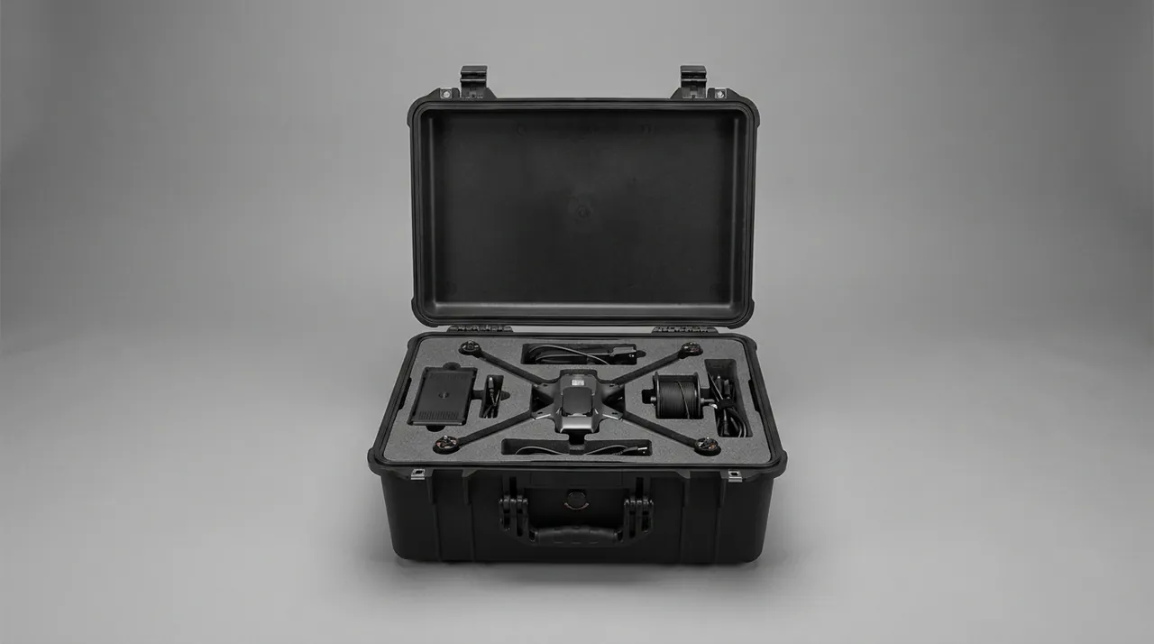
Like cutting tools, glue system components circulate: removed, sent for repair or cleaning, returned to the machine. A rotation case should be designed around that loop.
Physical separation of incoming and clean parts. Parts going out for service carry adhesive residue and dust, while returned parts must be clean, so the two must never share a cavity. Design an incoming zone and a clean zone separated by a solid wall or use two cases, with clear marking. The incoming zone can use smooth, easy-clean walls with a removable tray floor for chip removal, while the clean zone emphasises sealed cleanliness and corrosion protection.
Supporting the cleaning process. Where the customer uses cleaning equipment such as ultrasonic, solvent or purging systems, the packaging should make loading and unloading easy: chamfer or guard cavity mouths so repeated handling does not damage the liner, and provide replaceable liner modules. Parts coming out of cleaning often carry solvent residue, so confirm they are fully dry before wrapping.
Rotation count and maintenance. Number rotation cases and record trip counts, inspecting gasket compression, hardware condition and liner wear every six months or so, and renewing consumables in time. Where clean bags are used, state a replacement interval rather than reusing them until they fail. Practical cleaning and care methods are described in cleaning and maintaining a protective case. Where a rotation case also carries cutting tools, the guidance in cutter and spindle component protection can be applied to keep management rules consistent.
Marking and error prevention. Glue rollers and pressure rollers of similar diameter, length or texture are easily mixed up. Print specification and machine model on each cavity, or use colour-coded zones. For cases carrying several specifications, fit a document pocket inside the lid for the packing list.
Case life management. Over time hinges loosen, gaskets age and cavity geometry deforms. Set inspection intervals for key properties such as sealing, hardware function and liner geometry, and run a structural assessment after the design trip count before deciding whether to keep the case in service. The reasoning behind such decisions is set out in protective case service life and replacement criteria.
Selection comparison and cost structure
Selection for edge banding cases is governed by cleanliness requirement, number of trips and site conditions. The table below recommends a configuration for each common scenario.
| Scenario | Component profile | Recommended case | Liner and packing | Cost focus |
|---|---|---|---|---|
| --- | --- | --- | --- | --- |
| Glue assembly with a new machine | Medium size, high cleanliness | Injection PP or rotomoulded PE case with gasket | Closed-cell EVA cavities plus clean bags | Liner cleanliness and wrapping |
| Glue roller and shaft spares | Slender, patterned face | Aluminium frame or long-cavity timber case with vent | Suspended cradles, film, desiccant | Location structure and non-contact design |
| Pressure roller assemblies, batch | Cylindrical, coated face | Rotomoulded case with replaceable hardware | Split half-cradles plus sleeves | Cradle accuracy and sleeve material |
| Heating and electrical modules | Powered, moisture sensitive | Sealed case with antistatic liner | Antistatic foam plus moisture-proof wrap | Antistatic and moisture-proof material |
| In-plant rotation | Mixed serviceable and clean items | Castor case used as two separate units | Removable tray floor plus modular cavities | Cleanability and maintenance access |
Cost distribution is roughly 30 to 45 percent for case structure, 30 to 45 percent for liner and location, 10 to 15 percent for sealing and dehumidification, and 5 to 10 percent for consumables and marking. For this class of case, the liner and clean wrapping share is typically higher than in other industrial cases, because cleanliness determines whether the component installs correctly on the first attempt. Where a customer wants to reduce unit cost, the sound route is to increase reuse of case and liner through more trips and replaceable modules, rather than lowering the cleanliness standard of materials.
Hardware selection for hinges, latches and handles is covered in custom case lock options, and the combination of insert forming with cleanliness requirements in EVA insert forming and inspection.
Prototyping and supply models
Customisation for edge banding component cases should follow six gates.
- Requirement confirmation: component list with sensitive face locations and cleanliness requirements, maximum envelope and weight, transport and rotation method, cleaning process, environmental conditions;
- Design: case structure including sealing and antistatic needs, liner form and material, wrapping layers, hardware and mobility;
- First article: build the first case and check physical fit, confirming sensitive-face clearance and the pick path;
- Cleanliness verification: clean the liner and cavities, then run white cloth wipe and visual checks to confirm no debris or powdering;
- Pilot run: verify liner manufacturing consistency and wrapping process stability;
- Batch production and pre-shipment check: sample to the agreed plan and release each packing list with its inspection records attached.
Three problems dominate first-article rework. The first is insufficient clearance at sensitive faces, where liner and component tolerances stack; design a nominal clearance of at least 3 mm. The second is confusing wrapping layers, where the site cannot tell how many layers to remove; state the number of protective layers and the removal sequence on both drawing and packing list. The third is an unstated cleaning requirement, where the customer uses solvent cleaning on site but the liner material is not solvent resistant; confirm cleaning medium and temperature at requirement confirmation.
Common edge-banding case formats are held in stock, and non-standard bodies and inserts are made to the supplied drawing. Where the customer is a machine builder, the complete packing package can be scheduled to match the assembly takt. For distributors, combined configurations with mixed specifications make it easy to build a case to order.
Manufacturing and delivery are handled by Kexin New Materials (Guangdong) Co., Ltd. Cooperation models include wholesale supply, agency distribution, OEM and ODM customisation and global dispatch to overseas customers; cleanliness or material compliance documents can be provided once written into the contract terms, including liner material statements, cleanliness inspection records and test reports to the agreed standard.
Frequently Asked Questions
Q: What is the biggest difference between an edge banding component case and an ordinary equipment case? A: The acceptance standard shifts from whether anything was struck to whether anything was contaminated. Ordinary equipment cases focus on structural strength and cushioning, while failures in glue and pressure roller components are mostly contamination-type failures: glue roller texture packed with cured adhesive, hard particles embedded in roller faces, damp and oxidised heating tube terminals. What these share is that they are largely invisible from the outside and only appear at commissioning, making diagnosis expensive. Three extra design considerations follow. First, liner cleanliness: materials must not shed, migrate or exude. Second, compartmentalisation: separate components with different sensitive faces so they cannot contaminate or strike one another. Third, a clear wrapping hierarchy from the inside out, with every layer numbered and with removal instructions, so nobody leaves a film on or breaks a clean seal early. Acceptance should also add cleanliness items such as white cloth wipe checks on liner and cavities and visual checks for adhesive residue and particles on sensitive faces, with the criteria written into the technical annex.
Q: Why must glue rollers and pressure rollers always be stored in separate compartments? A: Because their sensitive faces are fundamentally different, and a shared compartment damages both. Glue roller texture is often only a few tenths of a millimetre deep and suffers when packed with hard particles or scored, and once damaged the adhesive distribution changes. Pressure rollers, especially coated ones, suffer from concentrated load indentations and cuts. In a shared cavity, transport vibration brings the hard end face or bearing housing of a pressure roller repeatedly against the patterned face of a glue roller, which can both mark the texture and transfer adhesive debris to the roller end. Conversely, cured adhesive particles from the glue roller can transfer onto the pressure roller face during vibration and form hard high spots that appear as shiny marks on the banded edge. Separate them into compartments with a solid wall: suspend the glue roller on its journals with the pattern floating, and support the pressure roller in a split half-cradle with the face floating and axial restraint at both ends. Mark each cavity with the component specification to prevent wrong fitting.
Q: The parts still have adhesive on them when removed; can we box them and clean later? A: Not advisable. Residual adhesive cools and cures inside the case and combines with dust into hard particles that are difficult to remove, and those particles are then driven further into sensitive faces or transferred to other components by vibration. Adhesive carried into the case can also contaminate the liner, requiring a full replacement, which costs more than cleaning properly in the first place. The correct approach is to drain and clean while the adhesive is still soft, using a dedicated cleaner or purging compound and avoiding metal scrapers. Let the part cool to room temperature, wipe with a lint-free cloth, dry fully, then wrap immediately. For glue roller texture, clean the grooves with a soft brush and cleaner. Where site conditions genuinely do not allow thorough cleaning, at minimum drain and wipe, state in the handover notes that a second cleaning is required on arrival, and use replaceable clean bags instead of a fixed liner so the case is not contaminated.
Q: How does a coated pressure roller usually get damaged in transit? A: Three ways. The first is permanent indentation from concentrated load: if a roller rests on point supports or is pressed against a hard item for a long period, the coating takes a permanent set that shows as uneven pressure or roller marks on the band after installation. The second is cutting: sharp metal edges, screws or tools cutting across the coating under vibration leave incisions that can propagate in service even when shallow. The third is adhesion and ageing: some protective materials, including soft PVC containing plasticiser, migrate plasticiser or stick to the coating over time, tearing the surface when removed. Protection measures include floating the face with weight carried at the journals, using a soft radiused cradle that produces line contact, fitting a clean sleeve with a small gap or anti-stick interlayer between sleeve and coating, and never sharing a compartment with other components. For longer transport periods, inspect sleeves periodically and confirm before installation that the coating shows no indentation or adhesion.
Q: How much desiccant should be used, and where should it go? A: Dose by internal net volume with at least 30 percent margin, and distribute it where air can reach rather than piling it in one corner. Understand that desiccant addresses internal humidity only. If components carry adhesive residue, cleaner residue or incomplete drying before packing, desiccant cannot remove the corrosion risk those contaminants create. If the case does not seal, desiccant saturates quickly. If the closing environment is very humid, above 80 percent for example, internal moisture starts high and desiccant is consumed far faster than expected. Pair it with a humidity indicator card whose colour change records the humidity peak during transit and provides objective evidence that the moisture protection worked. For sea freight or long storage, use a replaceable desiccant bay so maintenance does not require repeated opening of the main cavity. Also check chemical compatibility, avoiding formulations with a corrosion-promotion risk for the metals present. Around glue system parts, position desiccant bags away from any wrapped face so they cannot abrade a texture in transit.
Q: What should we watch for with powered parts such as thermostats and heating tubes? A: Moisture, static and impact. On moisture, damp or dirty heating tube terminals raise contact resistance and cause local overheating, so wrap the terminal area in moisture-proof material inside a clean bag and add desiccant to the cavity; thermostats should not be left exposed in humid air for long periods. On static, thermostats, inverters and servo drives are static-sensitive, so use antistatic liners and antistatic packing, add an ESD warning to the case marking, and require site personnel to follow ESD handling rules. On impact, a heating tube is a slender tube that bends easily, so place it in a long cavity with end guards, coil and secure any lead wires so they cannot be pulled, add a soft protective layer over thermostat displays so they are not compressed, and guard thermocouples and probes so bending does not shift measurement accuracy. Powered components should also have insulation and short-circuit prevention in transit so terminals cannot contact each other.
Q: How should a rotation case serve both incoming service parts and clean parts? A: Physical separation and cleanability are the keys. For separation, design an incoming zone and a clean zone in the same case, divided by a solid wall and marked with clear colour coding; where contamination levels differ greatly, use two separate cases to avoid cross-contamination. For cleanability, make the incoming zone walls smooth and easy to wipe with a removable tray floor for clearing adhesive debris, while the clean zone emphasises sealed cleanliness and corrosion protection with desiccant and a humidity indicator. Handle cavity mouths by chamfering or fitting guard strips so repeated handling does not score the liner, and use replaceable modules at high-wear positions so local damage does not scrap a whole insert. Number each rotation case, record trip counts, and inspect gaskets, hardware and liner condition periodically, renewing consumables in time. Parts coming out of cleaning often carry solvent residue, so confirm they are fully dry before wrapping and choose solvent-resistant wrapping material.
Q: What extra packaging points apply to export orders? A: Four areas. First, test reference selection: the domestic leg can follow the domestic transport packaging test series, while cross-border orders suit a distribution cycle approach for combined sequences plus whole-case verification; where a customer cites military environmental test methods, explain that only the method is referenced rather than a certification. Second, moisture and temperature response: a sea voyage may exceed 30 days, so provide a replaceable desiccant bay, humidity indicator cards and a hydrophobic breather vent, and keep the closing environment at 45 to 55 percent RH. Third, marking and documents: use bilingual marking with illustrated unpacking guidance, and provide a document set containing the packing list, liner material statement, cleanliness inspection records and protective layer removal instructions. Fourth, regulatory and handling conditions: where cells or other regulated goods travel with the case, the transport paperwork is issued as a separate set, and confirm the destination's forklift or lifting capability, mark centre of gravity and stacking limits, and provide lifting points where needed. For high-cleanliness components, also state the required unpacking environment so the customer can prepare in advance.
Q: How do we judge whether a liner meets the cleanliness requirement? A: Check three levels. At material level, confirm the liner is closed-cell and low-exudation, and request data on water absorption, compression set and compatibility, avoiding open-cell sponge, cheap powdering foam and soft PVC containing plasticiser. At process level, whatever forming method is used, debris must be fully removed after machining: clean fine particles from CNC cavities, ensure die-cut edges are burr-free and non-powdering, and confirm mould release residue is removed from thermoformed parts. At finished-product level, use a white cloth wipe test, rubbing the cavity walls and floor firmly with clean white cloth and checking for visible particles or powdering, alongside a visual check for metal chips, oil and adhesive residue. For orders with high cleanliness requirements, face the liner with a replaceable clean film, which both raises cleanliness and simplifies maintenance. Writing these checks into the acceptance conditions closes the gap between looking clean and actually meeting the requirement. Repeat the wipe test on a sample from each production batch rather than only on the first article, because machining debris varies with tool wear over a production run.
Conclusion and related reading
The difficulty with edge banding component cases is not structural strength but turning cleanliness into a deliverable, inspectable engineering specification. From cleaning and draining as a prerequisite, through compartmentalisation and floating sensitive faces, to liner cleanliness, wrapping hierarchy and dehumidification, every link shows up at commissioning as adhesive uniformity, roller marks or terminal contact behaviour. For buyers, the highest-value action is to state sensitive face locations, cleaning media and cleanliness requirements before ordering, and to complete physical fit and cleanliness verification at first-article stage rather than tracing a packaging cause after commissioning problems appear.
Where a customer also handles woodworking cutting tools and spindles, the guidance in cutter and spindle component protection can unify rotation equipment standards; where press and hydraulic components are involved, the contamination and moisture control logic in press platen and hydraulic component protection applies directly. For cavity design and verification of custom inserts, see custom foam insert design and validation. For high-cleanliness, maintainable rotation cases, see the removable divider system and identifying case material and build quality.
Related reading