


A woodworking machine case has to contain two opposite types of fragility: a cutting edge that fails if it is touched at all, and a spindle fit surface that fails through contamination and progressive damage. Moulding cutters, finger-joint heads and diamond saw blades hold very high edge hardness but are brittle, and a micro-chip on the edge shows up immediately as ripple on the machined surface. Spindle and cutter-shaft tapers, bearing shoulders and keyways are fit surfaces; any indentation, rust bloom or embedded chip changes radial runout after assembly. Putting both families into one woodworking equipment component case means working to three rules rather than wrapping everything in foam: keep the cutting edge floating, keep the fit surface sealed, and let structure, not cushioning, carry the mass.
This guide is written for equipment managers at furniture and door plants, tool-crib supervisors and woodworking machinery distributors. It starts from risk classification, then covers cutting-edge guard design, spindle dynamic balance protection, liner forming processes, test criteria and the packaging loop for tool re-sharpening, closing with FAQs and further reading that can be attached directly to a purchase specification.
Contents
- Cutting edges and fit surfaces: two opposite fragilities
- Component families and risk classification
- Cutter cases: edge guards and tooth-form isolation
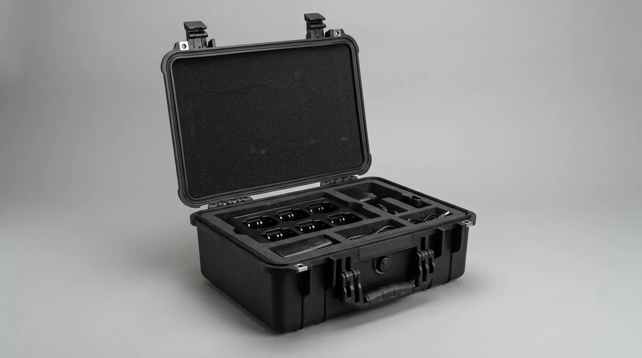
- Spindles and cutter shafts: balance and fit-surface protection
- The double boundary of rust and corrosion control
- Comparing liner forming processes
- Hardware and closure mechanisms
- Sealing, cushioning and environmental preconditioning
- Validation: from distribution cycle to drop
- Marking, traceability and unpacking practice
- Prototyping and batch consistency
- Tool re-sharpening loops and spare rotation
- Frequently Asked Questions
- Conclusion and related reading
Cutting edges and fit surfaces: two opposite fragilities
Consider a scene that repeats in every plant. A team changes a set of moulding cutters and drops the old ones into a tote. On the way to the tool crib the cutters knock against each other. The spindle pulled at the same time has no proper cradle, so it leans against the tote wall and its taper grazes sawdust left in the bottom. At the next installation, the cutter edges already carry chips too small to see, the spindle runs out beyond tolerance, the finished surface shows periodic ripple, and quality control starts looking for a cause. The real loss happened during handling, before anyone touched the machine.
Cutters and spindles must be treated differently because their failure logic is different. Cutter failure is instantaneous: one impact is enough to cause irreparable edge damage, and the tool often keeps cutting afterwards, pushing the problem downstream into finished product where diagnosis is expensive. Spindle failure is cumulative: a light indentation on a fit surface may go unnoticed, but at high rotational speed it is amplified into vibration and temperature rise, ending in premature bearing failure. The primary specification for a cutter case is therefore that peak impact load at any point stays below the edge damage threshold, while the primary specification for a woodworking spindle case is that fit surfaces see no contact contamination and no local indentation throughout the journey.
Translated into design language, that gives three statements. Cutting edges and tooth forms must float or be independently isolated. Fit surfaces must sit in a clean, dry, controlled environment. The weight of the mass must be carried by structural members rather than by the cushioning layer. The following sections work through the component families one by one.
Component families and risk classification
Classify before designing. A risk ranking is more economical and more effective than specifying the thickest foam everywhere. The three inputs are fragility of the edge or fit surface, the stiffness of the component itself, and replacement cost and lead time. The table below ranks common woodworking spares and pairs each with a packaging strategy.
| Component | Fragile feature | Risk level | Packaging strategy |
|---|---|---|---|
| --- | --- | --- | --- |
| Diamond moulding and finger-joint heads | Very brittle edge, complex tooth form | High | One cavity per piece, edge guard, desiccant |
| Tungsten carbide saw blade | Chipped tooth, body flatness | High | Vertical slot, suspended, teeth free |
| HSS cutter shaft and router bit | Cutting edge and shaft runout | High | Edge sleeve plus journal cradle |
| Spindle assembly with taper | Taper indentation, embedded chip | High | Taper guard, sealed cavity, VCI |
| Feed and pressure wheels | Face scoring, runout | Medium | Floating face, end restraint |
| Servo motor and gearbox | Shaft corrosion, encoder end | Medium | Shaft cap plus simple-support cradle |
| Sprockets and gears | Tooth-form impact | Medium | Dedicated tooth cavity |
| Pneumatic and hydraulic cylinders | Bore scoring, bent rod | Medium | Bore clamp plus rod sleeve |
| General fasteners | Mixing, surface damage | Low | Compartment tray plus marking |
| Belts and hoses | Deformation, ageing | Low | Coiled and secured, light excluded |
Ranking is not about labels; it is about directing cost where it counts. Two kinds of waste are common. One is giving low-risk fasteners a high-density EVA cavity, which adds cost without adding reliability. The other is mixing high-risk moulding cutters with general hardware, so the low-value items damage the high-value ones. Segregate by risk: pack high-value cutting tools and spindles in their own cases, general parts in another, and mark no-mixing instructions on the packing list. Because density, water uptake and compression set of liner foams vary widely and dominate long-term protection, check each option against our case foam material comparison before fixing a grade.
One further variable is the number of trips. Tooling that ships once with a new machine and tooling that travels back and forth for re-sharpening call for entirely different case design. The former can lean towards a light, one-way solution; the latter must be maintainable and repairable. Ask this question at the selection stage rather than after the first return shipment.
Cutter cases: edge guards and tooth-form isolation
Cutter protection works on three levels: the edge, the tooth form and the body.
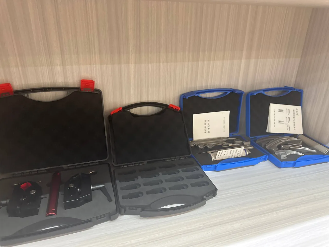
Edge guards. The cutting edge is the hardest and most brittle feature, and a guard works not by pressing on it but by preventing any hard object from reaching the edge line. A common approach is a single-piece extruded or moulded PE or PVC guard with 1 to 2 mm clearance to the edge, located off the tool body face. The guard must be one piece; splices become friction points that can be worse than no guard at all. Orient the opening downward or inward so dust does not collect near the edge.
Tooth-form isolation. On moulding and finger-joint heads the tooth forms engage each other easily. If two heads sit side by side, vibration lets the teeth gnaw at one another and both are damaged. Use a die-cut cavity array with one position per piece, a solid wall of at least 8 mm between cavities, and no channel through which two tooth forms can meet. Add a 3 to 5 mm floor slope or finger notch so each piece can be lifted out without prying.
Body protection. A carbide saw blade is a thin, large-diameter item that must never be stored flat under face pressure. Stand it vertically on a locating arbor through the bore, or use a double-sided clamping slot so the rim supports the body and the bore locates it. Keep at least 25 mm between blades, and line the slot with 3 mm EVA or cork so the carbide teeth never strike the wall.
An easily overlooked detail is the transport orientation and work sequence. If the customer goes straight from case to machine, orient the tool close to its installed attitude to minimise handling. If tools go into a store first, the cavity height and case dimensions must guarantee that tooth surfaces are not loaded during stacking. These two scenarios demand different answers and must be confirmed at design stage.
Humidity control inside a cutter case should be stronger than in a general parts case. On hardened edge materials, corrosion usually starts at the boundary between ground edge and body, and once it forms the edge geometry changes. Place desiccant and an indicator card near the cutter cavities and dose by internal net volume; piling desiccant in one corner leaves the rest of the case unprotected.
Spindles and cutter shafts: balance and fit-surface protection
A spindle is the accuracy datum of a woodworking machine, so its transport protection is about preventing deformation and contamination rather than preventing fracture.
Support arrangement drives deformation control. A spindle has a high length-to-diameter ratio. Supported only at two ends with the middle hanging free, transport vibration will excite bending modes and can leave residual deformation after long exposure. Use three or four supports: one cradle at each journal, plus one or two intermediate cradles spaced along the span. Line the cradles with closed-cell EVA or polyurethane at moderate hardness so no indentation is pressed into a journal. Contact should be line contact or a face with a rounded transition, never a hard edge pressing on a journal.
Taper and keyway are the two contamination priorities. A taper is a fit surface, and any chip, grit or rust spot directly changes runout after tool fitting. Clean the taper before packing, apply a thin preservative oil film, and cover with a guard whose inner surface is a clean, non-shedding material. Keyways and bearing shoulders need the same treatment, because a keyway edge is easily raised into a burr by another hard part. Place the whole spindle in a dedicated sealed cavity with vapour phase corrosion inhibitor so the assembly sits in a controlled micro-environment isolated from workshop air.
Notes on dynamically balanced assemblies. If the spindle carries balance weights, balance rings or sensors, ensure nothing shifts or loosens in transit. Provide small dedicated pockets for accessories with soft retaining blocks so an accessory cannot come loose and strike the spindle. Sensor-equipped assemblies also need static control and cable protection; coil and secure cables so they cannot be stretched or crushed. Where a customer runs several spindle variants, a removable divider system can carve a single case into independent zones and keep flexibility without losing isolation. General protection practice for machine tool spindles is covered in CNC spindle component protection.
For complete spindle units with motor and pulley, add lifting and tipping risk to the design brief. Mark the centre of gravity, provide lifting ears where useful, and widen or brace the base if the case is tall. For export orders, confirm what lifting equipment the destination actually has, so the case is not designed in a way that cannot be safely rigged on site.
The double boundary of rust and corrosion control
Woodworking plants create a specific environment. Airborne wood dust absorbs moisture and becomes mildly acidic, forming local corrosion cells where it settles on metal, while machining some hardwoods and panel products releases organic acids that also accelerate corrosion. Corrosion design for woodworking machine cases therefore cannot be copied from general machinery practice; it must account for dust contamination and organic acids as separate variables.
Cleaning before packing is the first line. After removal, blow off dust with compressed air, wipe with a neutral cleaner and dry thoroughly. Do not use chlorinated solvents, which can trigger stress corrosion, or strong alkaline cleaners, which can attack protective coatings. Move to preservation quickly after cleaning, because in a dust-heavy shop a cleaned metal surface can be recontaminated within hours.
Match the preservation method to the part. Cutting tools suit vapour phase inhibitor materials, which reach into gullets and other areas that oil cannot cover. Spindles suit a combination of thin oil film and guard, because fit surfaces need an even, thin film and heavy grease creates cleaning work before assembly. Dose and distribute by internal volume rather than stacking everything in one corner.
The internal environment must be controlled, not merely sealed. A fully sealed case develops negative pressure under temperature cycling and draws moisture in, so fit a hydrophobic breather vent to equalise pressure while using desiccant for residual moisture. Keep the membrane away from positions where water could pool on top, so it is not damaged by water pressure or debris over repeated use. For high-value spindles, add both a humidity indicator card and a single-use shock indicator, turning the questions of whether moisture entered and whether an out-of-limit impact occurred into readable records.
Finally, require neutral materials. Timber liners and paper-based materials can release organic acids in a long closed environment and produce the corrosion pattern known as crate rust or paper rust. If a timber structure is required, place an independent barrier layer such as VCI film or aluminium foil laminate between wood and metal and ensure it stays intact. Foam must also be checked for metal compatibility, particularly recycled material of unknown origin.
Comparing liner forming processes
The liner sets the protection ceiling, and its forming process sets the cost structure, lead time and consistency. The table below compares four common processes by batch size and accuracy.
| Process | Accuracy | Tooling and setup | Best batch | Main limitation |
|---|---|---|---|---|
| --- | --- | --- | --- | --- |
| CNC machining | High, 3D surfaces and deep pockets | Low, programming only | One-off, small batch, irregular shapes | Long cycle per piece, material waste |
| Die cutting | Medium, constant-thickness sheet | Medium, die required | Medium to large, regular outlines | Limited depth, no 3D surfaces |
| Thermoforming | Medium-high, composite structures | High, mould required | Large, standardised cavities | High setup, costly to change |
| Assembled modules | High, freely configurable | Low to medium | Mixed items, maintainability | Depends on assembly accuracy and fixing |
The selection logic reduces to three statements. Choose CNC for irregular, one-off or high-accuracy work. Choose die cutting or thermoforming where the batch is stable and cavities are regular. Choose assembled modules where on-site replacement and multiple variants coexist. In practice the most common hybrid is a formed or die-cut body with CNC finishing on critical cavities, which balances cost and accuracy.
Material layers follow the same logic as the cavities. Use high-density EVA at 70 to 90 kg/m³ or cross-linked PE as the load-bearing layer, 25 to 45 kg/m³ PU or PE as the energy-absorbing layer, and a non-shedding, low-absorption face material where precision surfaces touch, adding flocking or fabric facing where lower friction helps. Compression set varies considerably between materials, so request compression set data rather than comparing density alone.
Never rely on friction alone to hold the liner. Use detachable clips, hook-and-loop or counterbored screws so the liner cannot shift as a unit in transit. Where the customer wants to lift the liner out and use it as a tray, combine locating dowels with handles so the insert genuinely works as a removable carrier.
Hardware and closure mechanisms
Hardware is the most underrated element. Many cases perform well on the first trip and then show gasket leakage, lid movement or latch release after a dozen opening cycles, and the root cause is always hardware.
Hinges. For tool cases opened frequently, choose a hinge with a stay or limit function so the lid cannot fall under its own weight onto an operator's hand, and so the lid does not slam into the body and disturb the gasket. Fix hinges with screws rather than rivets so they can be replaced on site, and use fasteners with anti-loosening features. For heavy lids, use double hinges or extended hinge bases to spread load into reinforced wall sections.
Latches. A latch does more than lock: it applies even compression so the gasket reaches its design squeeze. Choose latches with tension adjustment or a self-locking action rather than economy designs that rely purely on plastic deflection. Where tamper evidence matters, specify a latch that accepts a security seal and provide a padlock hole.
Other details. Breather vents, handles, castors and telescopic handles are functional accessories whose reliability shapes the user experience. Recess handles to avoid impact damage in transit. Castors and handles suit cases that move frequently, but remember that castors become load points during stacking and need structural reinforcement. Where forklift handling is expected, match the fork pocket height to common tine dimensions.
A simple way to judge a hardware package is to run 20 consecutive open and close cycles fully loaded and watch whether gasket compression fades, the lid shifts, or the latches need extra force. A configuration that passes this check will normally support a long service life. Our guide to case hinge, latch and seal coordination explains the interaction between the three, and where a dust or water ingress rating is required, confirm the target against IP rating and water ingress testing.
Sealing, cushioning and environmental preconditioning
Sealing and cushioning are invisible design decisions that determine how stable the internal micro-environment stays.
Sealing. Gasket selection must balance compression set, rebound and temperature range. Foamed silicone suits wide temperature ranges and high rebound requirements. EPDM offers strong weather resistance at moderate cost and fits most industrial sites. Nitrile rubber resists oil and suits areas with grease exposure. Specify a double-lip case mouth so contact pressure survives repeated cycles, and use a groove-mounted gasket that can be replaced on site without damaging the case.
Cushioning. The common mistake is assuming thicker is better. Absorbed impact energy depends on thickness, density and contact area together; an overly thick soft foam compacts and bottoms out quickly, which actually raises peak acceleration. Derive cushion thickness and density from the component's fragility and allowable acceleration, then verify by drop test. For high-value cutting tools, run an actual drop screening rather than relying on experience.
Environmental preconditioning. Where the route crosses humid regions or involves sea freight, precondition components in a low-humidity environment and fit desiccant with a humidity indicator. Control the humidity of the closing area itself, ideally 45 to 55 percent RH, and consider a replaceable desiccant bay for parts held in long storage.
Cushioning materials must also be non-absorbing, non-shedding and non-corrosive. Some low-cost foams hold water after absorption and become a moisture source inside the case, while others crumble under sustained compression, sending debris into spindle tapers and guide surfaces. Ask suppliers for water absorption and compatibility data before selection.
Validation: from distribution cycle to drop
Validation for woodworking machine component cases revolves around realistic distribution conditions rather than isolated tests.
Reference standards. International distribution cycle simulation is represented by ASTM D4169, which decomposes transport into handling, stacking, vibration and impact and combines them into a test sequence suited to cross-border orders; sequencing and intensity levels are explained in our notes on using ASTM D4169 distribution cycle testing. Domestic transport can reference the GB/T 4857 series, while ISTA programmes emphasise reproducible whole-case performance. Where a customer cites military environmental test methods, reference the relevant methods in MIL-STD-810H, noting clearly that this is a method reference and not a military certification.
Recommended test set. For cutter and spindle cases, complete at least environmental preconditioning with temperature and humidity cycling, random vibration to confirm that edges and cavity walls do not abrade and that fit surfaces are not scored, stacking to confirm lid and liner clearance, drop or incline impact to confirm corners and cradles, and low-frequency impact screening for high-value items. Inspect and photograph every cutting edge and fit surface afterwards.
Quantitative criteria. Criteria must be measurable or responsibility cannot be assigned. Examples include no new edge chipping at the agreed inspection magnification, body flatness change within an agreed range, no significant change in spindle runout compared with pre-shipment values, liner displacement under 2 mm, no visible condensate, and hardware functioning normally.
Reports and agreements. State test items, sequence, criteria, sample size and failure disposition in the technical annex. For repeat customers, freeze a standard validation plan and add only the differences when components change, which protects reliability while controlling cost.
Marking, traceability and unpacking practice
A marking system looks secondary but directly affects on-site work quality and responsibility boundaries.
External marking. Include component name and number, quantity, packing date, batch, gross weight, centre of gravity, stacking limit, orientation and moisture warnings. For export orders, use bilingual labels with pictograms to reduce language barriers. Where electrostatic-sensitive parts are packed, add ESD marking and use antistatic liner material; where lithium batteries ship with the case, mark them under the applicable transport regulations.
Liner marking. Print item numbers and cavity numbers on the liner so operators can count and return parts without consulting the packing list. For cutter cases, print specification and machine model next to each cavity to reduce wrong installation.
Unpacking and returning. Supply illustrated unpacking and returning instructions covering opening sequence, pick sequence and prohibited actions, such as prying the liner near a cutting edge with a metal tool. Where parts go out for repair, reserve a dedicated repair cavity so serviceable and unserviceable items are never mixed.
Traceability. For high-value cutters and spindles, keep a case-number record of each shipment date, destination and unpacking result. This record is valuable in disputes and also reveals weak points in the protection scheme over time.
Prototyping and batch consistency
How disciplined the customisation process is determines first-article pass rate and batch consistency. Work through these gates.
- Requirement collection: component list with maximum envelope, weight, centre of gravity and edge or fit-surface locations, plus transport mode, number of trips, environment and export status;
- Design: fix case structure, liner process, sealing and cushioning, hardware, and issue drawings with a bill of materials;
- First article: build and check physical fit, with drop or vibration screening where needed;
- Fit confirmation: run a full pack, simulated transport and unpack drill with the real component to confirm the pick path works;
- Pilot run: verify liner manufacturing consistency and assembly cycle time;
- Volume production and shipment inspection: freeze parameters, inspect per the agreed sampling plan, issue records.
The two most common causes of first-article rework are a mismatch between the physical part and the drawing, and an unclear packaging unit definition. Solve the first with measured key dimensions or 3D scanning, and the second by issuing a packing list template at order confirmation for item-by-item sign-off. For cutters, also confirm edge orientation and guard type to avoid problems such as a guard fitted the wrong way round, which is trivial to fix and expensive to discover late.
Batch consistency comes down to three variables: liner material batch, including density and hardness; process parameters, such as machining tolerance or die wear; and gasket compression achieved at assembly. Sample material density per batch, sample critical cavity dimensions per batch, and check closure and sealing on every finished batch.
Tool re-sharpening loops and spare rotation
Woodworking tools are classic circulating assets: removed when blunt, sent for re-sharpening, returned to the shop. Every leg of that loop is an exposure, so a rotation case must be designed around circulation.
Durability matched to frequency. Use replaceable hinges and latches, a cartridge gasket that can be pulled out and renewed, a modular liner with individually replaceable cavities, and sacrificial corner bumpers. These measures convert total case scrap into local replacement and cut long-term cost markedly.
Configuration for re-sharpening. Tools going out for service carry oil and dust, so provide separate physical zones for incoming and finished items to prevent cross-contamination. The incoming zone can use smooth, easy-clean walls with a removable tray floor for chip removal, while the finished zone emphasises cleanliness and corrosion protection with VCI material and a humidity indicator.
Design against wrong fitting. Specification variety invites mix-ups. Reduce the probability with printed cavity text, colour-coded zones or drawer compartments, and fit a document pocket inside the lid for the packing list so counts can be checked.
Rotation records and life-cycle management. Number every rotation case and record trip counts and maintenance actions, for example checking gasket compression and liner wear every six months and renewing consumables. For cases beyond their design trip count, inspect structurally before returning them to service so an ageing case does not create a batch transport risk.
One final caution: the re-sharpening loop often involves short distances but many handlings. Repeated handling damages corners, latches and cavity mouths more than long-distance travel does. Treat handling intensity as an independent design input. Where a customer also circulates sawmill blades and feed spares, building the sawmill equipment component case to the same logistics unit format keeps shop and tool-crib containers interchangeable and simplifies management.
Frequently Asked Questions
Q: Why should moulding cutters and saw blades never travel in the same case? A: The main reason is that their fragile features differ and they damage each other. Moulding heads have complex tooth forms that engage readily, so in a shared cavity vibration lets teeth gnaw at one another and both are usually ruined. Carbide saw teeth are hard enough that impact chips them while also raising hard scratches on whatever they touch. In a shared case, the rim of a saw blade acts like a knife on moulding cutter edges, while a carbide tooth can crack when it strikes the heavier steel body of a cutter head. Separate them into zones or separate cases. Blades should stand vertically in slots, supported at the rim and located on the bore. Moulding heads belong in die-cut cavities with one position per piece plus an edge guard. If co-shipment is unavoidable, install a solid dividing wall, keep at least 30 mm between the two families, and never share a single cavity array between them.
Q: Should a spindle be oiled before packing, and how thick should the film be? A: Yes, but distinguish between surfaces and keep the film thin. On tapers, keyways and bearing shoulders, apply a thin, even rust-preventive oil film that is continuous but not running; a visible sheen that leaves a light mark on a finger is about right. Heavier grease creates cleaning work before assembly, and incomplete cleaning can contaminate the taper fit. For splines and tooth faces, brush the oil into the roots. Cosmetic surfaces can be treated more simply. Beyond oil, use a guard plus a vapour phase inhibitor: the guard prevents mechanical contact while VCI material forms a molecular adsorption layer inside the sealed cavity, covering areas that are difficult to oil. Clean before packing, removing dust, chips and hand sweat, otherwise the oil film traps contaminants against the metal and accelerates local corrosion. For sea freight or high humidity, add a humidity indicator card and desiccant, and inspect within 24 hours of arrival. Cleaning is only meaningful once drying is complete, so confirm the surface is fully dry before the oil film goes on, and re-clean rather than top up a film that already carries grit.
Q: Is CNC machining or a die-cut mould more economical for the liner? A: It depends on batch size and cavity shape. CNC requires no tooling and suits one-off, small-batch and irregular cavities, especially spindles needing 3D surfaces and deep pockets. Its drawbacks are long cycle time per piece and low material utilisation, so unit cost does not fall with volume. Die cutting suits constant-thickness sheet and regular outlines, with low unit cost and good consistency once the die exists, but depth is limited, 3D surfaces are impossible, and a worn die needs re-sharpening or replacement. Thermoforming suits large batches and standardised cavities with high setup but excellent consistency and efficiency. In practice, the common hybrid is a die-cut or thermoformed body with CNC finishing on critical cavities, which controls cost while holding accuracy where precision surfaces touch. Where the product line changes often, favour CNC and assembled modules, accepting higher unit cost in exchange for flexibility to modify. Whichever route is chosen, state the finishing operation on critical cavities explicitly in the drawing, because a cavity cut to nominal size without clearance can grip a spindle taper too tightly.
Q: Is fitting desiccant inside a cutter case enough to stop corrosion? A: No. Desiccant addresses internal humidity only, while corrosion results from humidity, temperature and contamination together. If dust, resin and hand sweat are not removed before packing, they form local corrosion cells on the metal that desiccant cannot eliminate. If the case does not seal, desiccant saturates quickly. If the packing environment is itself humid, internal moisture starts high and desiccant is consumed far faster than expected. A more complete approach has four steps: clean and dry before packing; choose preservation by component type, with VCI materials for cutting tools and a thin oil film plus guard for fit surfaces; fit a gasket and a hydrophobic breather vent to equalise pressure; and dose desiccant by net volume while monitoring with an indicator card. For long ocean voyages, use a replaceable desiccant bay and keep a humidity recording label as objective evidence. Where a cutter head combines materials, such as a steel body with brazed carbide tips, check that the preservation method suits both, because a product chosen for steel alone may not protect a brazed joint. Indicator cards should be read and recorded at receiving, with a colour change treated as a trigger for inspection rather than a note filed away.
Q: Hardware looks much the same; how can we judge quality? A: Three practical checks work well. First, fixing method: prefer screwed hinges and latches so they can be replaced on site, with anti-loosening fasteners; rivets may be stronger initially but mean the whole case goes back for repair when damaged. Second, compression adjustability: a latch should apply even, sustainable compression so the gasket reaches its design squeeze, rather than relying on plastic deflection as economy designs do. Third, endurance: run 20 consecutive open and close cycles fully loaded and watch whether gasket compression fades, the lid shifts, or latches need extra force. A configuration passing this check normally supports a long service life. Accessories matter too: recess handles so they do not break on impact, reinforce the structure where castors become stacking load points, and match fork pocket height to common forklift tines. Check the gasket groove geometry as well, because a gasket sitting in an oversized groove will not reach design compression even with a good latch, and the fault appears as dust ingress rather than as water leakage. Ask for gasket durometer and compression set data so replacement parts match the original.
Q: What extra packaging considerations apply to export orders? A: Four main areas. First, choose the environmental test reference: cross-border logistics suits a distribution cycle approach such as ASTM D4169, the domestic leg can reference GB/T 4857, and ISTA programmes suit reproducible whole-case verification; where a customer cites military environmental methods, state clearly that only the method is referenced. Second, address humidity and temperature cycling: a sea voyage may exceed 30 days, so provide a replaceable desiccant bay, humidity indicator cards and a pressure equalisation valve, and control the packing environment humidity. Third, handle marking and documents: bilingual case marking with illustrated unpacking guidance, and a document set containing the packing list, material and specification notes, required inspection records and consumable replacement instructions. Fourth, confirm lifting and stacking conditions at destination, mark centre of gravity and stacking limits, and provide lifting ears or a widened base where tipping is a risk. Where the customer works to an internal packaging specification of their own, obtain it before design rather than after the first article, because the test sequence and acceptance limits are usually fixed in that document. For any air freight leg, remember that pressure changes are faster than at sea and vent sizing should account for it.
Q: For sea freight, is a tighter seal always better? A: No. A fully airtight case develops internal negative pressure as voyage temperatures fall. That pulls the gasket tighter, and on opening creates an inrush of moist air or leaves condensate inside, which works against corrosion control. The correct approach is sealing plus controlled venting: a gasket blocks liquid water and dust while a hydrophobic breather vent high on the case passes air molecules to equalise pressure without admitting liquid water. Valve count follows internal volume and temperature swing; for large volumes and sharp swings, fit two in symmetrical positions to balance faster. Keep the installation point away from areas where water pools on top and protect the membrane with a raised boss. Where high-pressure washdown is routine, select a cover-protected version. Note that a vent does not replace desiccant or humidity monitoring; the three work together. For cutter cases specifically, the vent prevents a pressure differential from pressing the lid onto a cutter edge during a rapid altitude change on an air leg, a real risk when the case is only partly filled and the liner cannot support the lid.
Q: Does wood dust really affect precision components? A: Yes, and the effect is often underestimated. Wood dust absorbs moisture and becomes mildly acidic, forming local corrosion cells on metal that progress into pitting beneath contact points over time. Organic acids released when machining hardwoods and some panel products accelerate corrosion as well. Mechanically, dust and chips entering a spindle taper, keyway or guide will change the fit after assembly, increasing radial runout or causing motion to bind. Cleaning and drying cannot be skipped, and preservation should follow quickly so the part is not left exposed in a dusty shop. In case design, combine a sealed cavity with vapour phase inhibitor material so precision surfaces are isolated from the workshop environment, and select non-shedding, low-absorption liner materials whose metal compatibility is confirmed, rather than unknown recycled foam. Dust also enters through an unsealed case mouth during loading in the shop, so complete packing away from sanding and trimming stations. Where a component cannot be cleaned fully, note the residual condition on the packing list so the receiving team knows which faces to inspect first.
Conclusion and related reading
The difficulty of a woodworking machine component case is not the box but the need to serve two contradictory fragilities at once: a cutting edge that must never be touched, and a fit surface that must stay clean and stable. Only when that requirement is decomposed into component families, risk levels, guard design, liner process and quantitative test criteria does the protection scheme become verifiable. For buyers, the highest-value action is to hand over the component list, edge and fit-surface locations, transport route and acceptance criteria before ordering, and then run a full pack drill with real parts at the first-article stage.
The woodworking machine component cases described in this article are manufactured by Kexin New Materials (Guangdong) Co., Ltd., which also runs OEM and ODM programmes and supports wholesale, regional agency and overseas dispatch; material certificates and inspection reports are available within the contract framework on request. Where a liner must be adapted to a specific machine model, provide key measured dimensions or 3D scan data so fit confirmation passes at the first article.
Related reading