

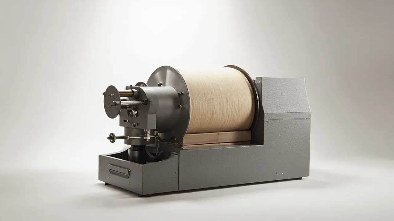
Spare-part packaging for rotary kilns, lime kilns and ceramsite kilns differs from general equipment cases in one decisive respect: load, not volume, governs the design. A single support roller assembly can weigh several tonnes, while a kiln shell section is a thin-walled cylinder with a very large slenderness ratio. Neither can be solved with ordinary foam liners. The correct sequence is: design the load-bearing structure from unit weight and centre of gravity first, then design support and contour matching from the contact geometry, and only then address sealing and moisture control. Reversing that order produces a case that distorts structurally during lifting or stacking, at which point the best sealing in the world achieves nothing.
This article is written for kiln overhaul projects in cement, lime, metallurgy and chemical plants, for kiln equipment manufacturers and for engineering contractors. It covers packaging methods for support rollers and tyres, kiln shell sections, girth gears, thrust rollers and bearing shells; design parameters for load-bearing bases and liners; rust and moisture control strategies for open yards and ocean freight; and marking and documentation requirements for out-of-gauge transport. Figures quoted are typical industry ranges and experience values; the governing references remain the project drawings, transport plan and contractual technical specification.
Table of Contents
- Why Heavy Load, Not Volume, Drives Kiln Component Case Design
- Support Rollers, Tyres and Bearing Shells: Preserving Fit Accuracy
- Transport Forms for Kiln Shell Sections and Ovality Control
- Load-Bearing Structure and Base Reinforcement for Large Cases
- Lifting Points, Centre-of-Gravity Marks and Out-of-Gauge Boundaries
- Cradles and Liners: From Sleepers to Moulded High-Density Blocks
- Rust and Moisture Control in Open Yards and Ocean Freight
- Sealing Systems, Breather Valves and Desiccant Sizing
- Transport Testing: Choosing Between GB/T 4857 and ASTM D4169
- Unpacking and Re-Inspection at the Site Staging Area
- Project Supply Packages and OEM Cooperation Models
- Out-of-Gauge Compliance, Marking and Shipping Documents
- Frequently Asked Questions
- Conclusion and Related Reading
Why Heavy Load, Not Volume, Drives Kiln Component Case Design
Weight distribution across kiln spares is extremely uneven. The support roller assembly holds the heaviest single casting on the whole kiln, the tyre is a heavy ring forging or casting, and the kiln shell section is not necessarily heavy but is a thin-walled long component with low stiffness. The failure mechanisms are therefore opposite: heavy parts risk crushing and local yielding, while thin-walled long parts risk loss of roundness and axial bending.
Put both families in one case and two contradictory demands appear. Downward, heavy parts require a base with enough compressive and bending stiffness, and that base cannot be improvised from loose timber. Upward, thin-walled parts require distributed support points with limited load per point, otherwise the shell section is dented locally at each support and its ovality is lost. Design only for the heavy item and the shell contact points are overloaded; design only for the shell and the heavy item bottoms out the compliant support and transmits shock directly.
The answer is layered load bearing: the bottom layer carries total weight and passes it into the case frame and the transport vehicle; the middle layer spreads the load; the upper layer matches the part contour. Load transfer interfaces between layers must be explicit, and stiffness should not change abruptly across an interface. In practice the combination used most often is a steel sub-frame, a high-density foam levelling layer and a moulded cradle matching the part contour. The reasoning parallels packaging practice for mill liner plates, described in heavy-duty packaging for ball mill liner cases.
One further principle is easily missed: the case is not the only load path. For very large or very heavy shell sections and rollers, the case often provides only dust and moisture protection plus restraint, while actual load bearing is handled by a steel base frame or dedicated saddle beneath it, with the case connected to the frame by releasable fixings. This lets the site lift the base directly during handling, keeping load out of the case walls.
Support Rollers, Tyres and Bearing Shells: Preserving Fit Accuracy
Three geometric features dominate a support roller assembly: the cylindricity of the roller outer diameter, the roundness and surface roughness of the roller journal, and the mounting fit faces of the bearing shell or bearing housing. Damage to any of these causes kiln centreline deviation during erection, which then shows up as girth gear mesh problems and shell vibration.
Four packaging rules follow:
- The roller outer diameter must be fully suspended or supported by area contact. It must never rest directly on a hard flat surface or against a steel edge. A semicircular cradle matched to the roller diameter is recommended, with a cradle radius slightly larger than the roller so the contact wrap is controlled and local pressure stays low.
- The journal needs independent protection. The journal is a fit surface, so apply rust-preventive grease before shipment and wrap it in a soft sleeve whose hardness is lower than the journal surface.
- Bearing shells and housings travel separately. A bearing shell is a precision sliding component; the back face that mates with the housing bore must not be struck, and it should not be suspended beside the roller shaft where the two can collide.
- Treat the tyre as a ring component. A tyre is a body of revolution and fears ovalisation and face distortion above all, so use uniformly distributed multi-point support and never stand the ring on a single support.
A practical issue with roller assemblies is grease and oil migration. A roller packed with grease before dispatch can bleed as temperature rises, contaminating the liner and adjacent components. Fit temporary plugs or an oil guard, and add an oil-resistant layer at the corresponding liner position. If refractories or electrical items share the case, evaluate the oil risk separately.
For parts with fit faces, mark the fit-face locations on the packing list and shade them on the liner layout drawing. Site inspection can then prioritise those areas, which is far more efficient than an undirected visual sweep.
Transport Forms for Kiln Shell Sections and Ovality Control
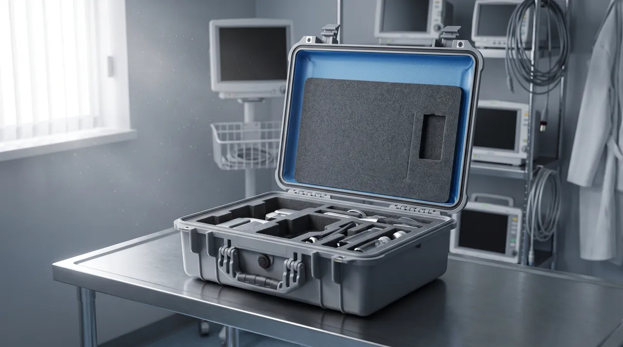
A kiln shell section is a thin-walled, large-diameter, long component. Deformation during transport comes from three directions: bending under self-weight, local indentation at supports, and radial out-of-roundness from stacking or strapping. The control measures differ substantially from ordinary equipment packaging.
The number and location of supports is the first variable. Too few supports and the section deflects visibly under its own weight, with long sections sagging at mid-span. Too many rigid supports and each one creates a local dent. Practice is to use uniformly distributed multi-point support, with spacing derived from wall thickness, diameter and material, verified by a simply supported beam approximation against an acceptable deflection limit.
Contour conformity of the support face is the second variable. Cradles should be arcs matched to the shell outside diameter, and the contact width should not be too narrow. When a hard support is unavoidable, add a soft facing that distributes pressure rather than being crushed through. For thin walls, high-density foam or engineered timber arc blocks are preferred, with a thin felt layer between block and shell where needed.
Restraint method is equally critical. A shell section must not be rigidly clamped, because temperature changes alter its dimensions and rigid clamping generates secondary stress. The correct approach is restraint without locking: arc cradles limit radial movement, flexible stops limit axial travel, and a small clearance is deliberately retained around the part. Straps need corner protection, and strap positions should align with internal stiffening rings so that concentrated force is not applied to unsupported wall.
Whether to fit temporary internal support rings is a technical and cost trade-off. For long sections with thin walls, removable internal rings are an effective measure that markedly improves resistance to out-of-roundness, but they add site removal work and occupy internal volume. For shorter sections, external multi-point arc support is normally sufficient.
Note also that the end bevel is a weld preparation face. Once struck or rusted, it must be re-ground on site, which affects fit-up accuracy. Protect the end face with a ring or cap and apply a removable rust-preventive compound to the internal end surface.
Load-Bearing Structure and Base Reinforcement for Large Cases
The core task of the load-bearing structure is to spread concentrated load as quickly as possible into the case frame and then into the transport vehicle. The design sequence is as follows.
Step one, define the load spectrum. This includes unit weight, total weight, centre-of-gravity position, lifting plan, stacking layers and the acceleration assumptions for the transport mode. Where the project requires distribution-cycle testing, use ASTM D4169 distribution cycle testing to establish the load levels.
Step two, select the base configuration. Three types are common: an integral steel pallet-type base frame, a hybrid timber and steel base, and an all-steel welded frame. Selection depends on unit weight, reuse count and whether forklift or crane handling is required.
Step three, orient the stiffeners. Stiffeners should follow the principal load direction and be densified under load concentration points. The connection between stiffener and panel governs overall stiffness, and the choice of welding or fasteners must survive fatigue from transport vibration.
Step four, design lifting and forklift interfaces. Lifting lug positions should align the sling direction with the case main beams; forklift pocket positions should keep the centre of gravity within the fork spread, and the insertion depth should be marked on the case.
Step five, provide stacking columns. If cases will be stacked, place through-columns at the four corners so that upper load travels directly to the ground rather than through the lid into the contents.
The following matrix gives a fast starting point at concept stage:
| Component type | Typical form | Load-bearing priority | Suggested base structure | Support form |
|---|---|---|---|---|
| --- | --- | --- | --- | --- |
| Support roller assembly | Concentrated heavy block | Local compression, bending | Integral steel base frame | Semicircular cradle plus reinforced base |
| Kiln shell section | Thin-walled long cylinder | Deflection and ovality | Steel saddle plus timber cradle | Multi-point arc support blocks |
| Tyre | Large diameter ring | Ovality and twisting | Flat reinforced base frame | Uniformly distributed multi-point support |
| Girth gear | Split arc segments | Distortion and tooth damage | Contour timber base frame | Tooth-face isolated support |
| Thrust roller and bearing shell | Small to medium precision | Fit surface protection | Multilayer foam liner | Contour cavity location |
On the manufacturing side, cases of this class are produced by Kexin New Materials (Guangdong) Co., Ltd., which can customise dimensions, base frames and liner arrangements to the project equipment train, offers OEM/ODM cooperation together with wholesale and agency distribution, and can deliver to major domestic and international ports and inland project sites. Where acceptance support is required, inspection reports and material certificates can be supplied under contract. For projects at concept stage that need to compare the cost implications of different structures, the method in custom protective case mould cost analysis is a useful reference.
Lifting Points, Centre-of-Gravity Marks and Out-of-Gauge Boundaries
Lifting incidents in kiln spare transport are not rare, and the root cause is usually not a wrong sling but case marking that does not reflect the true centre of gravity. A support roller assembly has uneven internal mass distribution, and a tyre is a ring body; if either is marked at its geometric centre, the load tilts noticeably or shifts once lifted.
The requirement is clear: confirm the centre-of-gravity position by calculation or measurement at concept stage and mark the symbol on two adjacent side walls; locate lifting lugs on the same vertical line as the centre-of-gravity projection or symmetrically about it; and where soft slings are used, state a recommended sling angle range, because a wide angle significantly increases both sling tension and lateral pressure on the case.
Out-of-gauge assessment and marking must also be addressed at concept stage. Cases exceeding normal dimensions or weight typically require permits and route planning against road conditions, and the case surface must show overall dimensions, total weight, centre of gravity and lifting points. Where a movement combines road and sea legs, marking should satisfy both modes so that transshipment handling is not misdirected.
For export projects, timber packaging materials must satisfy the international standard for phytosanitary measures covering wood packaging and carry the corresponding treatment mark. Load-bearing components in solid timber deserve particular attention, because they are large and cannot easily be substituted at short notice. Steel base frames are generally outside wood packaging quarantine scope, but the corrosion coating system must suit the marine environment.
A tip-over warning is also worth adding. Large rings and rollers depend on lashing for stability on the vehicle, and if the case is stacked on an upper layer the tip-over risk multiplies. Beyond lashing marks, the side wall can state that single-sided lifting is prohibited and that the lower layer's capacity must be confirmed before stacking.
Cradles and Liners: From Sleepers to Moulded High-Density Blocks
In this class of case the liner performs two duties: spreading load and restraining displacement. Sleepers, engineered timber blocks and moulded foam blocks are the three common means, each with distinct boundaries of use.
Sleepers and engineered timber cradles handle large concentrated loads well, cost little, machine easily and can be adjusted on site. Their weakness is poor conformality to irregular surfaces, which usually requires an added soft pad, and the moisture content and preservative treatment of the timber affect long-term service. Export projects must also consider quarantine requirements.
Moulded foam blocks, including high-density PE foam and EVA composites, suit arc cradles and locating cavities and conform well to surfaces of revolution while adding cushioning. Their weakness is creep under very high static load, so for tonne-level loads foam normally serves as a levelling and conforming layer while the main load path remains timber or steel.
Steel and timber composite cradles combine the load capacity of steel with the machinability of timber and are the usual choice for rollers and shell sections. A typical build is a welded steel arc cradle, an engineered timber pad on the supporting surface, and a thin soft pad between pad and component.
Three assembly details are commonly overlooked. First, there must be no hard point between liner and component; any metal-to-metal contact should be separated by a soft material. Second, the liner should be re-installable, because after overhaul the site often needs to repack the part into the same case, and a liner destroyed during unpacking cannot serve that purpose. Third, the liner should be marked with the corresponding item number and installation orientation so that cradles for different parts are not swapped.
For small and medium parts moved by two people, such as thrust rollers, bearing shells and fastener sets, the liner can be built as a pallet-type module that lifts out as a unit and travels straight to the installation point, reducing handling damage from a second manual transfer.
Rust and Moisture Control in Open Yards and Ocean Freight
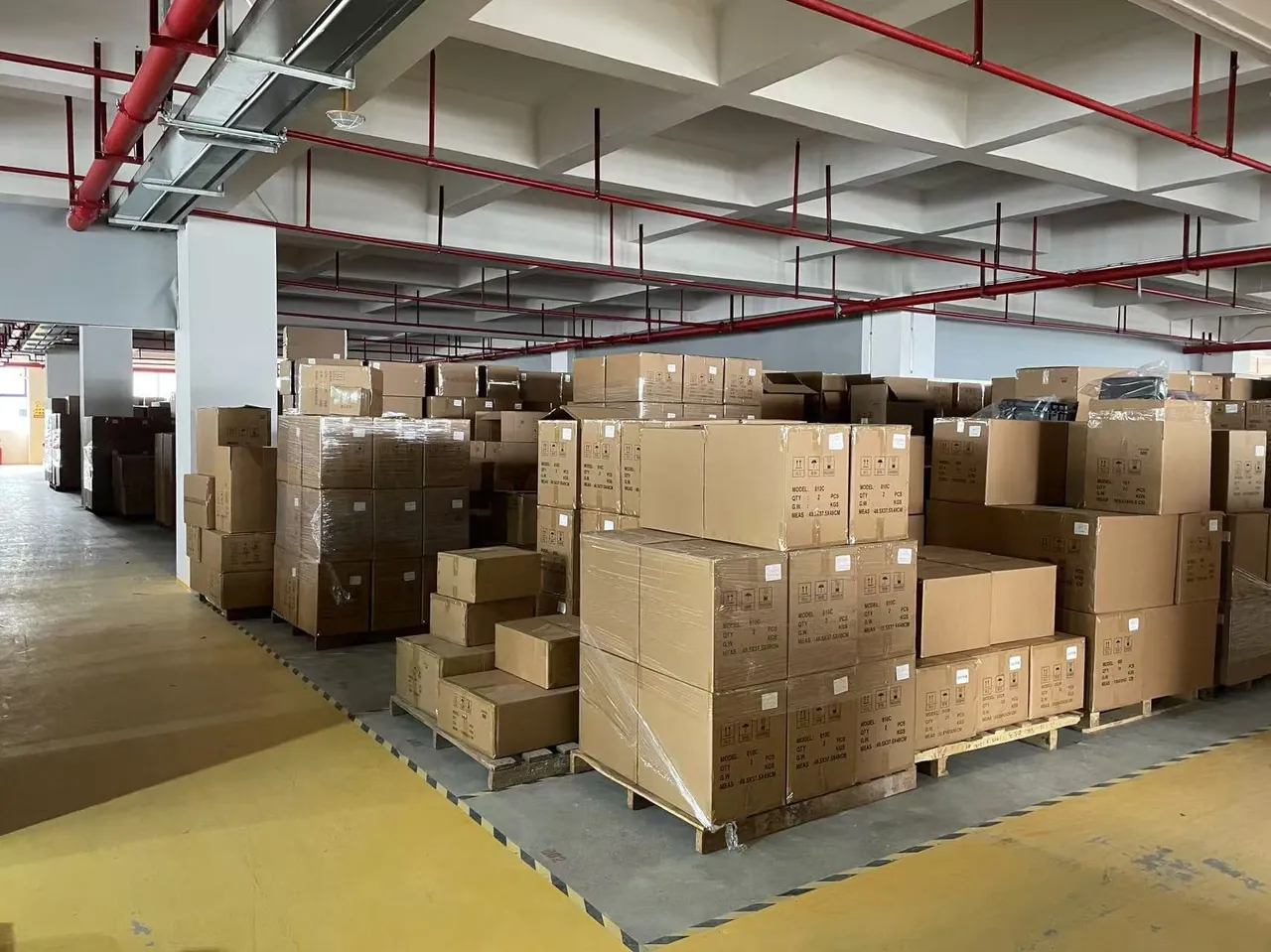
Storage conditions at a kiln project site are often harsher than the transport leg. Spares frequently sit in an open yard for weeks or months after arrival, exposed to day-night temperature swings, rainfall and ground damp. For machined surfaces, the cumulative effect over that period cannot be ignored.
Protection has three layers.
Layer one is surface preparation. Machined faces, bevels and journals should be coated with a removable rust-preventive compound before dispatch. The choice must anticipate downstream processes: weld areas should use a welding-compatible product so residues do not impair weld quality.
Layer two is barrier packaging. Wrap critical areas in vapour-phase corrosion inhibitor film or barrier film with a desiccant charge. Where a component is too large to wrap completely, at minimum apply a local barrier to the machined faces.
Layer three is case and yard management. The case itself should reach a protection level matched to the storage period, and the site should raise it off the ground, keep it clear of walls and prevent water pooling on top. The table below matches experience practice to storage duration:
| Storage period | Environment | Suggested case protection | Corrosion measures | Inspection frequency |
|---|---|---|---|---|
| --- | --- | --- | --- | --- |
| Under 1 month | Covered shed | Dust and splash class | Grease on critical faces | Once before unpacking |
| 1-3 months | Semi-open | Dust and splash plus dual gasket | Grease plus VCI film | Monthly |
| 3-6 months | Open, rainy | Immersion class plus breather valve | VCI film plus desiccant plus rain cover | Fortnightly |
| Over 6 months | Open, coastal | Immersion class plus barrier inner bag | Multilayer corrosion system | Weekly |
In high-salinity coastal projects, also consider the corrosivity of the packaging materials themselves. Sulphur- or chlorine-bearing papers and low-grade foams release corrosive species under damp conditions, so state material composition limits in the technical specification. For routine cleaning and care of the case body itself, see how to clean a protective case properly.
Sealing Systems, Breather Valves and Desiccant Sizing
The sealing architecture of a large case differs fundamentally from a small one: the larger the case, the greater the breathing volume caused by temperature cycling, and the longer the cumulative gasket length, so micro-leakage accumulates more noticeably. A small-case sealing scheme cannot simply be scaled up.
A three-level strategy is recommended.
At the gasket level, use a dual seal: the outer gasket blocks water and dust, the inner gasket provides airtightness. The gasket groove should be continuous without joints, and corners should be moulded rather than spliced. Inspect the sealing face after every closure for embedded grit.
At the pressure level, fit a pressure equalisation valve so the case equalises differential pressure through the valve rather than through gasket micro-gaps. This matters especially for large volumes, where the breathing quantity is proportionally large.
At the drying level, use metered desiccant with humidity indication. For large cases the charge should account not only for volume but also for moisture absorbed by liners and packaging materials and for water released by any refractory accessories. Distribute desiccant by hanging it in the upper internal volume, and either provide an inspection window or label the indicator card position externally.
Note that good sealing is conditional on cargo condition. If components carry grease and contaminants, a well-sealed case can trap volatiles that circulate internally and affect liners and cabling. Clean component surfaces before packing, and where necessary ventilate before final sealing. Gasket material tolerance and selection are covered in toolbox hinge and latch seal selection and in seal and shock case design essentials.
Transport Testing: Choosing Between GB/T 4857 and ASTM D4169
The purpose of transport testing is to verify whether a packaging scheme protects the goods along the actual logistics chain, not to pass a standard for its own sake. Method selection should therefore follow the logistics chain, not the reverse.
Three selection principles apply. First, match the method to the actual transport mode: road transport emphasises vibration and stacking, rail emphasises longitudinal shock, sea freight emphasises roll and stacking, and air freight emphasises pressure change and handling shock. Second, set severity from the worst leg, not from an average. Third, define acceptance criteria covering the permissible change in case structure, liner condition and component appearance after test.
The GB/T 4857 series stacking, vibration, impact and drop methods are widely used in domestic projects and correlate well with Chinese transport conditions. ASTM D4169 organises test sequences around a distribution cycle, which suits export projects with a defined logistics chain. Where a contract cites MIL-STD-810H, cite it as an environmental test method reference and note that it is not a military certification, while specifying the exact method number, severity level and acceptance criteria.
For very large or very heavy cases, a full drop test is often impractical. Alternatives include local structural load tests or simulation, testing a representative scaled item, or installing shock recorders on the first production shipment. Instrumenting the first shipment is often the best value verification available, because it captures real logistics data that can directly optimise liners and restraint for later batches.

Unpacking and Re-Inspection at the Site Staging Area
Kiln overhaul windows are tight, so site unpacking must complete inspection and confirmation within a limited time. The recommended flow is as follows.
Before opening: read the external humidity indication or inspection window result, record case appearance and stack position, and reconcile the case number against the equipment train list.
During opening: remove by zone, starting with the accessory and document zone, then light items, and finally heavy items. Lift heavy items using the marked lifting points, never using a machined face as a lifting point. Remove the liner intact and store it separately so it is not trampled or compressed.
After opening, confirm each item in the following table:
| Inspection object | Key check points | Judgement and action |
|---|---|---|
| --- | --- | --- |
| Case | Structural distortion, gasket wear, base corrosion | Distortion beyond limit means assess for scrapping |
| Support roller | Outer diameter scratches, journal rust, seal leakage | Journal rust requires fit assessment |
| Shell section | Ovality, end bevel, local indentation | Bevel damage requires on-site re-grinding |
| Tyre and girth gear | Ring ovality, tooth flank damage | Tooth damage judged against gear accuracy class |
| Liner | Collapse, displacement, debris | Displacement indicates insufficient restraint |
| Documentation | Packing list, liner layout, material certificates | Release to store only after completion |
Re-inspection and storage: reseal after inspection, top up the desiccant, renew sealing-face protection and manage according to the recommended storage conditions. If the overhaul is postponed, record the storage start and end dates and environmental data during the period, so that any decision to re-apply corrosion protection rests on evidence. For design life and replacement criteria, see protective case service life and replacement.
Project Supply Packages and OEM Cooperation Models
Kiln projects are usually procured by equipment train, and a single project contains both large and small items, so packaging must be planned as a whole rather than assembled piece by piece. A five-step workflow is recommended.
Step one, receive project data. This includes the equipment list, component dimensions and weights, centre-of-gravity data, transport mode and route, storage duration and destination climate.
Step two, issue the solution. State which items share a case and which must ship separately, and for each case define protection level, load-bearing structure, liner form, sealing and drying scheme, and the marking and documentation list.
Step three, verify the first article. Build a representative first article and run loading verification, transport testing where needed, or install shock recorders.
Step four, volume production. Produce by project equipment-train number with traceable records, and support phased delivery to match the overhaul window.
Step five, site support. Provide liner repacking drawings, storage advice and on-site unpacking guidance.
On cooperation models, cases of this class are manufactured by Kexin New Materials (Guangdong) Co., Ltd., which customises case dimensions, load-bearing base frames and liners to project requirements, supports OEM/ODM cooperation together with wholesale and agency channels, and covers major domestic and international ports and inland industrial sites. Where acceptance applies, the relevant inspection and material documents can be provided under contract. For contractors running several projects in parallel, it is worth converging case specifications into a family series to cut tooling and changeover cost, consistent with the supplier assessment dimensions set out in how to choose a protective case OEM factory.
Out-of-Gauge Compliance, Marking and Shipping Documents
Out-of-gauge compliance is the stage most often overlooked, yet it affects project milestones directly. Key considerations include route permits and bridge and culvert load assessment, night-time and speed restrictions, vehicle signage and warning lights, and confirmation of lifting capacity at the unloading point. These should be agreed with the carrier at concept stage, because once case dimensions are frozen, later changes are expensive.
Recommended shipping documents include the packing list with item number, description, quantity, material and unit weight; liner layout drawings and repacking instructions; a load-bearing and lifting statement including the centre-of-gravity and lifting-point diagram; the corrosion treatment description with validity period; the desiccant dosing record and humidity indication note; copies of material and inspection documents; and evidence of wood packaging treatment marking.
If electrical accessories are included, such as thermocouples or limit switches, provide a separate protection note specifying moisture control and insulation checks. These items are small, yet a missing spare at site frequently causes downtime far out of proportion to its size and cost.
Frequently Asked Questions
Q: Can a rotary kiln support roller assembly be shipped in an ordinary foam-lined protective case?
A: Generally not advisable. A support roller assembly is a tonne-level concentrated load, and ordinary foam liners lack the compressive capacity and creep resistance required. Over an extended static period the foam compresses permanently, the roller settles inside the case and contacts the base or a neighbouring component, and the intended restraint is lost without any visible external damage. The workable arrangement is for a steel or steel-timber composite base frame to carry the main load, with foam acting only as a levelling and conforming layer whose thickness and density are selected against both the static load and the cushioning requirement. The roller outer diameter is also a fit surface, so support should use a matching semicircular cradle that spreads contact stress over a controlled wrap angle rather than letting the diameter rest on a hard flat surface or against a steel edge. Before packing, confirm that grease cannot bleed and contaminate the liner or adjacent parts, adding an oil guard where necessary, and verify the final arrangement through loading verification or transport testing before volume production.
Q: If a kiln shell section deforms in transit, can it still be used?
A: It depends on the magnitude and location, and the answer must come from measurement rather than visual inspection. Shell ovality and straightness directly affect the kiln centreline and the girth gear mesh, and out-of-tolerance values cause running vibration, uneven tyre contact and accelerated gear wear. On site, measure diameter and roundness at several sections with suitable instruments and check specifically for local indentation near support points, because that pattern indicates over-constrained support rather than general overload. If deformation stayed within the elastic range, much of it will recover once restraint is released, but recovery is not guaranteed and must be confirmed by re-measurement after a settling period. Local plastic indentation or end bevel damage normally requires on-site correction and re-grinding, which affects fit-up accuracy and the assembly schedule. Prevention is far more valuable than cure: multi-point uniform arc support, no rigid clamping, and strap positions aligned with internal stiffening rings together remove most of the risk.
Q: How should the protection level for large kiln spare cases be determined?
A: Not by choosing the highest available, but by matching the actual logistics chain and storage duration. If spares move domestically by full truckload and are installed on arrival, dust and splash protection plus corrosion treatment of critical faces is entirely sufficient, and specifying more simply adds cost and tare weight. If they travel by sea and then sit in an open yard for months, the combination of immersion-class protection, dual gaskets, a pressure equalisation valve and a barrier inner bag is needed, together with metered desiccant and humidity indication. Note in particular that larger cases breathe more under temperature cycling and accumulate more moisture through gasket micro-gaps, so large cases generally demand stricter pressure equalisation and drying measures than small ones, not merely thicker walls. Write the protection level, desiccant charge and humidity indication requirements into the technical specification as measurable items, and put the intended storage duration into the site work instruction so goods are not left unmanaged after arrival.
Q: How early should out-of-gauge transport be brought into the packaging design?
A: As early as possible, ideally while the equipment concept is being fixed and before case dimensions are frozen. Once the case outline and weight are settled, the transport permit, route selection, bridge and culvert load assessment, vehicle signage and unloading-point lifting capacity all need to be matched to them, and the lead time for those activities often exceeds that of the packaging itself. The common reactive situation is a case already manufactured, only then discovering that a route segment is impassable, that a permitted corridor has restricted hours, or that the delivery point lacks sufficient crane capacity, forcing transloading that raises both cost and exposure to damage. Agree the dimensional limit, weight limit and lifting scheme with the carrier at concept stage, record the conclusions in the transport plan, and freeze them into the case drawings so that later packaging changes do not invalidate the transport approval. Treat the transport study as an input to the packaging design rather than a downstream consequence of it.
Q: Why is rigid clamping not recommended for large rings and shell sections?
A: Because rigid clamping converts relative movement during transport into secondary stress, and large bodies of revolution are comparatively sensitive to it. Shell sections and tyres are thin relative to their diameter, so a local clamp produces radial deformation concentrated near the clamp point, which is exactly the distortion the case is meant to prevent. Metal components also change dimension with temperature, and a rigid restraint opposes that change, creating cyclic stress over a long voyage with large day-night swings. A better approach is restraint without locking: arc cradles matching the contour limit radial movement, flexible stops limit axial travel, and slight movement is permitted while impact is prevented. Straps should have corner protection and should align with internal stiffening rings or ribs wherever possible, so that force is not applied to unsupported wall. This controls displacement in transit while avoiding difficult and potentially damaging removal on site. Where a part is unavoidably sensitive to movement, solve the problem with geometry and compliant pads rather than with greater clamping force.
Q: How should vapour-phase corrosion inhibitor film and ordinary barrier film be chosen?
A: They serve different purposes and are normally combined rather than selected between. Barrier film aims to reduce water vapour transmission rate, keeping external moisture outside the package. VCI film aims to release corrosion-inhibiting compounds within an enclosed space and form a protective layer on metal surfaces, suppressing corrosion caused by the small amount of moisture and oxygen that has already entered, which barrier film alone cannot neutralise. For machined faces, bevels and journals, the recommended build is a removable rust-preventive compound first, then VCI film wrapping, then an outer barrier film with a desiccant charge. Note two constraints. VCI material selection must anticipate downstream processes, so weld areas should use welding-compatible products whose residues will not impair weld quality. The inhibitor must also be confirmed compatible with the component surface coating and with gasket materials, to avoid swelling or discolouration that would only be discovered at assembly. Keep a sample of the chosen materials with the project file so future batches can be verified against it.
Q: What additional measures are needed if spares are stored on site for more than six months?
A: Six months is a point that warrants formal re-assessment rather than routine inspection. A four-step response is suggested. First, re-confirm case sealing condition and humidity indication, replace the desiccant as needed and reseal the case properly. Second, sample the corrosion state of critical machined faces, and if early rust bloom appears, clean and re-apply immediately rather than waiting for the layer to deepen, because surface bloom is far cheaper to remove than pitting. Third, check the liner for collapse or displacement, particularly beneath heavy components, since foam materials creep under long-term static load and the settling may be invisible from outside. Fourth, review the storage environment, focusing on ground damp, standing water on the lid and actual stacking pressure against the marked limit. In high-salinity coastal locations, raise inspection frequency and confirm packaging materials are free of sulphur, chlorine and acidic substances. Retain all records as evidence for acceptance and traceability.
Q: Should large and small components in the same project share one case type?
A: Forced standardisation is not recommended, but specification family convergence is. Large and small components differ markedly in load bearing, protection level and handling method, so forcing one type leads to over-design for small items and insufficient capacity for large ones, with the added penalty that the heavy case becomes expensive and awkward to handle. A better approach divides cases into a limited number of families by load band and size band, with structure and sealing shared within a family and only dimensions and liners adjusted for individual parts. This preserves case-by-case fitness while amortising tooling and production changeover cost across the project. For contractors there is a further operational benefit: common disassembly tooling across the project, interchangeable liner spares, and stacking dimensions that match one another on site. When defining the families, also consider the dimensional modules of the transport vehicles actually available, so that impractical sizes never reach the drawing stage.
Q: Why is a liner repacking drawing emphasised in the delivery documents?
A: Because after a kiln overhaul the removed or spare parts often need to be repacked into the same case for storage or return, and if the liner was taken out during unpacking but cannot be reinstalled correctly, the case loses most of its protective capability for the remainder of its service life. A repacking drawing tells site personnel exactly where each cradle and foam layer belongs and in which orientation, preventing misassembly that would change the load path on the component. For load-bearing liners the consequence of misassembly is more serious, potentially leaving a heavy component under-supported and distorting it during storage. Map the repacking drawing to item numbers one to one, mark item number and orientation on the liner bodies themselves, and for complex multilayer builds keep a photograph of the standard packed state inside the case as a direct visual reference for the team on shift. Review the drawing whenever a liner design changes, so it never describes a configuration that no longer exists.
Conclusion and Related Reading
The design logic for rotary kiln component cases condenses into three statements: load before volume, distribution before fixation, verification before volume production. Calculate unit weight and centre of gravity first and derive the load-bearing structure from them; then spread load and restrain movement through multi-point, area-contact and compliant restraint; then confirm the scheme through loading verification, transport testing or first-article measurement before committing to production. Get those three right and the roller fit faces, shell ovality and tyre roundness will still be in as-dispatched condition at the moment of unpacking.
Related Reading