

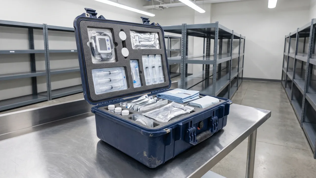
In warehousing and unitized transport, protective cases rarely exist as single units; for most of their service life they are stored and moved in stacks of several to more than ten layers. Insufficient stacking strength or improper stacking practice is the leading cause of case deformation, cracking and even stack collapse in the warehouse phase, and the resulting losses usually far exceed the value of the cases themselves. This article covers the load principles behind stacking, structural design elements, the test standard system, layer count calculation and on-site stacking operation rules. It is written for warehousing and logistics units, unitized transport planners and OEM structural verification engineers. The stacking capability of a protective case cannot be summarized by a single sentence such as "it can stack eight high"; it is jointly determined by static load, dynamic load and creep, and is significantly affected by temperature, humidity and storage duration. Only by understanding the coupling between these variables can stacking be turned from an empirical habit into a controlled engineering process.
1. Scope and Basic Concepts of Stacking Rules
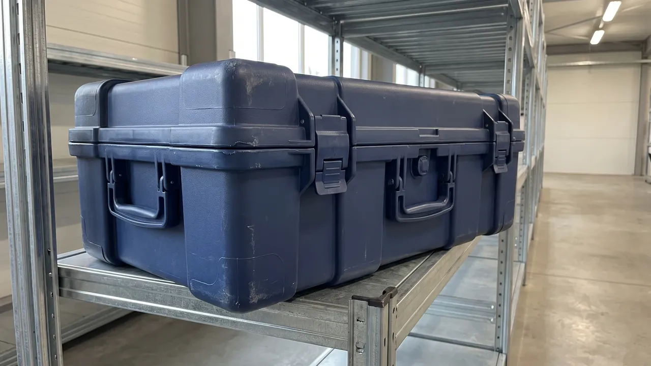
Stacking rules apply to all scenarios in which a protective case bears vertically superimposed loads during static storage, in-warehouse transfer, palletizing and road or sea transport. Three basic concepts must be clarified first. Stacking load is the total weight of the upper cases pressing on the top of a lower case. Stacking strength is the ability of the case to resist that load under specified conditions without harmful deformation or failure. Permissible stacking height is the actual number of layers allowed under the combined constraints of strength, stability and operational safety. These three form a closed loop of "load, capability, limit", and a missing link in any of them leaves the stack uncontrolled. It should be noted that stacking capability is an attribute of the container itself, while stack stability also depends on floor flatness, pallet stiffness and alignment quality, and the two must not be confused. A common problem in practice is that procurement only asks "how many layers can it stack" without agreeing on test conditions and load definitions, so that stacking according to the buyer's own working conditions immediately causes sagging or bulging after delivery. The starting point of any standard is to convert "how many layers" back into "how many layers under what temperature, what duration and how many kilonewtons", and to state each item in the contract and acceptance documents. For the fundamentals of load-bearing structure design, refer to the Case Stacking Structure article.
2. Load Principles: Static Load, Dynamic Load and Creep
The loads borne by a protective case in a stack fall into three categories. Static load is the constant pressure a case bears during long-term stationary stacking; it acts for a long time at a stable magnitude and tests the long-term load capacity of the material. Dynamic load comes from bumps, braking and vibration during transport; vertical acceleration can make the instantaneous load far exceed the static value, and the vertical impact factor for rail and road transport is usually estimated at 1.5 to 2 times gravity based on experience, while wave slamming at sea can be higher still. Creep is the phenomenon whereby the strain of polymeric materials continues to grow over time under constant stress. Plastic protective cases are particularly sensitive in this respect: a case with high short-term compressive strength may slowly bow and bulge under long-term full stacking, and after several months the deformation may exceed assembly tolerances. The three load types follow completely different evaluation logics: static load is judged against the creep limit, dynamic load against the impact margin, and long-term storage against the creep reduction. Selection and design must therefore identify the dominant working condition first. If the cases mostly sit statically on warehouse racks for months, creep performance is the primary indicator; if they are frequently transported by vehicle, structural margin under dynamic load and latch strength carry more weight. Evaluating the three load types separately and then taking the envelope is the basic methodology for determining stacking capability.
3. Stacking Strength Design: Structure and Load Path
The essence of stacking strength is to let the top load travel to the ground along a continuous, low-stress and predictable path. Design should first consider the integrity of the load path: the load should pass in sequence through the top load-bearing zone, the side wall ribs, the corner columns and the bottom load frame, and any break in this chain forces the load to detour, concentrating stress at weak points. Injection molded cases usually rely on built-in vertical rib grids to form the load-bearing skeleton, while rotomolded cases depend on double-wall structures and embedded reinforcements. Three points deserve close attention during design review. First, whether a straight column path exists between the top cover and the corners, so that the load does not squeeze the side walls laterally. Second, whether the bottom load frame aligns with the pallet fork openings, preventing local bridging and bending during fork handling. Third, whether openings for handles, latches and valves are placed outside the load-bearing zone; if they cannot be avoided, reinforcing rings are required. Wall thickness determination should proceed together with the load path; simply thickening the whole shell to improve stacking is neither economical nor always effective, and the quantitative relationship can be found in the article on Case Wall Thickness Strength. After the load path design is complete, a structural check under stacking conditions is recommended, comparing the maximum stress point against the allowable value of the material with sufficient margin before mold opening.
4. Function of Ribs, Corners and the Bottom Load Frame
Ribs are the most economical means for a plastic case to gain stacking stiffness. Vertically continuous ribs divide a large thin wall into small cells and markedly raise the bending section modulus; their effect grows roughly with the cube of rib height, so a layout of "tall and sparse" ribs usually outperforms "short and dense". Excessive rib height, however, brings sink marks and internal stress problems and must be coordinated with the molding process. The corners are the key load transfer nodes in a stack: the four corners carry most of the vertical load, and the material thickness, fillet radius and internal structure at the corners determine the stacking ceiling of the whole case. Case models with corner load columns or metal inserts usually show clearly better stacking performance, and details can be found in the Case Stacking Corner Guide. The bottom load frame is the outlet of the load and determines whether the case achieves "line bearing" or "area bearing" on the pallet. Area bearing places low demands on pallet flatness and distributes the load evenly but consumes more material; line bearing saves material but is sensitive to pallet deflection and must match the pallet structure. The three elements should be designed together: rib layout, corner structure and bottom frame form jointly constitute the load-bearing system, and optimizing any one of them in isolation may merely move the weak point elsewhere. In OEM customization projects, the load-bearing structure should be designed specifically for the customer's maximum storage layers and storage duration rather than directly reusing a general-purpose mold.
5. Stacking Test Methods and the Standard System
The evaluation of stacking performance has a mature test standard system, and buyers should require suppliers to issue reports to these standards instead of verbal promises. In China the GB/T 4857 series is most commonly used: the static stacking test specifies the deformation and failure criteria under a constant load acting for a long period, and the compression test provides the compressive strength and displacement curve; the methods are interpreted in the GB/T 4857 Transport Packaging article. Internationally, ISO 2234 specifies the static load stacking test method for complete, filled transport packages, ASTM D642 measures the compressive resistance of shipping containers and components, and the ISTA series integrates stacking into full distribution simulation; for example, ISTA 3E for unitized loads includes a stack persistence element, while ASTM D4169 combines stacking, vibration and drop into a sequence test according to the distribution cycle, as explained in the ASTM D4169 Distribution Cycle article. When selecting standards, pay attention to the mapping between test conditions and real working conditions: the load value should be converted from the expected maximum number of layers plus a safety factor, the test duration should cover the longest storage period, and loaded condition with liners is closer to reality. Acceptance documents should state four elements: the standard number, the load, the temperature and the acceptance criteria; a report missing any of them should be regarded as non-acceptable.
6. Maximum Stack Layer Calculation and Safety Factor
The number of stacking layers is not guessed but is an engineering quantity that can be calculated and then verified by testing. The basic procedure has four steps. Step one: determine or obtain the single-case compressive strength, that is, the force at which the case reaches the defined deformation limit in a standard compression test, recorded as the critical load. Step two: calculate the effective load per layer: the weight of one loaded case multiplied by the actual number of layers above, plus a load distribution non-uniformity factor; the four corners of each case never share the load perfectly, and an unevenness factor of 1.1 to 1.3 is common in engineering. Step three: apply the safety factor and reduction terms: the safety factor is generally taken as 3 to 5 depending on storage duration and failure consequence; for plastic cases a creep reduction is added on top, and a common practice is to multiply the critical load by an empirical factor of 0.4 to 0.6 before comparing with the total load. Step four: close the loop with testing: run a loaded stacking verification according to the calculation and confirm that the deformation after long-term stacking stays within the allowed range. As an example, if the single-case critical compressive value is 20 kN, the creep-reduced value is 10 kN and the safety factor is 4, the allowable load is 2.5 kN; if each loaded case weighs 15 kg, the theoretical ceiling is over ten layers, and the actual layer count is then determined together with height limits and operational safety requirements. Calculation is only the starting point; the final permissible layer count must be supported by long-term stacking tests or historical data from comparable products.
7. Creep Reduction and Strength Decay in Long-Term Stacking
Creep is the most underestimated factor in plastic case stacking management. Under constant stress, thermoplastic materials show strain that keeps growing with time: growth is fast at the beginning, then enters a steady stage, and accelerates again as failure approaches. For stacking, the direct consequence of creep is outward bulging of the side walls, sinking of the top cover and misalignment between layers, and in severe cases the upper cases slide off. Creep performance is strongly temperature dependent; each increment of temperature multiplies the creep rate, so the risk of stacks in the top zone of a hot warehouse in summer is significantly higher than at room temperature, and humidity has a similar accelerating effect on hygroscopic materials such as nylon. The engineering countermeasures operate on three levels. First, at the design stage, select materials using creep curves, prefer high-crystallinity creep-resistant grades, and use creep strength rather than short-term strength as the basis of allowable stress. Second, in storage management, apply time-limited stacking and periodic destacking to release stress, keeping the continuous full-load stacking period within the range assumed by the creep reduction. Third, for monitoring, set deformation observation points at the top and waist of the stack, measure the layer height regularly, and trigger destacking once the change exceeds the trend line. For projects with storage periods longer than several months, it is recommended to require creep reduction statements or sustained load test data from the supplier at ordering time; JUNZHIJIA provides the corresponding stacking and endurance test documents with its custom load-bearing structure projects so that customers can use them directly as acceptance evidence. Creep assessment should also be synchronized with the micro-environment management described in Warehouse Stacking Moisture Cases, to avoid the coupled acceleration of strength decay in humid and hot conditions.

8. On-Site Stacking Rules: Heavy Below, Alignment and Height Limits
Possessing cases with adequate load capacity does not automatically produce a safe stack. On-site operation rules should include at least four items. First, heavy cases below and light cases above: the weight difference between adjacent layers should not be excessive, to avoid both a raised center of gravity and overload of the lower layer. Second, aligned placement: the edges of upper and lower cases should be aligned, with deviation controlled within 5 percent of the case base dimension; misaligned placement makes the load pass diagonally through the case walls, creating eccentric compression, which is the most common trigger of stack collapse. Third, height limit management: the permissible layer count takes the minimum of the "strength calculation layer count", the "operational safety layer count" and the "warehouse clear height layer count"; in-warehouse stacks should also respect fire lane and sprinkler clearance requirements, and a stack height within 4 meters for mechanical handling environments and within 2.5 meters for manual stacking are common empirical values. Fourth, aisles and gaps: reserve inspection and ventilation gaps between stacks and between stacks and walls, so that deformation and tilt trends can be observed during patrols. Every rule should be written into the warehouse work instructions and included in training assessments, with height limit and layer count signs posted in the stacking area. Enforcement is harder than drafting; it is recommended to put layer height, alignment and stack geometry deviations into the warehouse inspection checklist, replacing visual impressions with data. The complete in-warehouse storage rules can be found in the Case Warehouse Storage Rules.
9. Pallet Matching and Stacking Points in Unitized Transport
Unitized transport of protective cases takes the pallet as the basic unit, and stack quality is largely decided by the pallet. The first item is pallet stiffness: a flexible pallet deflects noticeably under full load, making the case bottom designed for line bearing become bridged loading, which can multiply the stress; therefore matching the pallet to the case bottom load frame is the first step of a unitization plan, as detailed in Case Stackability Pallet Planning. The second is unit stacking on the pallet: cases should not overhang the pallet edge, because overhang causes shear on the case corners during fork handling; corner protectors and stretch wrap should be added on top of the unit to prevent individual case displacement during transport. The third is stacking between units: if one pallet unit is stacked on another, both the pallet capacity and the case stacking capability must be checked, and a load-spreading board should be placed between the two units. The fourth is vehicle securing: the horizontal inertia forces generated by braking and cornering far exceed common intuition; fully loaded pallets should be secured with straps, anti-slip mats or anchor points in the van body, and under dynamic load the vertical direction should also be rechecked by adding the impact factor to the case stacking margin. The unitization plan should be validated as a whole in a distribution cycle test rather than validating the case and the pallet separately. At the planning stage it is recommended to draw a load transfer diagram listing every load-bearing interface from the topmost case down to the ground, and any interface that fails means the whole plan is downgraded.
10. Influence of Temperature and Humidity on Stacking Performance
Temperature and humidity rewrite stacking capability indirectly through material properties, which is why environmental clauses belong in stacking rules. On the high-temperature side, the modulus of most engineering plastics falls as temperature rises; in open-air or non-air-conditioned warehouses in summer, the actual compressive capacity of a case can be clearly lower than the nominal room-temperature value, and the layer count should be reduced for the hot condition. If the stack top receives direct sunlight, the local temperature rise further accelerates creep and aging. On the low-temperature side, materials become brittle and impact resistance drops; static stacking itself is not the problem, but knocks during handling more easily cause cracking, so cold storage and northern winter yards should use low-temperature resistant grades and slow down the operation tempo. On the humidity side, hygroscopic materials lose strength and stiffness, and the humid-hot environment promotes stress relaxation, making long-term stacking deformation appear sooner; if the cases contain moisture-sensitive equipment, condensation protection must be considered as well. Ground conditions are equally critical: uneven floors cause severe load imbalance among the cases in the bottom layer, with individual cases carrying several times the average load, and soft wet ground can also sink the pallets and tilt the stack. The standard practice is to establish an environment archive by season and warehouse zone, writing the summer reduction and the winter operation requirements separately into the stacking parameter table instead of applying one layer count all year round. For stacking projects sensitive to temperature and humidity, the environmental monitoring records should be kept as annexes to the stacking acceptance, forming a traceable evidence chain.
11. Stacking Accessories: Anti-Slip Mats, Locating Cones and Layer Boards
Well-chosen stacking accessories upgrade stacking from "placement by feel" to "positioning by structure". The anti-slip mat is the most common accessory, placed between the case bottom and the pallet or the top of the lower case; through high-friction material it blocks horizontal sliding and is remarkably effective in vehicle transport and slightly sloped floor situations. Selection points are described in Case Antislip Feet. Locating cones or pins provide mechanical alignment between layers: the upper case bottom has conical holes or locating grooves, the lower case top has matching cones, and the cases self-align when placed, eliminating misalignment at the root. This is especially suitable for automated warehouses and robotic palletizing scenarios. Layer boards solve two problems: when the top bearing surfaces of the upper and lower cases are not flat, a board spreads the load evenly; and when different case models are mixed in one stack, boards avoid point crushing. In addition, corner protectors, stretch wrap and strapping belong to the stack fixing group of accessories, used to suppress lateral sway of the stack during transport. Accessory configuration should match the case model: models with locating structures do not need anti-slip mats again, while mixed stacks must have layer boards. A checking and replacement system for accessories should also be established, because aged and cracked mats and worn cones are hazard sources. In terms of return on investment, stacking accessories cost little compared with the cases, yet their suppression of collapse risk is considerable, so they are recommended as standard budget items in unitization plans.
12. Failure Modes and Typical Cases
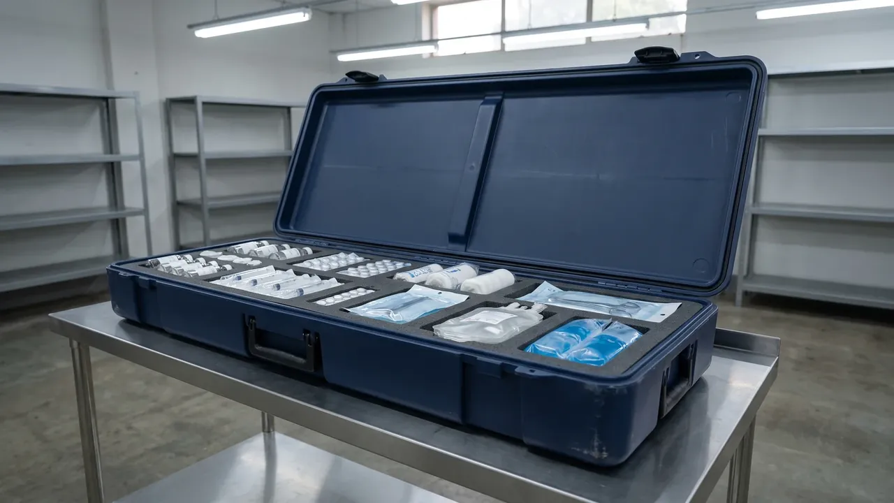
Stacking failures can be grouped into several typical modes. The first is case crushing: sinking of the top cover, bulging of side walls or cracking at the corners, usually because the permissible layer count exceeded the strength capability or the creep reduction was insufficient, commonly seen in long-term full stacking in hot warehouse zones. The second is stack instability and tipping: individual case strength is fine, but misaligned placement, uneven floors or a high center of gravity make the whole stack drift sideways, mostly occurring in fast manual stacking without locating structures. The third is slip and scatter: transport vibration weakens the interlayer friction and the stack shifts layer by layer until it scatters, mostly seen in vehicle transport without strapping and anti-slip measures. The fourth is local indentation damage: a foreign object left on a case top, or a handle protruding from the case below, creates point crushing; although rarely fatal, it damages the equipment and the sealing surfaces. Reviewing typical cases extracts common lessons. One organization mixed empty and loaded cases in one stack; the empty cases deformed under pressure and jammed so tightly that they had to be destroyed to be removed. Another batch was stacked according to the room-temperature report in a hot warehouse, and after three months the side walls bulged beyond tolerance and the whole batch was scrapped. The common point of these cases is the disconnection between test conditions and use conditions. The safeguards rest on three practices: verify the consistency between test conditions and your own working conditions before acceptance; perform patrols and deformation monitoring during storage; and after an anomaly, stop and assess the stack before any handling, never continue stacking with a damaged pile. Every failure should produce a written analysis that feeds back into the stacking parameter table, letting the rules evolve with the lessons.
13. Acceptance, Re-Verification and Record Management
The closed loop of stacking management lies in acceptance and continuous re-verification. At acceptance, four groups of documents should be checked: the stacking test report with its standard number, load and temperature conditions; the creep reduction or sustained storage statement; the verification records under loaded condition with liners; and the correspondence with the contractual layer clauses. For physical sampling, a static stacking spot check can be performed: stack the cases fully loaded at the contractual layer count for the specified duration and then measure the layer height change and case deformation to judge whether they remain within the allowed range. For re-verification, the stacking capability of plastic cases decays with service years and stacking history, so an annual or cumulative-hours based sampling is recommended, focusing on hot warehouse zones and overdue stacks. Record management solidifies these activities: each stack gets a storage card recording the placement date, layer count, case batch and responsible person; every destacking, patrol and anomaly disposal is logged; and due re-verification triggers automatic reminders. For OEM and volume procurement projects, re-verification rights and non-conforming disposition clauses should be agreed in the contract; JUNZHIJIA can provide stacking parameter tables and test documents by model for unitized transport and warehousing customers, helping them establish the first acceptance baseline. After three years or more of record accumulation, the data can also optimize procurement specifications in reverse: which case models never showed stacking anomalies and which zones alarm year after year become obvious at a glance. The value of stacking rules lies not in the documents themselves but in ensuring that every placement is traceable and every adjustment is data based.
FAQ
Q: Is the stacking layer count of a protective case just a manufacturer label? How should it be verified? A: The stacking layer count must be based on test data and should not be accepted on the manufacturer's label alone. Verification takes three steps. First, require the supplier to issue a stacking test report executed to a recognized standard, stating the test load, temperature, duration and acceptance criteria; a verbal promise of "ten layers" has no acceptance value. Second, check the mapping between the test conditions and your own working conditions; for example, if the report is a room-temperature short-duration test while your warehouse zone is hot in summer and requires half a year of storage, there is a risk of insufficient creep reduction. Third, where conditions allow, perform an incoming spot check by stacking at the contractual layer count under load and observing the deformation. The procurement contract should also define the load definition and the re-verification right, turning the layer count from a promotional figure into an enforceable contractual clause, which is the most effective way to prevent stacking disputes.
Q: Will a plastic protective case be crushed more and more under long-term stacking? How serious is creep? A: Thermoplastics do exhibit creep, meaning deformation continues to grow with time under constant stress, but progressive collapse is not inevitable; the key is whether the design leaves margin for creep. Proper products include creep reduction in the allowable load, that is, using a value far below the short-term compressive strength as the permissible value for long-term storage, with an empirical reduction commonly taken at 40 to 60 percent of the short-term strength. Used according to this principle, long-term stacking only produces a small amount of controllable elastic and creep deformation and does not keep worsening. The risk mainly appears in three situations: the layer count was derived from short-term strength without reduction; the storage temperature is significantly higher than the test temperature; or the continuous full-load storage exceeds the design period. In management terms, time-limited stacking and periodic destacking are recommended, together with deformation observation points on the stack; once the layer height change accelerates, disposal is triggered, which keeps the creep risk within an engineering-acceptable range.
Q: Can empty cases and loaded cases be stacked together? A: In principle, empty cases and fully loaded cases should not be mixed in one stack, and loaded cases must never press on empty ones. An empty case has thin walls and no internal support, so under the load from above its side walls and top cover easily dent inward; in mild cases the deformation exceeds tolerance and affects later loading and closing, in severe cases the case is crushed, and it may even jam in the stack so tightly that it must be destroyed to be removed. If site pressure truly requires mixing, three disciplines apply: empty cases only in the top layer, within the layer count corresponding to their own allowable load; empty cases fitted with internal supports or nested and locked together to improve deformation resistance; and layer boards between levels to spread the load so that the corners of loaded cases do not press pointwise on empty case tops. A better practice is separate zoning: store empty cases together in an upright or nested mode, which saves space and removes the compression risk at the same time. Deformation caused by mixed stacking is a typical human failure that can be avoided completely through placement rules at zero cost.
Q: How large is the influence of an uneven warehouse floor on a protective case stack? A: The influence is far more serious than most people expect. An uneven floor causes severe load imbalance among the bottom-layer cases, and an individual case may carry several times the average load, so even if the total stack weight is well below the design allowable value, a local case can crush or crack first and trigger chain instability. A more hidden problem is warping load: when a bottom case rests on three points with one suspended, its base stays in a bending state for a long time, and the stress far exceeds the uniformly distributed compression condition, so creep deformation accumulates faster. Countermeasures include using flat concrete floors in stacking zones and checking settlement regularly; using pallets as the load-equalizing layer and choosing double-face pallets with sufficient stiffness; marking depressed floor areas as forbidden; and preferring cases with a bottom load frame for the first layer. For existing uneven zones, leveling boards can be placed under the pallets, and the patrol frequency on stack verticality should be increased; once a tilt trend is found, the stack should be dismantled and rebuilt immediately.
Q: Should the stacking layer count be reduced in a hot warehouse in summer? A: Yes. The strength and stiffness of most engineering plastics fall as temperature rises, and the creep rate multiplies, so the actual stacking capability in a hot warehouse zone in summer is lower than the nominal room-temperature value. The engineering approach is a seasonal reduction: if the nominal layer count is based on room-temperature tests, a hot zone is advised to run at 0.6 to 0.8 of the nominal value, with the exact factor determined from the high-temperature performance data of the material rather than guessed. Attention should also be paid to stack position: stay away from roof heat radiation zones and beneath skylights, and prefer low-level racks or the cooler parts of the building; if the stack top receives direct sunlight, the local temperature rise further weakens strength. Constant-temperature warehouses may keep the original nominal values. Writing the seasonal reduction into the stacking parameter table, switching the executed layer count by season and having the warehouse staff verify stack by stack at each season change is the minimum-cost way to manage the environmental factor.
Q: Do anti-slip mats, locating cones and layer boards all need to be equipped? A: Not all of them; configure according to the working condition. Anti-slip mats suit scenarios with horizontal sliding risk: vehicle transport, slightly sloped floors and zones with frequent forklift bumps; their main role is suppressing interlayer slip. Purely static rack storage on a level floor can go without them. Locating cones suit scenarios demanding high placement accuracy: automated warehouses, robotic palletizing, or manual zones where fast stacking easily misaligns; they shift the alignment duty from people to structure and are the most reliable misalignment prevention. Layer boards are mandatory in two situations: different case models mixed in one stack, or uneven top bearing surfaces that need load spreading. The selection principle is to reason backward from the failure mode: use mats against slip, cones against misalignment, boards against point crushing. It is recommended to list the loads and environments faced by the stack during the unitization plan review and match the accessories item by item, spending the accessory budget on real risk points.
Q: Why do cases still get crushed in actual use despite the data in the stacking test report? A: The gap between report data and field failure usually comes from four links. First, missing condition mapping: the report may be a room-temperature, empty-case, short-duration test, while the reality is hot, loaded and long-term; each difference consumes part of the margin, and the sum can exceed it. Second, inconsistent load definitions: the report tests with uniformly distributed load, while actual stacking has eccentricity and imbalance, so the local stress is far above the average. Third, batch differences: the sample submitted for test is inconsistent with the production batch in material or wall thickness, and the sampling clause should be checked at acceptance. Fourth, maintenance absence: cases that have experienced repeated drops and knocks carry hidden damage, and the residual strength is lower than the ex-works state. The prevention idea is to treat the report as a starting point, not an end point: clarify at purchase that the test conditions must cover the worst case, run loaded spot checks at incoming inspection, build storage records and deformation patrols during use, and immediately reduce layers or destack any abnormal stack. Only when testing, acceptance, use and re-verification each form a closed loop can the data truly protect your stack.
Q: Can different protective case models be stacked on each other? A: Mixed stacking is technically feasible but must satisfy strict preconditions. First, bearing surface matching: the contact area between the upper case bottom and the lower case top should be large enough to avoid corner point loading; if the bearing surfaces differ greatly in size, a layer board must be inserted to spread the load. Second, the strength check follows the weaker one: the allowable load of the whole stack takes the value of the model with the lowest stacking capability, verified at the most unfavorable position. Third, dimensional coordination: the upper case bottom should fall entirely within the bearing zone of the lower case top, and any overhanging part creates eccentric load. Fourth, stability review: the center of gravity position and the height differences of mixed models affect overall stability, so the layer count should be more conservative than for a uniform stack. In practice, the recommended approach is zoning by model, with the same model in the same stack, and isolating different models by pallet units when necessary. If mixed stacking is a long-term business need, plan the top and bottom stacking interfaces uniformly at the customization stage, removing the adaptation problem at the root.
Q: What should a stacking management record contain to have real value? A: A valuable record covers at least four dimensions. The first is static stack information: the storage card records the placement date, case batch, layer count, stack location code, stored contents and the responsible person, making every stack traceable to batch and person. The second is process records: the measured layer height of every patrol, stack verticality, deformation observation point data, and disposal actions such as destacking and layer reduction, forming the medical history of the stack. The third is environmental linkage: zone temperature, humidity or at least a season label, so that deformation trends can be compared against temperature and humidity cycles. The fourth is anomaly closure: every indentation, bulging or tilt event is recorded with the phenomenon, cause analysis and corrective action, and fed back into the stacking parameter table as a new version. The record can be paper cards plus an electronic sheet; the key is unified fields, timely entry and due-date reminders. After two or three years of accumulation, this data answers the most valuable procurement question: which case model never had a stacking problem under your working conditions, and the next purchase can be anchored directly on it.