

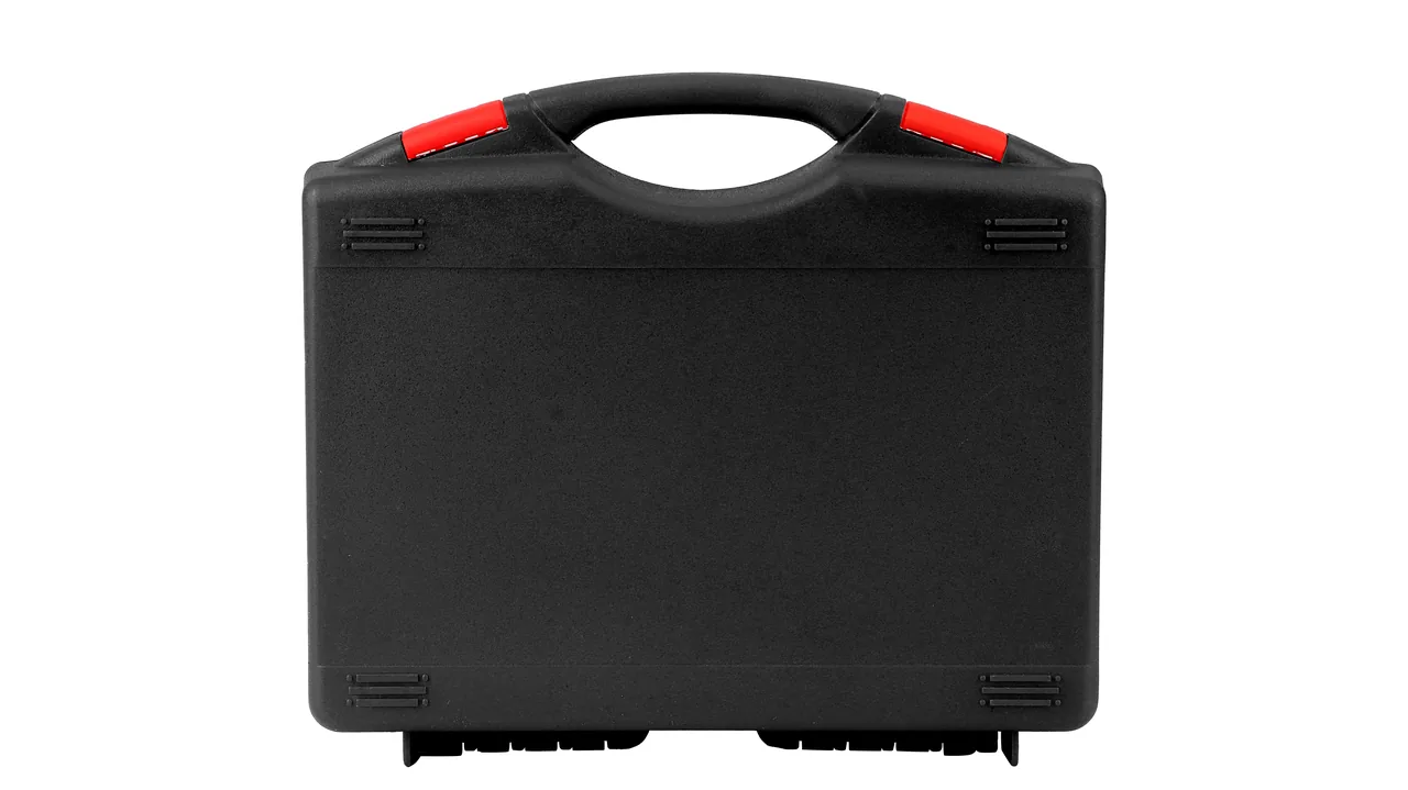
A module line rarely loses its output to the process itself. It loses it to a single shutdown while the team waits for a spare part. The laminator heating plate, the ribbon soldering head, the busbar welding unit and the conveyor rollers are expensive, slow to replace and precision-sensitive. If any of them arrives with an out-of-tolerance surface, a shifted nozzle or a bruised roller face, the whole ramp-up plan has to be rescheduled. What they share is simple: they are heavy, fragile, moisture-sensitive, oxidation-prone and vibration-sensitive, and most of them cannot be disassembled for shipping.
Protection principle: components on a PV line must be graded along three separate tracks — precision parts, electrical parts and structural parts — and then locked inside the case with four structural layers: compartmentalization, shape fixing, humidity control and vibration damping. JUNZHIJIA line-component cases are designed, tooled and delivered on exactly this logic. The sections below break the packaging requirements for laminator and ribbon soldering equipment down to an inspectable level of detail.
Table of Contents
- PV Module Line Conditions and Transport Pain Points
- Laminator Parts: Heating Plate Flatness and Vacuum Lines
- Ribbon Soldering Heads: Preserving Positioning Accuracy and Preventing Oxidation
- Busbar Welding Components: Segregating Conductive Surfaces and Solder-Sensitive Parts
- Conveyor Rollers, Belts and Traction Assemblies: Preventing Deformation
- Material and Structure Selection: From Glass-Filled PP to Aluminum Frames
- Making Sealing Levels Real: IP65/IP67 with IEC 60529 and GB/T 4208
- Cushioning Liner Systems: Combining EPE, EVA, PE and IXPE
- Compartments, Latches, Hinges and Pressure Equalization Valves
- Stacking Load and Transport Testing: ISTA, GB/T 4857 and ASTM D4169
- Temperature, Humidity, Salt Spray and Surface Protection
- Customization, OEM/ODM and Delivered Documentation
- Acceptance Criteria and Incoming Inspection Checklist
- Frequently Asked Questions FAQ
- Conclusion and Related Reading
PV Module Line Conditions and Transport Pain Points
A modern module line runs at a takt time measured in a dozen seconds per panel, so any stop is amplified into a full-line loss. Components on that line therefore behave differently from ordinary industrial spares. First, there is precision loading: laminator heating plate flatness is normally held inside a tight tolerance band, and ribbon soldering head repeatability is measured in micrometres, so plastic deformation is not recoverable. Second, there is surface sensitivity: once a busbar, ribbon or nozzle contact surface oxidizes, becomes contaminated or picks up a scratch, void rates and pull strength change immediately. Third, there is assembly shipping: heating plates often travel with vacuum lines and seals attached, and soldering heads arrive connected to servo or pneumatic units, so they cannot simply be broken down. Fourth, there is batch arrival: during a line expansion or changeover, parts arrive in large mixed quantities, so stacking and retrieval efficiency shape how fast unpacking proceeds.
Expanding the risk into failure modes makes the packaging task concrete, because each mode has its own trigger and consequence.
| Failure mode | Typical trigger | Direct consequence | Packaging countermeasure |
|---|---|---|---|
| --- | --- | --- | --- |
| Heating plate flatness drift | Resonance in long transit, stacked load | Uneven zones, bubbles or delamination | Shape-fixed support, damping pads, rigid load panel |
| Soldering head position shift | Acceleration shock, unsupported local load | Offset welds, cold joints | Precision cavity, suspended limits, cushioning liner |
| Ribbon or busbar oxidation | High humidity, condensation cycles, salt spray | Higher void rate | Desiccant, VCI film, sealed enclosure |
| Vacuum line collapse | Stacked squeeze, exposed tubing | Lower evacuation efficiency | Dedicated channels, minimum bend radius |
| Roller or belt bruising | Rough handling, internal movement | Tension fluctuation, tracking drift | Shaft-end fixing, surface film, divided cells |
| Electrical parts taking moisture | Humidity cycles during sea freight | Lower insulation, component failure | Humidity control, sealing, indicator cards |
Laminator Parts: Heating Plate Flatness and Vacuum Lines
The laminator is one of the machines a module line can least afford to stop. Its heating plate is usually a large cast-aluminum or steel structure with heating circuits and temperature sensors embedded inside and a heat-resistant coating on the face. What it fears most in transit is slow deformation caused by residual stress combined with transport vibration. Flatness is the foundation of lamination quality; once it drifts, temperature uniformity falls and the panel shows bubbles, delamination or inconsistent EVA cross-linking. The packaging therefore cannot merely wrap the plate — it has to support it.
A workable approach is to lay the working face onto a full-surface rigid pallet whose stiffness exceeds the plate's own bending stiffness, so the plate cannot sag in the middle under its own weight or a stacking load. EVA or IXPE strips around the perimeter locate and cushion the plate, but the cushioning must not press on large sensitive areas of the coating and create local pressure points. Vacuum lines, gas fittings and seals protrude, so they need dedicated channels that limit the minimum bend radius and keep them free from compression.
| Component | Precision grade | Main risk | Recommended format |
|---|---|---|---|
| --- | --- | --- | --- |
| Heating plate body | High (flatness sensitive) | Deformation, coating damage | Full rigid pallet, face-contact cushioning |
| Vacuum line assembly | Medium-high | Collapse, fitting distortion | Dedicated channels, radius limits |
| Seals and silicone parts | Medium | Aging, compression marks | Light-blocking bag, unstressed storage |
| Temperature sensors | High | Moisture, shock | Precision cavity, desiccant |
| Hydraulic/pneumatic units | Medium | Leakage, corrosion | Oil-seal protection, VCI |
Ribbon Soldering Heads: Preserving Positioning Accuracy and Preventing Oxidation

The ribbon soldering machine lays ribbon onto the busbars of the cells and welds it in place, and the head is its accuracy core. A head normally combines a welding mechanism, a hold-down mechanism, vision or sensing units and a drive section. Its mass is concentrated and its centre of gravity sits high. If it is only wrapped in foam on the outside, shock energy still travels through inertia into the guideways and bearings, and the positioning accuracy may never fully return.
For a soldering head, a three-step method works well: fix the shape, then damp, then isolate. Shape fixing means locking the head onto its dedicated base so shock is spread through the base. Damping means leaving a controlled elastic layer between base and case wall to attenuate high-frequency vibration. Isolation means placing nozzles, tips and sensors in separate sub-cavities so they cannot strike the main body.
Oxidation prevention is the second theme. Nozzles and ribbon contact areas are usually copper alloys or plated structures, and moist air with condensation cycles accelerates oxidation, which reduces solder wettability. The right configuration is a sealed main cavity with desiccant and a humidity indicator card, plus VCI film for copper parts. For coastal or high-humidity destinations, add a higher sealing grade and more humidity-control redundancy.
Busbar Welding Components: Segregating Conductive Surfaces and Solder-Sensitive Parts
Busbars and ribbons carry the current that a module collects, so their weld quality drives power output and long-term reliability. The packaging difficulty is not weight but surface condition: oxidation, oil, fingerprints or micro-scratches on a contact face all change how the weld interface behaves. Compartmentalization exists so that every conductive part travels without touching or rubbing against another.
In practice, busbars and conductive strips work well inserted into shape-fixed slots, either vertically or horizontally, with the slot slightly wider than the part thickness and enough clearance for handling. A soft pad at the slot bottom prevents end-face impact. Solder and flux consumables must be stored separately and isolated from metal parts, because volatiles can contaminate conductive faces; sealing and desiccant matter here too, since flux absorbs moisture and changes activity, which affects weld consistency.
| Component | Sensitive point | Segregation method | Auxiliary protection |
|---|---|---|---|
| --- | --- | --- | --- |
| Busbars and conductive strips | Contact faces, end faces | Shape-fixed slots, one part per position | Sulfur-free pads, anti-oxidation paper |
| Ribbon spools | Surface oxidation, deformation | Core fixing, separate cavity | Desiccant, VCI film |
| Nozzle assemblies | Locating faces, orifice | Dedicated precision cavity | Anti-shock foam, limit ring |
| Flux and solder | Moisture, volatiles | Isolated from metal parts | Sealed bottle, absorbent pack |
| Terminals | Plating, threads | Divided tray | Anti-rust paper, protective sleeve |
Conveyor Rollers, Belts and Traction Assemblies: Preventing Deformation
Conveyor rollers, belts and traction assemblies are long or flexible parts, so their packaging priorities differ from precision components: the goal is resisting bending, resisting compression and resisting abrasion. A roller is usually a metal core with a rubber or coated surface, and a permanent compression mark from a single point load will disturb line speed stability and cause belt tracking drift. Belts and timing belts develop non-recoverable internal stress if bent below their recommended radius.
The sensible approach is to support rollers at their shaft ends so they act as a simple beam, rather than leaving the middle unsupported under its own bending moment. Several rollers can be arranged in parallel on a divided pallet with separators between layers. Belts should be coiled at the recommended bend radius, avoiding sharp creases, and wrapped with a cushioning layer to prevent chafing. When a long part exceeds the case length, an extended or modular long case is better than forcing a bend.
Rollers with bearings or taper-lock bushings also need protection against axial shock that could change preload. A common method is to fit protective sleeves on the shaft ends and apply axial limits, while the whole case is designed against internal movement so that transport vibration does not let rollers slide back and forth.
Material and Structure Selection: From Glass-Filled PP to Aluminum Frames
The case material sets the ceiling for protection and the total cost of ownership. PV line component cases are commonly injection-moulded engineering plastic, rotomoulded, aluminum-framed or steel. Light weight, impact resistance, weathering and stackability constrain one another, so the choice should follow part weight and transport mode.
| Material/structure | Impact | Weight | Weathering | Tooling/unit cost | Best fit |
|---|---|---|---|---|---|
| --- | --- | --- | --- | --- | --- |
| PP injection case | Medium | Light | Medium | Medium tooling, low unit | Small parts, batch circulation |
| Glass-filled PP | Medium-high | Lighter | Medium-high | Medium-high tooling | Higher load-bearing parts |
| ABS/PC case | Medium-high | Light | Medium | High tooling | Appearance and precision parts |
| Rotomoulded PE | High | Medium | High | High tooling, medium unit | Large, heavy, outdoor |
| Aluminum frame case | High | Medium | High | Profile machining, custom | Very long or heavy, framed |
| Steel case | High | Heavy | Medium (coated) | Welded fabrication | Extreme loads, fixed stations |
Structurally, ribs, radii, flanges and double walls are the main stiffness tools. Corners and stacking faces concentrate stress, so they usually need extra thickness or corner fittings, and the lid-to-body mating face must be wide enough to guarantee seal compression. Where a case must have a window or port for an external connection or ventilation, that opening should be locally reinforced and fitted with a sealing structure so it does not become the weak point for stiffness and sealing.
Selection should also count lifecycle cost rather than unit price alone. Injection-moulded cases carry tooling cost but offer low unit cost, good consistency and recyclability; rotomoulded cases cost more to tool but suit large and heavy parts with uniform walls and strong weathering; aluminum frame cases can be machined to fit very long laminator parts, though galvanic corrosion at dissimilar-metal contacts needs insulation or isolation. Steel is the strongest but its weight and coating maintenance are a long-term burden, better suited to fixed stations than frequent circulation.
Making Sealing Levels Real: IP65/IP67 with IEC 60529 and GB/T 4208
The ingress protection column is the easiest one to get wrong in a purchase specification. In an IP code, the first digit covers solid objects and dust, the second covers water. IP65 means dust-tight and resistant to water jets; IP67 means dust-tight and capable of short-term immersion. The two are often used interchangeably, yet on a coastal plant or a sea-freight route the choice decides whether internal parts come back damp.
Judging should follow IEC 60529 or its equivalent GB/T 4208, and the procurement specification should state the test method and acceptance criteria. Note that an IP rating describes the case as delivered: once the lid is opened, an external fitting is added, or the gasket is replaced, the original rating no longer holds automatically. For sealing to remain stable over life, also consider gasket material and compression set, the clamping consistency of hinges and latches, and the breathing path of the pressure equalization valve. For parts with electrical interfaces such as Solar Inverter Cases, the sealing choice must also balance heat dissipation against re-opening for service.
| Rating | Dust | Water | Typical fit |
|---|---|---|---|
| --- | --- | --- | --- |
| IP54 | Limited dust | Splash | Short moves in a dry workshop |
| IP65 | Dust-tight | Water jets | Normal road freight, damp plants |
| IP67 | Dust-tight | Short immersion | Sea freight, coastal, rainy regions |
| IP69K | Dust-tight | High-pressure hot water | Washdown stations (special need) |
Seal performance is not decided by the gasket alone. Compression ratio, groove geometry and surface finish all matter, and a gasket that is over-compressed takes a permanent set that shortens its working life, while one that is under-compressed leaks from the first rain or washdown. In practice, the lid and body should close with a consistent gap around the whole perimeter, which is easier to achieve with reinforced rims and a regulated latch layout than with a thicker gasket. Foam-in-place and moulded silicone gaskets behave differently under cold and heat, so the operating temperature range of the destination should be part of the selection rather than an afterthought.
Cushioning Liner Systems: Combining EPE, EVA, PE and IXPE
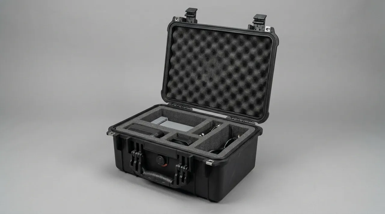
A cushioning liner is not about filling space; it absorbs shock and vibration energy in stages through a combination of material and thickness. EPE foam rebounds well and costs little, making it suitable for perimeter cushioning and void filling. EVA is denser and can be heat-formed, so it suits shape-fixed slots and precision part support. IXPE is more cross-linked with a stable closed-cell structure, good for thin durable dividers and surface layers. PE board often serves as a rigid divider and support skeleton.
Design must separate static support from dynamic damping. Static support requires the liner not to collapse under long-term stacking, so load-bearing areas need high-density material. Dynamic damping requires the liner to deform in a controlled way to absorb energy, so it needs deformation space rather than being compressed solid. Together they suggest a hard support, soft cushion and limiting face combination: a high-density EVA or PE base keeps the shape, EPE around the sides absorbs lateral shock, and IXPE or a soft facing protects critical contact faces from scratching.
The liner must also match the part's centre of gravity. When the centre of gravity is offset from the geometric centre, swaying in transit is amplified, so offset supports or counterweight cavities are needed to balance it. When several parts share one case, use one pocket per part with no contact between them, so part-to-part friction and impact do not become a new failure source. For a closer comparison of foam materials, see Internal Foam Types.
Compartments, Latches, Hinges and Pressure Equalization Valves
Compartments solve interference, latches and hinges keep the case closed and intact, and the pressure equalization valve handles the differential between inside and outside. Together they define reliability in use.
Compartment design balances protection and efficiency. Cells that are too coarse let parts move; cells that are too fine are hard to load and damage the liner. A sound approach is to group parts by size and retrieval frequency, placing high-frequency items outward, heavy items low and precision items centrally. Removable divider systems are especially useful on lines that change over often, letting the space be re-divided as the part mix changes.
Latches must not release under vibration or stacking, yet must still open and close repeatedly with ease. Hinges must carry the lid's own weight and wind load without sagging over time. The pressure equalization valve balances internal and external pressure during altitude changes, air freight or sharp temperature swings, preventing the gasket from being pulled open or the lid becoming hard to open. When selecting, check that the membrane's air permeability and water resistance match the requirement, and that the valve body can be serviced or replaced. For valve selection detail, see Pressure Equalization Valves.
| Hardware | Failure mode | Design point | Verification |
|---|---|---|---|
| --- | --- | --- | --- |
| Divider panels | Movement, liner wear | Reliable location, removable | Shake test with parts loaded |
| Latches | Vibration release, failure | Stable clamping, anti-misopen | Cycle opening, vibration test |
| Hinges | Sag, fracture | Correct load rating, smooth action | Life cycle, loaded test |
| Equalization valve | Poor breathing, water ingress | Balanced venting and sealing | Pressure differential, immersion |
Stacking Load and Transport Testing: ISTA, GB/T 4857 and ASTM D4169
Even a good structure needs test verification. Stacking load concerns whether the case and liner deform under long-term static pressure, while transport testing concerns whether protection holds through handling, drop, vibration and shock. Common frameworks include the ISTA series, the GB/T 4857 series and ASTM D4169, and the choice depends on transport mode, carrier requirements and customer agreement.
| Framework | Focus | Common use | Key points |
|---|---|---|---|
| --- | --- | --- | --- |
| ISTA series | Package and unitized transport simulation | Parcel, LTL, palletized | Drop, vibration, stacking combination |
| GB/T 4857 | Basic transport package tests | Domestic and export baseline | Stacking, vibration, shock, drop |
| ASTM D4169 | Distribution cycle simulation | North America, mixed distribution | Severity combined by cycle |
| Customer standard | Product-specific | Large accounts | Stricter thresholds and criteria |
Stacking severity should follow real warehousing: rack height, number of layers, storage duration and humidity all affect creep. For long-stored component cases, an accelerated stacking test is advisable, watching for compression set in the liner and bulging of the side walls. Drop and vibration tests should cover the least favourable attitude and the heaviest configuration, and where necessary an accelerometer can be placed inside the case so measured data shows whether the packaging needs upgrading.
Temperature, Humidity, Salt Spray and Surface Protection
Temperature and humidity are quiet killers. Day-night temperature swings during transit cause condensation inside the case, and if that water lands on conductive parts or solder, the result may only appear days or weeks after unpacking. Countermeasures include sealing, desiccant absorption, VCI corrosion protection and humidity monitoring. Desiccant quantity must be calculated from internal volume, transit duration and destination climate rather than added by habit.
Salt spray corrosion matters most for coastal freight and seaside plants, and evaluation typically follows methods such as the neutral salt spray test in GB/T 10125. For metal parts, plating, coating and passivation set the corrosion floor, but packaging can extend protection time through isolation and corrosion-inhibiting media. It should be stressed that a salt spray test is an accelerated evaluation, not a real service life, so the purchase specification should state the duration and acceptance criteria rather than treating the accelerated result as field life.
| Environmental risk | Trigger | Protection | Verification/monitoring |
|---|---|---|---|
| --- | --- | --- | --- |
| Condensation | Temperature swings, high humidity | Sealing plus desiccant | Humidity indicator card |
| Electrochemical corrosion | Salt spray, humidity | VCI plus plating | GB/T 10125 salt spray test |
| Coating damage | Friction, impact | Soft isolating layer | Visual inspection |
| Rubber aging | Light, ozone, heat | Dark, cool storage | Before/after performance comparison |
Customization, OEM/ODM and Delivered Documentation
PV line components vary widely in shape, and a standard case rarely balances precision and efficiency, so customization is the norm. The process usually starts with requirement clarification: the part list and weights, centre of gravity and outline, precision-sensitive points, transport mode and destination climate, stacking and storage conditions, and unpacking frequency and retrieval method. These are compiled into a specification that then feeds structural design and tooling.
OEM and ODM differ in design and brand ownership: OEM typically follows the customer's drawings and specification, while ODM has the supplier contributing to or leading the design. Either way, the contract should define tooling ownership, intellectual property, acceptance criteria and change control. Delivered documentation is easily overlooked but important, because a complete document set sharply reduces on-site communication effort.
| Document | Purpose | Note |
|---|---|---|
| --- | --- | --- |
| Packing list | Verify parts and quantity | One-to-one with contents |
| Drawings and specs | Structure, material, rating | Includes seal and liner data |
| Test report | Transport, sealing, salt spray results | States standard and criteria |
| Use and maintenance guide | Opening, retrieval, servicing | Covers gaskets and valves |
| Certificate and batch | Traceability | For quality tracking |
Acceptance Criteria and Incoming Inspection Checklist

Acceptance is where packaging value is finally tested. On arrival, inspect appearance and the case first, then confirm part condition, and finally check documents and quantity. Inspection needs clear criteria so that conclusions are traceable rather than resting on a vague impression that everything looks fine. Precision parts should be re-measured with agreed gauges, electrical parts should pass insulation and appearance checks before power-up, and sealing parts should be checked for compression marks, aging and deformation.
| Inspection item | Example criterion | Non-conformance action |
|---|---|---|
| --- | --- | --- |
| Case appearance | No cracks, no severe deformation | Record and assess contents |
| Gasket | No compression marks, no debonding | Replace and retest |
| Liner | No collapse, no debris | Replace liner |
| Heating plate flatness | Within agreed tolerance band | Re-measure, repair or scrap |
| Soldering head locating face | No impact marks, no rust | Clean, recheck accuracy |
| Conductive surfaces | No oxidation, oil or scratches | Clean and assess |
| Documentation | List, report and guide complete | Complete before release |
A practical inspection also needs a defined sample plan. For a batch of cases, check the first, middle and last units at minimum, and treat any gasket or liner irregularity as a batch signal rather than an isolated event. Photographs taken at unpacking are worth keeping, because they turn a later dispute about who caused the damage into a factual discussion. Where parts are heavy, use lifting equipment instead of levering them out by hand, since the unpacking stage itself is a common source of impact damage that has nothing to do with the transport route.
Frequently Asked Questions FAQ
Q: Why can't a laminator heating plate be shipped in an ordinary wooden crate with foam?
A: The plate's core specification is working-face flatness, and a wooden crate with foam only provides perimeter cushioning. It cannot restrain the plate from sagging under its own weight or a stacking load, and once the body bends in the middle or develops a local depression, temperature uniformity falls and lamination produces bubbles or delamination that cannot be corrected by adjusting the recipe. The right approach is to support the plate on a full-surface rigid pallet whose stiffness exceeds the plate's own, so the load spreads evenly across the working face. Use EVA or IXPE strips around the perimeter for location and cushioning, but never let the cushioning press on large flat areas of the coating and create concentration points that mark the surface. Vacuum lines, gas fittings and seals protrude, so they need dedicated channels with a limited bend radius and no direct compression. Finally, confirm the design with a stacking test that measures deformation under long-term pressure, rather than treating a single drop test as evidence that the package is fit for release.
Q: What usually causes ribbon soldering head positioning accuracy to drop after transport?
A: The most common cause is shock energy bypassing the external cushioning and reaching the guideways and bearings. A soldering head has concentrated mass and a high centre of gravity, so if it is simply wrapped in foam, the head shifts inside the cavity during a drop and the impact acts directly on precision mating surfaces. The second cause is that nozzles, tips and other fragile items have no separate sub-cavity, so they collide with the main body and shift out of position. The third is insufficient internal restraint, so repeated movement during hours of vibration gradually changes bearing preload. The remedy follows three steps. Lock the head to its dedicated base first, so shock disperses through the base rather than the guides. Then set a controlled elastic layer between base and case wall to attenuate high-frequency vibration. Finally isolate fragile items into sub-cavities, and verify the whole assembly with a transport test that records actual acceleration inside the case.
Q: How should IP65 and IP67 be chosen for PV line component cases?
A: The deciding factors are the transport and storage environment, not the price of the case. For short in-plant moves in a dry workshop, IP54 or IP65 is enough. For normal road freight with moderate destination humidity, IP65 with full dust protection and water-jet resistance is usually sufficient. For sea freight, coastal plants or rainy regions, choose IP67 with dust-tight construction and short-term immersion capability, so the case tolerates accidental water contact during handling and prolonged high humidity. Judging should follow IEC 60529 or the equivalent GB/T 4208, with the test method and acceptance criteria written into the purchase specification. Remember that an IP rating holds only for the case as delivered. After the lid is opened, an external fitting is added or a gasket is replaced, it no longer applies automatically. A second point is frequently missed: a sealed cavity crossing a temperature or altitude swing will breathe through the gasket unless the pressure equalization valve is sized for the real internal volume, and the condensation that follows settles on exactly the surfaces the rating was meant to shield. Also confirm gasket material, latch clamping consistency and the breathing path of the pressure equalization valve before releasing the specification.
Q: Why does ribbon and busbar packaging place such emphasis on oxidation prevention?
A: Because their weld quality is extremely sensitive to surface condition. Once a copper or plated conductive face oxidizes, becomes contaminated or picks up micro-scratches, wettability changes, and the result appears as a higher void rate and fluctuating pull strength that may only be discovered during end-of-line testing. High humidity, condensation from day-night temperature swings and salt spray are the main drivers during transit, so packaging starts with isolation and humidity control: a sealed main cavity with desiccant and a humidity indicator card, plus VCI film for copper parts. Solder and flux must be stored separately and isolated from metal parts, because volatiles can contaminate conductive faces, while flux that absorbs moisture changes activity and affects weld consistency. Ribbon, busbar and solder-sensitive components are therefore given separate compartments rather than sharing one cavity, since a single scuffed pad can scrap every joint on a panel. For coastal or high-humidity destinations, raise the sealing grade and add humidity-control redundancy, unpack promptly on arrival, and re-verify the welding parameters before the parts return to the line.
Q: Should the cushioning liner be EPE, EVA or IXPE?
A: The three are usually combined rather than chosen exclusively, and the right mix depends on the load each area carries. EPE rebounds well and costs little, so it suits perimeter cushioning and void filling. EVA is denser and can be heat-formed, making it good for shape-fixed slots and precision part supports. IXPE is more cross-linked with a stable closed-cell structure, suitable for thin durable dividers and contact faces, while PE board often serves as a rigid divider and support skeleton. Design must distinguish static support from dynamic damping. Load-bearing areas need high-density material to resist long-term stacking collapse, while shock-absorbing areas need controlled deformation space rather than being compressed solid. A typical combination uses a high-density EVA or PE base to hold the shape, EPE around the sides for lateral shock, and IXPE at critical contact faces to prevent scratching. When several parts share a case, use one pocket per part and offset the supports to match the centre of gravity.
Q: How should case stacking capacity be verified to be considered reliable?
A: It is not enough to confirm that the case does not crush. The liner and the parts must also be checked for deformation under long-term static pressure, because that is what a warehouse actually applies. Verification should follow real storage conditions, since rack height, number of layers, storage duration and humidity all affect creep in plastics and foam. An accelerated stacking test is therefore advisable, watching for compression set in the liner, bulging of the side walls and changes in the loaded faces of the parts. Drop and vibration tests should cover the least favourable attitude and the heaviest configuration, and where needed an accelerometer placed inside the case provides measured data for deciding whether the packaging needs upgrading. The case itself should carry its maximum stacking tiers, single-unit mass and centre of gravity, so a warehouse does not over-stack to save floor space; that marking is part of the verification rather than a decorative label. If ISTA, GB/T 4857 or ASTM D4169 is used, the report should state the selected procedure, the test severity and the acceptance criteria, instead of a single broad statement that the case passed.
Q: What steps are normally involved in customizing a PV line component case?
A: It usually begins with requirement clarification. Provide the part list and individual weights, centre of gravity and outline dimensions, precision-sensitive points, transport mode and destination climate, stacking and storage conditions, and unpacking frequency. These are compiled into a specification that feeds structural design covering material, wall thickness, rib layout, compartment scheme, sealing grade and cushioning liner. Tooling or profile machining follows, then a sample case trial fit and test verification, after which the product moves to volume production. The sample stage is the point of control: fit, lid closure force, liner compression and seal condition are signed off on the physical case, and any change to the part geometry after that approval reopens the design rather than being absorbed silently on the line. In an OEM or ODM arrangement, the contract should also define tooling ownership, intellectual property, acceptance criteria and change control, because these points cause most late disputes. Delivered documentation matters too. A packing list, drawings and specifications, test reports, a use and maintenance guide and a batch certificate all reduce on-site communication and troubleshooting effort, and they make it far easier to trace a problem back to a specific production batch if something goes wrong later.
Q: Which acceptance criteria are most often overlooked during incoming inspection?
A: The ones most often skipped are gasket condition, liner state and documentation completeness. Many sites inspect only the appearance of the parts and ignore whether the gasket shows compression marks, debonding or aging, even though these directly affect future protection. If the liner collapses or sheds debris, it becomes a new source of contamination and impact. Precision parts should be re-measured with agreed gauges, electrical parts should pass insulation and appearance checks before power-up, and conductive parts should be confirmed free of oxidation, oil and scratches. In addition, the inspection record should correspond one-to-one with the packing list, and every non-conformance should record its disposition to form a traceable closed loop rather than being released on a vague impression that everything looks fine.
Conclusion and Related Reading
Protecting PV line components in transit means quantifying precision, surface and electrical risks, then sealing each one off layer by layer. JUNZHIJIA, made by Kexin New Materials (Guangdong) Co., Ltd., delivers compartment customization, liner tooling, OEM/ODM and documentation as one service.
Related Reading