

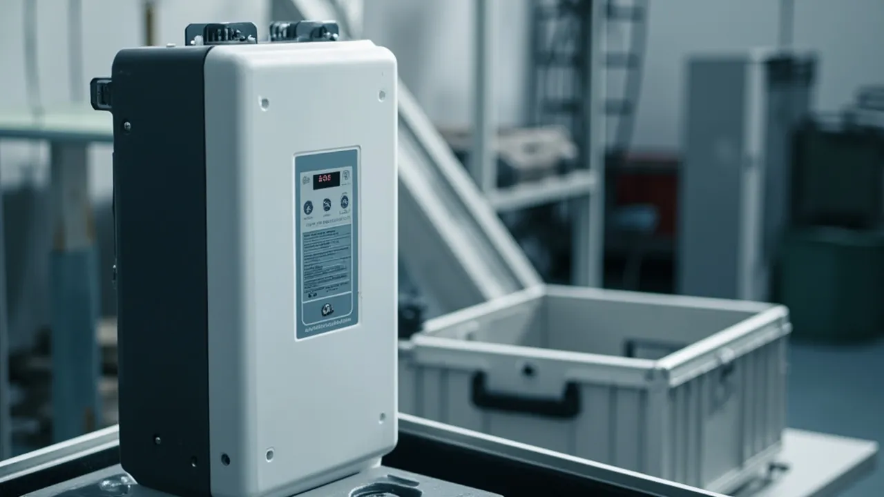
A solar inverter is a device that looks rugged and tolerates shock poorly. Its enclosure carries an outdoor protection rating, yet inside it holds large magnetic components, thin-wall heatsink fins, fan bearings, high-capacity electrolytic capacitors and precision control boards. The conclusion first: an inverter transport case must cover two things at once. Outdoor weathering, meaning the case itself must survive ultraviolet radiation, salt spray, rain and temperature cycling so that outdoor handling and temporary staging do not become a corrosion incident. And shock protection, meaning large-mass components must be reliably restrained against vibration fatigue and impact displacement. Its technical requirements should be built around the safety requirements of the IEC 62109 series for the inverter itself, the IP grades of IEC 60529 / GB/T 4208, the environmental test methods of the IEC 60068-2 and GB/T 2423 series, and the transport test methods of ISTA and GB/T 4857.
The logistics chain for a solar project is usually more exposed than for most industrial equipment: factory packing, long-haul road transport, port yard staging, sea freight, destination customs clearance, inland transport to site, secondary handling on site, temporary open-air storage, and only then installation. Across that chain the equipment spends long periods outdoors or semi-outdoors, and the packaging often has to carry responsibility it was never designed for. It becomes both a shipping case and a temporary site storage case.
At the same time, inverter value density is not low. A string inverter typically weighs between 10 and 60 kilograms, while large string and central models can reach several hundred kilograms. The heatsink is a thin-wall aluminium extrusion, the fan is a rotating assembly with a bearing, the electrolytic capacitor is a heavy component with leads and a can, and the LCD or OLED display panel is brittle. Any uncontrolled drop or sustained vibration can produce a hidden failure in which the exterior looks perfect while the interior is already damaged.
This article is written for logistics and site management engineers at solar EPC firms, and for packaging engineers and buyers at inverter manufacturers. It covers environmental factor analysis, material selection, structural design, standards citation and validation methods.
Contents
- 1. Inverter Transport Risk Profile: Heavy, Large, Thin-Wall Heatsinks
- 2. Five Failure Categories for Inverters in Transit
- 3. Four Outdoor Weathering Factors: UV, Salt Spray, Rain, Temperature Cycling
- 4. IEC 62109 and IEC 60529: Device Ratings Versus Case Ratings
- 5. What IP65 and IP66 Actually Mean, and Common Misreadings
- 6. Case Materials and UV Resistance: Why Ordinary Plastics Fail
- 7. Salt Spray Protection and Metal Hardware Corrosion Control
- 8. Shock Design: Cushioning Heavy Masses and Avoiding Rigid Clamping
- 9. Local Protection for Heatsinks, Fans and Display Panels
- 10. Protecting Connectors, Cables and Mounting Brackets
- 11. Condensation Control and Pressure Equalization
- 12. Stacking, Handling and Forklift Operations
- 13. Transport Validation: ISTA, GB/T 4857 and Drop Testing
- 14. Common Misconceptions and Selection Recommendations
- Frequently Asked Questions
- Conclusion and Related Reading
1. Inverter Transport Risk Profile: Heavy, Large, Thin-Wall Heatsinks
Risk factor one: high mass with an offset centre of gravity. The heaviest internal components are the magnetic parts, such as inductors and transformers, and the heatsink. They usually cluster on one side or at the bottom, creating an offset centre of gravity. The consequence is that acceleration and deceleration during transport generate an overturning moment inside the case rather than a simple horizontal push.
Risk factor two: large outline with low panel stiffness. String inverter enclosures are mostly thin-gauge sheet metal or die-cast aluminium. Large flat areas dent easily under lateral pressure, and the exterior coating is easily damaged by friction and impact. A damaged coating point becomes the starting point for later corrosion.
Risk factor three: thin-wall heatsink fins. The fins of an aluminium extrusion are usually very thin and bend or flatten under lateral load. Flattened fins reduce heat dissipation efficiency and are very difficult to restore in the field.
Risk factor four: rotating components and brittle components coexist. The fan is a rotating assembly whose bearing suffers from sustained vibration, while the display panel is brittle and cracks under point loading.
Risk factor five: long environmental exposure. Solar sites rarely have covered warehouses, and equipment may sit outdoors for weeks before installation. This means the case material must tolerate UV aging and rain, or the case will fail first.
| Risk factor | Concrete manifestation | Main load type | Design response |
|---|---|---|---|
| --- | --- | --- | --- |
| High mass, offset centre of gravity | Overturning tendency, high local pressure on the base | Inertial moment, static load | Centre-of-gravity alignment, reinforced base, anti-tip retention |
| Large low-stiffness panels | Enclosure denting, coating damage | Lateral pressure, friction | Surface contact support, soft padding, no point contact |
| Thin-wall heatsink fins | Fin bending and flattening | Lateral impact, compression | Local clearance pockets, dedicated support blocks |
| Rotating and brittle components | Bearing damage, panel cracking | Sustained vibration, point load | Overall cushioning, displacement limits, no rigid contact |
| Long outdoor exposure | Case aging, metal corrosion | UV, salt spray, rain | Weather-resistant materials, sealing, corrosion protection |
2. Five Failure Categories for Inverters in Transit
Category one: enclosure and coating damage. Manifesting as dents, scratches and paint loss. Such damage looks minor, but it destroys the corrosion protection basis of the enclosure. In coastal or industrially polluted environments, an unrepaired coating break expands progressively into a rusted area.
Category two: cooling system damage. Bent fins, fan noise or seizure, deformed fan brackets. Reduced cooling capacity directly affects the derating behaviour and service life of the inverter.
Category three: electrical connection damage. Loosened internal harness terminals, capacitor leads under stress, deformed DC-side and AC-side terminals. These failures often cannot be detected in factory testing but surface together during on-site grid connection.
Category four: display and control panel damage. Cracked LCD or OLED, deformed key structures, broken transparent windows.
Category five: latent performance drift. Sustained vibration can loosen magnetic cores, change inductance and reduce bolt preload. This category is the hardest to trace because the exterior is completely normal.
| Failure type | Specific location | Trigger | Inspection method |
|---|---|---|---|
| --- | --- | --- | --- |
| Enclosure and coating | Housing, mounting ears, door panels | Impact, friction, compression | Visual inspection plus coating thickness measurement where needed |
| Cooling system | Heatsink, fan, air duct | Lateral impact, sustained vibration | Visual fin deformation check plus manual fan rotation check |
| Electrical connections | Terminals, harnesses, capacitor leads | Vibration fatigue, displacement pull | Terminal torque recheck plus visual inspection |
| Display panel | LCD or OLED, keys, window | Point load, vibration | Powered illumination check |
| Latent drift | Magnetic cores, inductors, fasteners | Long-term vibration | Powered functional test plus torque recheck at critical points |
3. Four Outdoor Weathering Factors: UV, Salt Spray, Rain, Temperature Cycling
Factor one: ultraviolet radiation. The UV band in sunlight breaks polymer molecular chains, showing up as discolouration, chalking, embrittlement and loss of strength. UV aging is slow but irreversible, and it accelerates markedly when the case material has no stabiliser package.
Factor two: salt spray. Coastal projects and sea freight involve a chloride environment. Chloride ions break down the passive film on metal surfaces and accelerate corrosion. The mechanisms differ between galvanised parts, carbon steel and aluminium, but the common point is that corrosion rate is closely tied to chloride concentration, humidity and temperature.
Factor three: rain and standing water. Prolonged rain tests the sealing structure and drainage design of the case. If the case sits in standing water in an open yard, water remains on surfaces for long periods, accelerating corrosion and material aging.
Factor four: temperature cycling. Day-night temperature swings make the case and its internal air expand and contract repeatedly, producing a breathing effect: internal air exchanges with the outside through seals and small gaps and brings external moisture in. Temperature cycling is the main cause of condensation and an accelerator of seal fatigue.
| Environmental factor | Main target | Failure manifestation | Design response |
|---|---|---|---|
| --- | --- | --- | --- |
| UV radiation | Plastic case body, rubber seals, labels | Discolouration, chalking, embrittlement, strength loss | UV-stabilised materials, weather-resistant labels, shade design |
| Salt spray | Metal latches, hinges, frames, fasteners | Rust, coating spalling, sticking mechanisms | Stainless steel or corrosion treatment, avoid dissimilar metal contact |
| Rain and standing water | Case surfaces, gaskets, drainage paths | Water ingress, pooling, mould | IP grade, sealing structure, ground clearance |
| Temperature cycling | Internal air, seals, inserts | Condensation, seal fatigue, insert deformation | Breather valve, desiccant, wide-temperature materials |
4. IEC 62109 and IEC 60529: Device Ratings Versus Case Ratings
The scope of the IEC 62109 series. IEC 62109-1 and IEC 62109-2 are safety requirements for power conversion equipment in photovoltaic power systems, covering structural, electrical, thermal, mechanical and marking safety elements. They govern the safety design of the inverter itself, not the transport packaging. However, their requirements on enclosure protection, mechanical strength, temperature rise and marking directly identify which parts the packaging must protect.
The scope of IEC 60529 / GB/T 4208. These are enclosure protection (IP code) standards governing the ability of an enclosure to resist external solids and liquids. The key distinction is that IEC 60529 describes the protection capability of the inverter enclosure itself, not the protection capability of the transport case.
What that distinction means in engineering terms.
- An inverter enclosure rated IP65 or IP66 can resist water jets after installation. That does not mean it tolerates prolonged immersion, and it does not mean it resists standing water during transport.
- The IP grade of the transport case is an independent specification that should be set from the distribution environment, rather than assuming that IP65 on the inverter means IP65 on the case is sufficient.
- The goal of the case is not to match the inverter rating but to cover the harshest environment the inverter may encounter anywhere along the logistics chain.
| Standard | Governs | Main content | Role in packaging design |
|---|---|---|---|
| --- | --- | --- | --- |
| IEC 62109-1 and -2 | Power conversion equipment itself | Structural, electrical, thermal, mechanical, marking safety | Identifies sensitive areas and structural features to protect |
| IEC 60529 / GB/T 4208 | Enclosure protection ratings | Definition and verification of solid and water protection | Defines the IP grade requirement for the case |
| IEC 62262 | Mechanical impact protection for enclosures (IK code) | Impact energy levels | Reference for impact resistance requirements |
| IEC 60068-2 and GB/T 2423 series | Environmental test methods | Temperature, humidity, vibration, salt spray, shock | Provides methodology |
| IEC 60068-2-52 and similar salt mist methods | Salt spray corrosion testing | Salt mist cycling conditions | Evaluates metal and coating corrosion resistance |
| ISTA series | Transport package performance testing | Drop, vibration, stacking and more | Packaging performance validation |
| GB/T 4857 series | Basic tests for transport packages | Drop, vibration, stacking, compression | Domestic transport validation basis |
| ASTM D4169 | Shipping container performance testing | Distribution cycle simulation | Common for export scenarios |
| MIL-STD-810H | Environmental test methods | Temperature, humidity, vibration, shock, salt spray methods | Methodology reference only, not a military certification |
| UL94 | Flammability of plastics | Case and insert flammability rating | Material flammability assessment |
Framing MIL-STD-810H correctly. It is an environmental test methods standard. In a commercial packaging context, citing it means that the corresponding methods were used to run environmental tests, not that a military certification was obtained. See MIL-STD-810H environmental testing and case compliance.
5. What IP65 and IP66 Actually Mean, and Common Misreadings
IEC 60529 uses two digits: the first covers solid ingress including dust, the second covers water.
| IP rating | Dust | Water | Positioning in solar inverter logistics |
|---|---|---|---|
| --- | --- | --- | --- |
| IP54 | Limited dust protection | Splash resistant | Covered warehouse, short transfer |
| IP65 | Dust tight | Jet-water resistant | General outdoor transport and staging |
| IP66 | Dust tight | Powerful jet-water resistant | Open yards, heavy rainfall regions |
| IP67 | Dust tight | Short-term immersion | Sea freight, yards prone to standing water |
| IP68 | Dust tight | Continuous immersion | Special cases, usually unnecessary |
Misreading one: IP66 means absolutely watertight. It actually means no ingress under defined test conditions for a defined duration. Aged seals, more open-close cycles and sand or dust on sealing faces all weaken real performance.
Misreading two: the inverter is IP66 so the case can be anything. The inverter rating addresses rain and spray in its installed state, while the case faces repeated handling, yard flooding, sea freight salt spray and internal condensation. The loads and environment are entirely different.
Misreading three: looking only at the case rating and ignoring seals and hardware. Protection is limited by the weakest link. Gaskets, hinges, latches, breather valves and label holes are all potential leak paths. For further reading, see waterproof case IP ratings explained and IP67 protective case design and validation.
Misreading four: ignoring the IK impact rating. The IK code defined in IEC 62262 describes an enclosure's resistance to mechanical impact. For cases in open yards, impact resistance matters as much as water resistance, because a single cracked shell defeats the entire sealing design.
6. Case Materials and UV Resistance: Why Ordinary Plastics Fail
Three levels of material system.
Level one: general-purpose plastic cases in PP or HDPE. Low cost, recyclable, suitable for light and medium inverters. The key precondition is a UV-stabilised formulation, otherwise the case chalks rapidly in open air. Suited to covered storage and short-distance transport.
Level two: rotomolded cases. One-piece moulding with greater wall thickness and strong impact resistance, plus considerable freedom in sealing structure design. Rotomolded cases are the most commonly selected option for outdoor weathering scenarios, and wall thickness plus reinforcing ribs can raise compression capability.
Level three: metal frame with composite body. A steel or aluminium frame provides structural strength while outer panels provide protection. Strength is high and heavy loads can be carried, but corrosion protection and dissimilar metal contact corrosion need careful treatment.
Practical approaches to UV resistance.
- Choose a formulation with UV stabilisers such as hindered amine light stabilisers and UV absorbers, and require the supplier to provide the material grade and weathering data.
- Avoid materials with a high recycled content, because impurities in recycled material accelerate aging.
- Labels and tapes must also be weather resistant, otherwise they peel within months and the marking becomes ineffective.
- Darker materials absorb more heat and raise internal temperature, so in hot regions the trade-off between colour and temperature rise must be considered.
For cross-comparisons of material systems, see case foam material comparison and plastic protective case selection basics.
7. Salt Spray Protection and Metal Hardware Corrosion Control
The salt spray threat to case hardware. Latches, hinges, handle shafts, wheel axles and fasteners are the most corrosion-prone parts of a case. The consequences go beyond appearance and include sticking mechanisms, reduced clamping force and lower structural strength.
Four principles of corrosion protection.
Principle one: material first. Prefer stainless steel, such as the 304 or 316 family, or metal parts with reliable surface treatment. In coastal and sea freight scenarios, 316 stainless steel clearly outperforms 304 against chloride corrosion.
Principle two: avoid dissimilar metal contact. Metals of different potential in contact in a wet environment form a galvanic couple that accelerates corrosion of the more active metal. Design should isolate dissimilar metals with insulating washers or coatings.
Principle three: avoid water-trapping geometry. Grooves, blind holes and horizontal ledges collect water and salt. The structure should drain freely.
Principle four: serviceability. Metal parts should be replaceable rather than moulded permanently into the case.
On citing salt spray testing. IEC 60068-2-52 and the corresponding methods in the GB/T 2423 series provide salt mist cycling test methods. When quoting results, state the test conditions including salt concentration, temperature and cycle count, otherwise the data lacks comparability.
8. Shock Design: Cushioning Heavy Masses and Avoiding Rigid Clamping
Core principle: cushion rather than clamp. Inverters are heavy, and rigid clamping creates sustained high stress at the clamping points under vibration, which over time can deform the enclosure or damage the coating. The sensible approach is to let the insert carry load, let the structure limit travel and let displacement remain controlled.
A three-layer shock structure.
Layer one: base cushioning. A cushioning layer between the case floor and the equipment absorbs vertical impact. Thickness and material should be selected from equipment weight and expected drop height.
Layer two: horizontal retention. Molded inserts or locating blocks limit horizontal displacement, allowing slight elastic movement without free rattle. The key parameter is the maximum permitted displacement, typically defined in millimetres on the drawing.
Layer three: top restraint. Light preload at the top prevents vertical bounce. Excessive preload instead transmits impact directly into the top of the equipment.
Centre of gravity alignment and anti-tip design. Because the inverter centre of gravity is offset, the internal layout should place the overall centre as close to the geometric centre of the case as possible, with extra support on the offset side. The centre of gravity position and lifting points should be marked on the case.
For cushioning design methods, see cushion liner design and shock absorption and sealing and shock-resistant structure design.
9. Local Protection for Heatsinks, Fans and Display Panels
Heatsink protection. Fin orientation determines the sensitive direction: most aluminium extrusion fins bend under lateral load. The insert should provide a clearance pocket in the heatsink area so the fins touch no rigid surface. Where contact is unavoidable, use a low-hardness, low-resilience soft material and maximise the contact area.
Fan protection. Fan blades are usually plastic and the bearing is sensitive to axial and radial impact. The key points are to prevent the fan from taking impact directly and to avoid sustained high-frequency vibration. For models with the fan on the side of the case, add extra cushioning on that side.
Display panel protection. LCD and OLED panels are brittle, and breakage is usually caused by point loading combined with local bending. The key points are: no rigid protrusion pressing on the panel area, avoiding panel orientation toward the loaded side of the case, and adding a protective pad over the panel where necessary.
How to implement local protection.
- Clearance pocket: leave a gap at sensitive areas so external force is not transmitted there.
- Dedicated support block: design a support block specifically for the heatsink to spread the load.
- Contour conformity: use soft inserts that follow the contour of fan and panel areas.
10. Protecting Connectors, Cables and Mounting Brackets
Connector protection. DC-side and AC-side connectors, such as the widely used MC4-type DC connectors, are easily compressed or knocked during transport. Key points are protective caps, avoiding tensile load on connectors through cables, and keeping rain and sand out of contacts.
Cable protection. Cables supplied with the unit should be packed separately and fixed inside the case so they cannot swing freely. A swinging cable creates repeated bending at its ends, and under sustained vibration the internal copper strands can fracture.
Mounting bracket protection. Wall brackets and floor brackets are usually sheet metal parts with limited bending resistance. They should be laid flat with surface contact support and must not be stacked under pressure, and sharp bracket edges must not scratch other components.
Insert zoning recommendation. Divide the main inverter body, brackets, cables and accessories into separate cavities and mark the correspondence on the insert so everything can be verified as soon as the case is opened. For design methods, see custom foam insert design guide.
11. Condensation Control and Pressure Equalization
The condensation chain. Temperature cycling causes internal air to expand and contract, air exchanges with the outside through sealing gaps, moisture enters the case, temperature falls below the dew point, and condensation forms. For equipment containing electronics, condensation is the highest-risk hidden environmental factor, because it often disappears by the time the case is opened while leaving corrosion traces inside the equipment.
Three control measures.
Measure one: sealing plus a breather valve. A hydrophobic breather valve equalises pressure, reducing the moisture exchange caused by breathing while maintaining the IP rating. For the principle, see case pressure equalization valve.
Measure two: desiccant and humidity indication. Size the desiccant from internal free volume, target humidity and expected duration, and fit a humidity indicator card so moisture can be judged on opening.
Measure three: avoid residual water and contaminants inside the case. Confirm the equipment is dry and free of condensation before packing, avoid residues from water-containing cleaners, and avoid packaging materials that release moisture vapour.
On seal material selection. Gaskets take compression set under temperature cycling and gradually lose sealing force. Gasket material, hardness, compression amount and replacement interval should all be specified in the technical agreement. See case seal materials and structure.
12. Stacking, Handling and Forklift Operations
Stacking constraints. Inverters are heavy, and stacking load travels through the case and insert directly into the equipment. Most manufacturers specify a limit on permitted stacking for the inverter, and the packaging design must not exceed it.
Matching the handling method.
- Manual handling: suitable for models under 30 kg, with ergonomically designed handles.
- Two-person handling: 30 to 60 kg models, with symmetrical handles on both sides.
- Forklift handling: provide forklift pockets in the base or compatibility with standard pallets, so forks do not press directly on the equipment.
- Crane lifting: large models should have marked lifting points and use dedicated rigging.
Trade-offs with wheels and trolley handles. For models that must be moved frequently, heavy-duty wheels and a trolley handle greatly reduce manual effort, but wheels add weight and cost and can become a weak point under stacking load. For related design, see case wheels and trolley handle design.
Handling markings. The case should show the centre of gravity, lifting points, permitted stacking layers and orientation marks. Markings should use weather-resistant materials so they do not peel in open air.
For overall handling structure design, see portable transport box design and case lock customization options.
13. Transport Validation: ISTA, GB/T 4857 and Drop Testing
A three-layer validation structure.
Layer one: material and component weathering validation. UV resistance of the case material, salt spray performance of metal parts and temperature cycling of seals can be validated at material level using the relevant methods.
Layer two: package performance testing. Drop, vibration, stacking and concentrated impact testing on the complete case. Common procedures include the ISTA series, the GB/T 4857 series and ASTM D4169.
Layer three: system-level validation. Load a real inverter into the real case, run testing against the real distribution environment, and after testing open the case to check appearance, heatsink, fan, terminal torque and function.
Example quantified criteria.
| Validation item | Example criterion | What to record |
|---|---|---|
| --- | --- | --- |
| Drop | No case rupture, no insert displacement, no visible equipment deformation | Height, orientation, cycles, floor condition |
| Vibration | No loosened fasteners, acceptable terminal torque, no fan noise | Frequency range, duration, axis |
| Stacking | No permanent deformation, no cavity collapse | Load, duration, ambient temperature and humidity |
| Concentrated impact | No penetration of the case surface, no large-area coating damage | Impact energy, impact location |
| Temperature and humidity cycling | No condensation pooling, no material embrittlement | Temperature range, cycle count, humidity |
| Salt spray | No red rust on metal parts, normal operation | Salt spray conditions, cycle count |
On the difference between single cases and full pallets. When selecting a test procedure, state whether the test unit is a single case or a full pallet. The load and constraint conditions differ significantly, and the two are not interchangeable. For methods, see transport packaging test procedures and ISTA, GB/T 4857 transport packaging testing and ASTM D4169 distribution cycle testing.
14. Common Misconceptions and Selection Recommendations
Misconception one: the inverter already carries outdoor ratings, so packaging can be simplified. The inverter IP rating addresses rain and spray after installation and does not cover drops during transport, yard flooding, sea freight salt spray or internal condensation.
Misconception two: storing equipment outdoors in ordinary plastic cases. Cases with inadequate UV resistance chalk and embrittle within months and lose protective capability.
Misconception three: replacing cushioning with rigid clamping. Rigid clamping points on heavy equipment become stress concentrations that damage the enclosure and coating under sustained vibration.
Misconception four: ignoring the sensitive direction of the heatsink. Bent fins reduce cooling capacity and are difficult to restore.
Misconception five: evaluating the case rating but not the hardware. Latches, hinges and fasteners are the first parts to fail in salt spray environments.
Misconception six: marketing MIL-STD-810H as a military certification. This creates compliance risk.
Selection recommendation checklist:
- Establish model weight, outline dimensions and centre of gravity position as structural design inputs.
- Set IP grade and UV resistance requirements from the distribution environment, including open yards, sea freight and coastal exposure.
- Prefer UV-stabilised materials and require the supplier to provide material grade and weathering data.
- Use stainless steel or reliable surface treatment for metal parts, and avoid direct dissimilar metal contact.
- Use a three-layer insert structure of base cushioning, horizontal retention and light top preload, with a defined maximum permitted displacement.
- Design local clearance or dedicated supports for heatsinks, fans and display panels.
- Fit a breather valve, desiccant and humidity indicator card to control condensation risk.
- Provide forklift pockets or standard pallet compatibility, and mark the centre of gravity and lifting points.
- Specify the transport test procedure and quantified acceptance criteria in the technical agreement.
- Establish a case maintenance and hardware replacement plan.
On supplier selection. A solar inverter transport case requires coordinated capability across structure, materials, weathering, sealing and validation. In OEM and ODM cooperation, confirm whether the supplier can support structural drawing review, sample trial fitting, and sealing and transport test coordination. In the protective case sector, JUNZHJIA provides end-to-end support from case structure design and molded insert customization through sealing and weathering validation. Its manufacturing system under Kexin New Materials (Guangdong) Co., Ltd. can develop molded inserts by inverter model, configure weather-resistant enclosure materials and stainless steel hardware options, and cooperate on trial fitting and validation records. For selection methodology, see instrument case selection guide and how to choose a case OEM factory.
Frequently Asked Questions
Q: The inverter is already IP65 or IP66, so why does the transport case need a sealing grade? A: The two protect different objects under different conditions. The inverter IP rating describes the ability of the enclosure to resist rain and spray once installed, and its verification assumes the equipment is fixed in place, not dropped, not subject to prolonged immersion and not continuously exposed to salt spray. The transport case faces a different set of conditions: repeated handling impacts and friction, immersion in standing water in a yard, sea freight salt spray, and condensation caused by temperature cycling. Packaging failure during transit can also leave the enclosure directly exposed. The case IP grade should therefore be determined independently from the logistics chain rather than defaulted from the inverter rating. For open yards and sea freight, a grade no lower than IP65 with a breather valve and desiccant is advisable.
Q: What problems appear most often when transport cases are stored in open yards? A: Three problems dominate. The first is UV aging: without UV stabilisation the case material discolours, chalks and embrittles within months, and strength and sealing degrade together. The second is standing water and corrosion: when the case top is recessed or the base has no ground clearance, rain remains on surfaces for long periods and causes metal hardware rust and gasket degradation. The third is label failure: ordinary paper or ordinary adhesive tape labels lose adhesion under UV and rain, so marking becomes ineffective and cargo may be rejected or mis-shipped. Countermeasures include using UV-stabilised materials, providing ground clearance under the case, using stainless steel or corrosion-treated hardware, using weather-resistant labels, and stacking cases in shaded or well-drained positions.
Q: Why is rigid clamping not recommended for inverter transport cases? A: Because inverters are heavy and contain thin-wall parts, and rigid clamping creates stress concentrations at the clamping points. Sustained vibration loads those concentrations repeatedly, which over time can deform the enclosure locally, damage the coating and even affect internal component preload. The sensible approach is cushioning, retention and light preload: a cushioning layer at the base absorbs vertical impact, molded inserts limit displacement around the perimeter while leaving slight elastic movement, and the top applies light preload against bounce. The key is to define the maximum permitted displacement on the drawing as an inspectable parameter rather than relying on assembly feel. Any rigid protrusion pressing on the heatsink or the display panel should also be avoided.
Q: Why does the heatsink need a dedicated clearance structure? A: Because the fins of an aluminium extrusion are very thin, and their design load direction is along the fin height rather than lateral. If the insert or case wall applies lateral pressure during transport, the fins bend or flatten, and this deformation usually cannot be restored on site. Flattened fins obstruct airflow and reduce cooling efficiency, causing the inverter to derate under high-temperature conditions and affecting power device life in the long term. The engineering approach is to design a clearance pocket in the heatsink area so the fins touch no rigid surface. Where the structure cannot fully clear the fins, use a low-hardness, low-resilience soft material and replace point contact with large-area contact wherever possible.
Q: How does condensation form inside the case, and how can it be controlled effectively? A: The chain is as follows: temperature cycling makes internal air expand and contract, air exchanges with the outside through sealing gaps, moisture enters with that air, and when the temperature falls below the dew point the moisture condenses on cold surfaces. There are three control layers. The first reduces air exchange: use a sealing structure with a hydrophobic breather valve so gas passes through a controlled path rather than through sealing gaps. The second absorbs moisture that has entered: size the desiccant from internal free volume, target humidity and expected duration, and fit a humidity indicator card for easy judgement on opening. The third reduces the initial moisture load: confirm equipment is dry before packing and avoid residues from water-containing cleaners. The highest condensation risk scenarios are sea freight and regions with large day-night temperature differences.
Q: How should metal hardware for an inverter transport case be selected? A: Prioritise the corrosion resistance of the material itself, then surface treatment, then serviceability. In coastal and sea freight scenarios, latches, hinges, handle shafts and fasteners should preferably be stainless steel. The distinction matters: 304 stainless performs well in general environments but shows a markedly higher pitting risk in chloride environments, while 316 stainless is better against chloride corrosion at higher cost. If carbon steel parts must be used, apply reliable plating or coating and inspect after transport. Pay particular attention to dissimilar metal contact: metals of different potential in a wet environment form galvanic corrosion, which should be isolated with insulating washers or coatings in the design. All metal parts should preferably be replaceable.
Q: How is the required level of transport testing determined for the case? A: Use the logic of defining the distribution environment first, then selecting the procedure. Step one, map the complete logistics chain: the outbound mode (road, rail, sea, air), the number of handling cycles, whether forklifts are used, whether open yards are involved, the destination climate, and whether shipment is by single case or full pallet. Step two, select a procedure accordingly: the GB/T 4857 series for domestic road-dominant transport, an ASTM D4169 distribution cycle for North American export, and the relevant ISTA procedure for e-commerce or parcel channels. Step three, state whether the test unit is a single case or a full pallet, because the load and constraint conditions differ and are not interchangeable. Step four, define quantified criteria before execution. Common criteria include no case rupture, no insert displacement, no loosened fasteners, acceptable terminal torque, no fan seizure and no visible deformation. A pass without quantified criteria has little engineering meaning.
Q: Can stacking layers for an inverter transport case be set arbitrarily? A: No. The upper limit is determined by three things together: the stacking load the inverter manufacturer permits the equipment to carry, the compression capability of the case and insert, and the dynamic loads that stacking may experience in transit, since vehicle vibration and vessel motion amplify static loads. In practice, first establish the maximum permitted top load on the equipment, then calculate the load path through the case and insert, and finally validate by transport testing. Most stacking failures occur not during static storage but under dynamic transport vibration, so stacking validation should be combined with vibration testing rather than limited to static compression. The permitted stacking layers should also be marked on the case, and the marking must remain legible in open air.
Q: How should the return on investment for this packaging solution be assessed? A: Use an avoided site rework and cargo loss approach. Benefit items include fewer on-site repairs or replacements for enclosure dents and coating damage, fewer replacements caused by heatsink deformation and fan damage, fewer grid-connection commissioning faults and schedule delays caused by loosened terminals and hidden electrical damage, lower secondary packaging and covering costs during open storage, and better compliance evidence for customer audits and insurance claims. Cost items include case and insert purchase, hardware maintenance and replacement, and handling labour. In solar projects, the fully loaded cost of one on-site inverter replacement, including lifting, labour and downtime, usually far exceeds the entire packaging investment, so assessment should be based on risk exposure and project schedule rather than unit purchase price alone. Reusable circulation solutions offer clearer economics when cycled across multiple projects.
Conclusion and Related Reading
A solar inverter transport case is a dual-purpose design task driven by environment and mechanics. The core contradiction it resolves is that although the equipment carries an outdoor protection rating, the environmental and mechanical loads present during transport and temporary site storage far exceed the assumptions of its installed design case. The path can be summarized in four steps: first map the full logistics chain and identify the harshest step; then set the weathering grade and sealing grade of the case material accordingly; then design the insert and cushioning structure around the centre of gravity, heatsink, fan and panel; and finally validate through package performance testing with quantified criteria.
On the supply side, a manufacturer able to support structural design, insert customization, weather-resistant material selection and transport validation coordination substantially reduces packaging iterations and on-site cargo damage risk for solar projects. In protective case customization, JUNZHJIA supports developing molded inserts by inverter model, configuring weather-resistant enclosure materials and stainless steel hardware options, cooperating on breather and sealing structure design, and supporting trial fitting and validation records. This makes it suitable for PV equipment manufacturers and EPC firms that need stable long-term supply and OEM/ODM cooperation.
Related Reading