

Among containers for complete tool sets, the socket wrench set case sits near the difficult end of the range. The reason is straightforward. A full socket set often runs to dozens of items, most of them metal cylinders of similar diameter and near-identical silhouette; each weighs little on its own but the total is substantial. Add a ratchet handle, extension bars, a universal joint and driver bits, and the case interior must deliver dense individual location while guaranteeing that nothing shifts when the case is carried, tipped or dropped. Because sockets differ so little in shape, once location fails they roll freely, strike each other, and make counting a chore.
Engineering effort therefore concentrates not on the case shell but on two subsystems: the liner positioning system and the anti-scatter structure. The shell only needs adequate stiffness, dependable closure and a sensible protection rating. What determines daily experience is whether the liner constrains every item precisely, and whether that constraint survives the three states of lid open, case tipped and case in transit. JUNZHJIA usually obtains measured dimensions and a quantity distribution for the tool list before fixing the liner format on such projects. This article covers the case, liner, dividers, hinges, latches and marking.
The Core Problem: Heavy, Numerous, Prone to Scatter
Unpacking the engineering difficulty reveals three sets of competing demands. The first pits mass against stiffness. Socket sets use dense metal, so a mid-size set is heavy once loaded, and the base and handle carry far more load than an equivalent hand tool case. Worse, the mass is not distributed evenly: sockets cluster in localised areas, creating concentrated load points that demand extra reinforcement in the base beneath them.
The second sets item count against available space. Socket diameters span a wide range with continuous increments across dozens of positions, so the liner has to provide a matching cavity diameter for every size, with gaps of only a few millimetres between them. Too small and the socket will not enter or must be forced; too large and it rattles. High-density dimensional fit is the hardest part of socket case liner work.
The third sets location against accessibility. Tighter constraint is safer in transit and more laborious in use; looser constraint is friendlier to the hand and riskier in transit. This tension amplifies once the lid opens. A socket case is normally laid flat and opened, leaving the liner face upward with tools standing vertically in their cavities, so even a slight tilt can topple or eject anything that is not held firmly. Anti-scatter design has to solve that specific state, not merely the closed state.
With those three tensions in view, most failures in socket cases trace back to one of them being underweighted. The most useful evaluation a buyer can run is to measure the tool list and then test insertion and extraction by hand, item by item, followed by an inversion hold test, rather than judging from appearance and a piece count.
Positioning Principles: Milled Cavities, Divided Trays and Mechanical Catches
Liner positioning follows three basic approaches, each matched to a different tool mix and budget. The first is a fully milled cavity liner, where a single foam sheet is machined to the outline of each tool, so every item has its own recess shaped and dimensioned from the physical part. Milled cavities give the highest positional accuracy, an unmistakable single correct location for each tool, and the best counting efficiency. The cost is that the liner is tied to one tool list; when a tool model changes, the liner must be remade, and tooling investment is higher up front.
The second is a universal divided tray, using rectangular compartments or bar slots with elastic or flap restraint. Trays are versatile, inexpensive and survive a change of tools. Their weakness is positional accuracy: a mismatched tool rocks inside its compartment, items migrate during transport, and there is no visual signal of a missing piece. Trays suit a tool list that changes often, or applications where precise location is not critical.
The third is mechanical catching, exploiting features of the tool itself to create a hard arrest, for example seating a socket on a matched holder or hooking a ratchet handle at its tail. Mechanical catches hold most securely and do not depend on friction generated by compressing liner material, so they last longer and degrade more slowly. Their weakness is universality: they cannot accept tools the design never anticipated.
Real products combine all three. Sockets and frequently used long bars go into milled cavities; occasional or awkward accessories go into divided compartments; and the heaviest items, such as large sockets and the ratchet handle, receive an additional mechanical catch. The key to a combination is hierarchy: high-frequency items deserve precise milling, low-frequency items tolerate looser constraint, and heavy items must be mechanically secured. Mixing the three without prioritisation produces the worst outcome, with the items that need firmness held loosely and the items that need freedom held tightly. General principles of interior zoning are set out in laying out a toolbox interior.
Liner Materials: EVA, PE and Composite Foam
Liner material determines positional accuracy, feel and service life, and the practical choice sits among EVA, PE and composite foam. EVA is the most widely used: it recovers well, has a relatively fine texture, machines to clean cavity edges, and accepts higher-density formulations that generate reliable clamping on cavity walls. Its drawback is cost rising quickly with density, and the tendency of some low-density formulations to take a permanent set after sustained compression, which weakens grip over time.
PE foam is stiffer, more chemically resistant and cheaper, which suits cavities carrying heavier items or needing greater lateral rigidity. It feels firmer than EVA, machines to a less refined cavity edge, and offers less accommodation for small or complex shapes. Where both load bearing and oil resistance matter, laminating PE with EVA is common: PE for the load-bearing layer and EVA for the tool-contact cavity layer, combining stiffness with conformity.
Composite foam is a broad term covering stacked layers of different density or material. The engineering purpose is to split two conflicting needs, rigidity and conformity, across separate layers so both are satisfied at once. The critical process requirement is bond integrity between layers, because a laminate that separates under repeated insertion and vibration creates both a debris trap and a misalignment risk. Material selection should follow a sequence: establish the load-bearing requirement of the heaviest item, then the clamping precision required by the smallest, and only then choose the material and density combination.
Whatever the choice, confirm the temperature window and oil resistance. In a vehicle or a hot workshop, foam that softens at temperature lets cavities collapse, while foam that embrittles in cold may shatter in a single impact. Comparing how candidate materials behave across high and low temperature extremes during the selection stage is far cheaper than discovering the limit in service.
Milled Cavity Design: Depth, Compression Ratio and Retrieval Feel
Milled cavity design is the technical heart of a socket case liner, and three parameters govern the feel. The first is depth. Cavity depth should cover a sensible proportion of tool height: too shallow and a tipped case will release the tool, too deep and the tool sinks out of finger reach. For cylindrical items such as sockets, the usual pattern leaves a length protruding above the cavity edge so a finger can pinch and draw it out; for flat items, cavity depth slightly greater than thickness lets the fingertip lever the item up from an edge.
The second is compression ratio, meaning how much smaller the cavity is than the measured tool dimension. The cavity is made slightly undersized so material recovery generates clamping force, and that undersize figure must be controlled carefully. Too little and grip is insufficient, allowing movement in transit; too much and insertion and extraction become laborious while material fatigue accelerates. The ratio should differentiate by tool mass and surface finish, with larger values for heavy or smooth items and smaller values for light or delicate ones. Practice normally begins with a gauge-machined sample to validate feel before batch milling begins.
The third is retrieval geometry. A cavity must not only match the tool outline but also leave room for fingers. A common approach locally relieves the cavity edge to create a finger pocket between tool and wall; another leaves a through-hole or an ejection feature at the cavity floor so the tool can be pushed out from below. Retrieval geometry is most often neglected at prototype stage, because samples tend to validate that a tool goes in without validating that fingers can take it out. Acceptance should therefore include twenty consecutive retrieval cycles in a normal grip posture, noting whether any auxiliary tool or change of grip was needed.
Milled cavity design should also consider quantity headroom. Sets are arranged by size, but in practice one or two sizes are often missing or replaced; without a reserved position for a plausible addition, a later purchase means a whole new liner. Reserving spare positions is a common engineering habit, though it costs some volumetric efficiency, and the decision belongs at design stage with the user present.
Positioning the Ratchet and Long Extensions
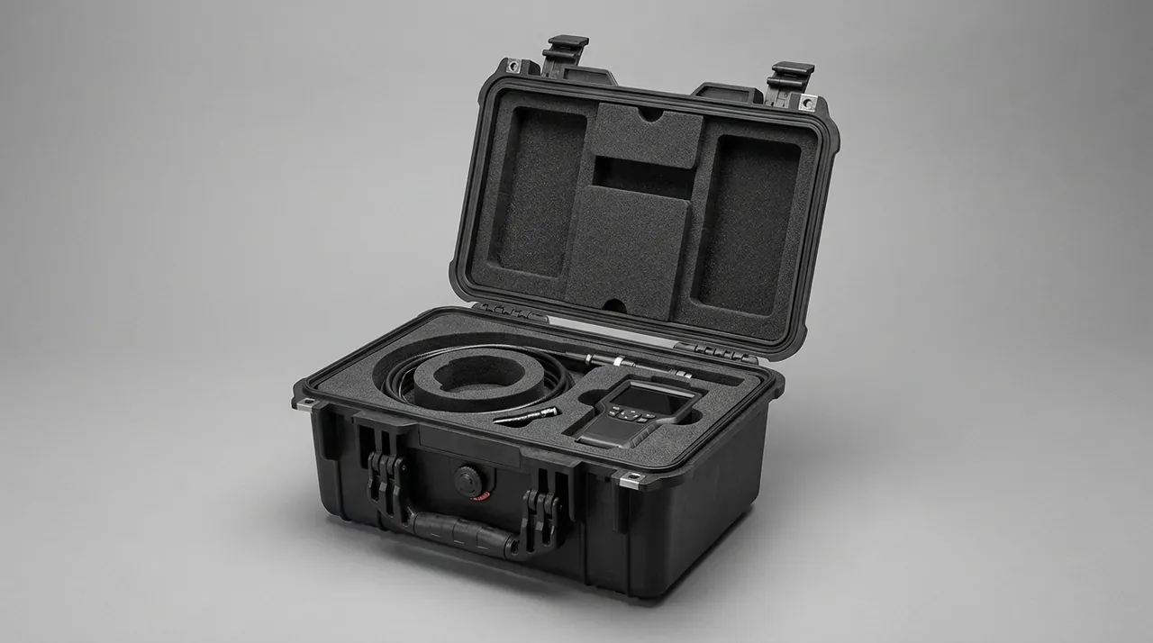
Within a complete socket set, the hardest items to position are not the sockets but the ratchet handle and the extension bars. A ratchet typically carries a pivoting head and a long handle, giving a cantilevered shape that is bulky at one end and slim at the other. Locating it requires restraining head and handle simultaneously, or in transit it will rotate about its location point and strike its neighbours with the handle end. The usual answer machines a deeper recess at the head and a narrower long groove along the handle, adding one elastic pressure point on the shaft to create two-point restraint.
Extensions, universal joints and driver bits are slender bars with small diameter and long length, and their difficulty lies in bending resistance and axial creep. A slim bar is easily excited by lateral vibration and migrates slowly along its axis. Remedies include making the cavity slightly longer than the bar with light clamping at both ends, adding a mid-span clamp to avoid turning the bar into a simply supported beam, and providing dedicated seats for the larger-diameter end fittings so their geometry creates an axial arrest.
Driver bits and adaptors are the pieces most easily lost and most likely to have no home in the liner. Two approaches exist. One groups all small items into a single lidded compartment so they can be counted as a group, which is cheap and easy to check but requires opening the small lid for access. The other mills an individual cavity for each item with elastic retention, which improves location at the cost of liner complexity. Most engineering solutions adopt the grouped compartment and add a transparent or translucent cover so a missing item is visible without opening anything.
Long bars carry one further trap: they often exceed the usable depth of the case interior, so they must lie diagonally or be stored in sections. Diagonal placement consumes more plan area and looks less tidy but avoids forcing a bend; sectional storage requires dismantling the bar and adds assembly steps. The priority should be avoiding permanent bending stress rather than achieving neatness. The fuller workflow for liner machining and density selection appears in customising an EVA foam insert.
Anti-Scatter One: Lid Compression Structure
The first and most effective line of anti-scatter defence is the compression structure inside the lid. The principle is direct: when the lid closes, a compression element on its inner face mates with the liner top surface and presses the tools down, preventing any upward movement under transport vibration. Three implementations exist: full-face, local and elastic compression.
Full-face compression applies a layer of compliant material to the lid interior so it contacts the whole liner surface when closed. It is simple and covers everything, but the compression force depends on closing travel and material deflection, so poor control of either produces a lid that does not press hard enough or one that is hard to close. It also requires good parallelism between liner top and lid interior, without which pressure becomes uneven, excessive in places and absent in others.
Local compression adds individual pads or bosses on the lid interior at the positions most likely to lift. It is efficient and tolerant of limited closing travel, and it suits protecting a small number of critical items, but it demands accurate alignment, since a misplaced pad presses onto a sharp edge or a weak feature and damages it. Elastic compression mounts compliant elements on the lid interior, such as foam blocks, elastic webbing or elastic brackets, which contact the liner and are then compressed on closing to generate preload. Elastic compression tolerates dimensional variation best and is the most common solution, though elastic parts age and belong in the maintenance plan.
Verifying compression is straightforward: load the case fully, close the lid, invert the case and tap the base, then open and inspect for tools that have left their cavities. A stricter test is a loaded inverted drop, but that damages tools and is normally reserved for type testing. In routine acceptance, the inverted tap test exposes most insufficiency.
Anti-Scatter Two: Hinge Stops and Opening Attitude
A socket case is typically used lying flat with the lid open, liner facing upward and tools standing vertically in their cavities, held only by cavity grip. If the lid opens too far, or the case is moved with the lid open, tools topple readily. Hinge stops and opening attitude therefore belong to anti-scatter design rather than to convenience alone.
The core of a hinge stop is a limit on maximum opening angle. Most socket cases open to roughly one hundred degrees, so the lid settles slightly back from vertical: it neither falls closed on its own nor tips the case centre of gravity too far. Implementation ranges from a mechanical limit built into the hinge, to a limiting strut, to a limiting webbing strap. The limit component must be rated for the lid mass, or wind and impact will deform it out of function.
Opening attitude also involves stability with the lid open. A loaded socket case concentrates mass on one side, and if the base area is small the whole case shifts its centre of gravity rearward when opened, risking a tip-over. Countermeasures include enlarging the base area, adding mass at the rear underside, and arranging the heaviest tools toward the front or middle rather than the rear. Tool arrangement is easily overlooked yet in a loaded case it is often easier to adjust than the structure itself.
A third route restrains tools through the liner surface rather than the lid. Cavity mouths can be tapered slightly inward, or the liner face can carry a thin elastic membrane so extracting a tool means first overcoming a light elastic resistance. This produces whole-liner preload, so tools do not readily jump out even with the lid open, at the cost of a slightly changed retrieval feel that users should confirm they accept at sample stage. Case lid and cover replacement logic follows a related but distinct set of rules worth consulting alongside closure-component guidance.
Anti-Scatter Three: Section Lids and Individual Catches
Where item count, mass and the requirement to stay located with the lid open all rise together, cavity grip alone is often insufficient and section lids or individual catches become necessary. Section lids divide the liner into zones, each covered by a separately hinged panel with its own compression material on the underside. The user opens only the zone needed for the current task, leaving the remaining zones under compression. The benefit is a large reduction in the exposed risk area; the cost is structural complexity, since every section lid is a moving part and a wear point.
Individual catches target specific high-value items with direct mechanical restraint. Common forms include elastic clips, rotating stop tabs, snap-fastened pressure bars and magnetic elements. Elastic clips suit cylindrical sockets and bars, with grip set by clip stiffness. Rotating tabs suit flat items: a small tab swings to press the tool down, which is highly reliable but requires an extra motion. Snap pressure bars carry several fasteners along a webbing or moulded strip, holding multiple tools at once with high efficiency but demanding accurate alignment. Magnets suit sockets particularly well because the socket is ferromagnetic, so magnetic retention adds constraint without adding an action step; the limits are modest holding force and attraction of ferrous debris, which requires periodic cleaning.
Section lids and individual catches increase liner thickness, consume case volume and add closing steps. Selection should weigh protective benefit against operating cost rather than stacking features. For routine maintenance with gentle handling, cavity grip plus elastic lid compression is normally sufficient. Section lids and catches earn their place only where the case faces long-distance transport, repeated loading and unloading, or stacking in a vehicle cargo bay. Section lid design also interacts with case stiffness: each panel needs dependable hinges and stops, which requires the shell to be rigid enough at the mounting points, or a deforming lid will prevent the panels from operating. Test methods relating to shell stiffness and load capacity are discussed in how toolbox durability and load testing works.
Missing-Item Recognition: Making a Gap Obvious
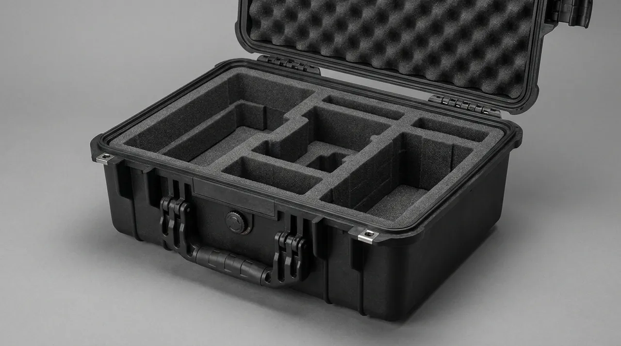
In set-based tool management, the most time-consuming step is often end-of-shift counting rather than the work itself. Checking dozens of sockets one by one takes real time, and an incomplete check means a missing item may only surface during the next job. Making a gap immediately visible is therefore a functional requirement of the liner, not a cosmetic preference.
The first route is one-to-one correspondence between cavity and tool with high-contrast marking. Printing the size beside each cavity and matching cavity shape strictly to the tool means any absence creates an obvious gap in an otherwise orderly array. This is highly efficient, but it presupposes that the liner matches the tool list precisely, which a universal tray cannot deliver.
The second route is colour layering. Using a base colour inside the cavities that contrasts strongly with the tools gives each occupied cavity a two-tone appearance, while an empty cavity shows only the base colour, so a scan from above reveals gaps quickly. The base colour also sharpens cavity edges, which helps alignment during insertion.
The third route turns counting into a structured procedure. Number the cavities in size order and print that order along the liner edge so counting becomes a sequential scan rather than a random check. Where control requirements are strict, a checklist card matching the cavity layout can be fixed to the liner or lid interior and ticked item by item. The card material must resist oil and be replaceable, since tool lists change with work content.
Missing-item recognition degrades as the liner wears. Once cavities enlarge, tools sit off position, visual orderliness declines, and a gap no longer stands out. The liner replacement interval should therefore be tied to the retention of missing-item recognition rather than to visible damage alone. When tools begin to rock noticeably in their cavities, it is time to plan replacement. Further liner selection principles appear in toolbox internal foam selection.
Case Load Capacity: Mass of a Socket Set and Reinforcement
Socket set mass concentrates in the base, so shell design must address localised concentrated load rather than uniform load. A base sized for uniform load will deflect visibly beneath the densest socket cluster, taking a permanent set over time, which destroys liner flatness and positional accuracy. The engineering answer places ribs or thickened zones beneath those clusters so the concentrated load spreads across a wider area.
The handle is the second load-critical point. A fully loaded case is heavy, and stress concentrates at the handle roots; relying on the parent material alone risks cracking over time. Common practice adds a thickened zone or an internal reinforcement at the handle junction and aligns the handle's working load direction with the shell's primary load path. Handle cross-section affects feel as well: a narrow, hard handle presses into the fingers when loaded, while a wide, rounded handle spreads pressure but occupies more space.
Overall shell stiffness also determines whether lid compression can work. If a loaded case deflects noticeably, the fit between lid and liner changes, compression distribution shifts and some areas lose contact. Load design and anti-scatter design therefore belong in the same structural iteration rather than in separate exercises. A practical method is to measure mid-span deflection in the loaded state and feed that figure into the design margin for the lid compression structure.
Drop resistance relates to load as well. In a loaded drop, the shell carries dynamic load several times the static weight, and heavy items generate inertial force inside their cavities that can crush the liner or drive the base outward. Countermeasures include thickening the base, leaving deformation space beneath cavity floors, and retaining a cushioning layer between tools and base. Each adds height or mass and must be traded at design stage.
Rust and Moisture: Practical Limits of VCI and Desiccant
Sockets, ratchets and driver bits are all metal, and in damp conditions or long storage they corrode, which affects fit accuracy and appearance directly. Moisture control is one mitigation, but its limits must be understood. The two common approaches are volatile corrosion inhibitor materials and desiccant.
VCI works by slowly releasing an inhibitor that forms an extremely thin protective layer on metal surfaces, suppressing electrochemical corrosion. It suits closed or semi-closed spaces and requires a degree of enclosure. Its limits are meaningful: performance depends on how well the space is sealed, since the inhibitor disperses if the case leaks; it is sensitive to contamination, so tools carrying visible moisture or corrosive soil see sharply reduced protection; and it has a finite service life requiring periodic replacement.
Desiccant adsorbs moisture from the enclosed air to lower relative humidity. Silica gel and mineral desiccants are cheap and simple, but their capacity is limited, and once saturated they must be replaced or regenerated. Desiccant effectiveness depends just as strongly on case sealing: a well-sealed case maintains low humidity for a long time, while a poorly sealed case saturates the desiccant quickly. That dependency is frequently overlooked at the purchasing stage.
The practical conclusion is that reliable moisture and corrosion protection presupposes a case with good sealing, achieved for example with a gasket and compression latches to reach a solid dust and water rating. Inside a poorly sealed case, desiccant or VCI alone performs unreliably and unpredictably. Interpretation of case protection ratings is covered in reading toolbox IP54 versus IP65 ratings, while treatment and upkeep of the metal itself is discussed in preventing rust on a metal toolbox.
Marking and Specification Printing
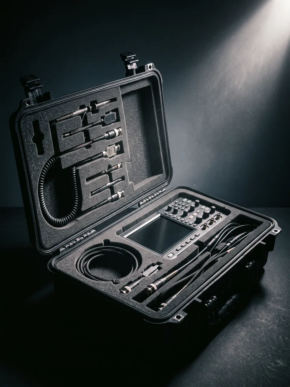
Marking on a socket case does two jobs: it helps the user find a target size quickly, and it makes counting executable. Socket sizes are normally quoted as across-flats dimensions, and within one set the increments may be only a millimetre or two while the items look nearly identical, so size marking must be legible, wear-resistant and readable in low light.
The best position is beside the cavity rather than in it. Marking inside the cavity floor is protected from abrasion but is hidden whenever the tool is in place, whereas marking beside the cavity stays visible and can be checked before insertion. Printing should use oil-resistant and abrasion-resistant processes such as in-mould printing, laser marking or durable labels. Inkjet printing and ordinary adhesive labels blur quickly in an oily environment and are unsuited to long service.
Functional items such as the ratchet and extensions need more than a name: the drive square size of the ratchet head, the length of the extension, and the type of driver bit all matter, especially in a mixed set where similar-looking pieces are easily swapped. Where one case contains two different drive series, the marking system must separate them unambiguously, for example with two base colours or clear zoning. Confused marking is a common cause of misplacement, misuse and counting error, and its cost is generally underestimated.
External marking forms the second layer: set name, drive size, piece count and an identification number. A piece-count marking is valuable for management, because counting begins by confirming the total and then locating the gap, which shortens the exercise further. An external number distinguishes tool sets within a crew, which matters as soon as several cases coexist.
Inspection and Acceptance: Drop, Vibration and Cycle Testing
Acceptance for a socket case should be built around tests that map directly onto function. The first covers loading and location. Insert every item on the specified tool list, checking that each matches its cavity, enters freely and does not rock. Then run an inverted tap test to confirm nothing leaves its cavity, followed by an inverted shake test to confirm nothing migrates inside one.
The second covers open-close cycling. With the case fully loaded, cycle the lid repeatedly, checking for hinge loosening, displacement of lid compression elements, and change in latch closing force. The cycle count should reflect real usage, translating daily operations across the expected service life. This test exposes wear-related problems that appear only after sufficient repetition.
The third covers vibration and transport simulation. Subject the loaded case to transport-profile vibration, or an equivalent long-distance transit simulation, then check for liner compression marks, tool displacement and loosened fasteners. This matters particularly for socket cases, because metal parts in sustained vibration undergo fretting that damages mating surfaces over time.
The fourth covers drop testing. Drops are normally applied in different attitudes, base, edge and corner, confirming that the shell does not crack, the liner does not fracture and tools do not leave their locations. Because drop testing damages tools, it is usually performed at type-test stage, and substituting ballast weights for the real tools is common. Ballast mass distribution should approximate the real tools, or the loading on liner and base becomes unrealistic. Other verification methods relating to stacking and transport appear in what toolbox stackable design is for. Acceptance conclusions should record test conditions, sample count and verdict as traceable documentation.
Failure Modes and Procurement Traps
Failures in socket cases follow a fairly fixed sequence. Cavity relaxation comes first, showing as tools that rock and reduced insertion resistance; the usual causes are permanent compression set in the foam or oil ingress softening it. Lid compression failure follows, showing as tools shifting in transit even with the lid closed, caused by ageing or displacement of the compression material.
The third stage is shell deformation with liner misalignment, showing as difficulty closing the lid, higher latch force and loss of parallelism between liner face and lid interior. The fourth stage is functional failure of hinges and latches, including worn hinge pins, fractured stops and failed latch springs, which directly undermines closure reliability and therefore disables the anti-scatter design entirely. The fifth stage is corrosion, typically after prolonged damp storage, indicating that the case's moisture strategy or the way it is used does not match the environment.
Procurement traps centre on leaving functional requirements unstated. The first omission is specifying liner material without density and compression ratio, which lets feel and grip vary noticeably between batches. The second is failing to tie cavities to the tool list, producing cases where individual tools will not fit or rock. The third is not defining how lid compression will be verified, leaving anti-scatter capability at the level of appearing to exist. The fourth is omitting load test requirements for the shell and judging quality from static appearance only. The fifth is neglecting marking deliverables, including abrasion resistance of internal size marking, piece-count marking and the numbering scheme.
The sixth is excluding liners and compression elements from spare parts supply. These are high-turnover components, and a supplier who offers only complete cases leaves the buyer replacing whole units after a few years. With all six closed, and with prototype test data serving as the acceptance baseline, socket case purchasing becomes a verifiable engineering exercise.
Frequently Asked Questions
Q: Should a socket case liner be a fully milled cavity or a universal divided tray? A: It depends on how stable the tool list is and how much positional accuracy matters. A fully milled liner machines a cavity to the measured size of each tool, so every item has one unique location with its own insertion feel and resistance, giving the best counting efficiency and the strongest anti-scatter performance; the cost is that the liner is bound to one tool list, so a change of model or quantity requires a new liner, with higher tooling investment and a longer lead time. A universal divided tray uses rectangular compartments or bar slots with elastic restraint, offering versatility, low cost and tolerance of tool changes; the cost is poor positional accuracy, tools that rock in mismatched compartments and migrate in transit, and no visual signal of a missing item. A practical test is change frequency: a stable list used intensively justifies full milling, while a frequently revised or temporary kit suits a tray. A hybrid inside one case also works well, putting high-frequency and heavy items in milled cavities while occasional accessories go into divided zones, combining accuracy with flexibility.
Q: Tools scatter when the case is carried. Where should the fix start? A: Work from the outside inward. Begin with lid compression: close the lid, invert the case and tap the base, then open and look for tools that have left their cavities. If any have, compression is insufficient or the elements are misplaced; increase compression material thickness, switch to elastic elements, or add local pads above the tools most likely to lift. Next check cavity compression ratio. Visible clearance between tool and cavity means the cavity is oversized or the foam has taken a permanent set; the first requires a new liner, the second is material ageing and also requires replacement. Third, review opening attitude and hinge stops: an excessive opening angle or a rearward shift in the loaded centre of gravity lets tools topple as the lid opens, which can be improved by adjusting the stop angle or relocating heavy items. Fourth, review practice, including whether the case is carried with the lid unlatched or stacked in a high-vibration location. Most scatter problems resolve within the first two steps; only when cavity and compression are both sound do more elaborate measures such as section lids or mechanical catches become worthwhile.
Q: How should liner foam density be chosen, and is harder always better? A: Harder is not automatically better; density balances grip against retrieval feel. Higher density gives stiffer cavity walls with greater clamping force, so heavy items resist migration and cavity geometry holds its shape longer, which suits large, regularly shaped tools. But high-density foam feels firm, raises insertion and extraction resistance, can damage small or complex items, and adds mass. Low-density foam feels soft, retrieves easily and weighs less, but clamping force is weak and permanent compression set develops sooner, leaving cavities loose. Standard practice differentiates by location: heavier-duty or heavier-item cavities use higher density, or a PE and EVA laminate; general cavities use medium-density EVA; small and delicate cavities use lower density to reduce insertion stress. Selection should start from a machined sample that is tested for insertion and extraction force within an acceptable band, rather than relying on a material supplier's data sheet alone, because the finished feel depends on cavity geometry as much as on density.
Q: Does a socket case need moisture and corrosion protection, and does desiccant actually help? A: Yes, but each measure has defined limits. Sockets, ratchets and driver bits all corrode after long exposure to damp conditions or temperature cycling, particularly during humid seasons and in coastal environments. Desiccant adsorbs moisture from the enclosed air and lowers relative humidity at low cost and with simple handling, but its capacity is finite, it must be replaced or regenerated once saturated, and its effective life depends directly on how well the case seals. VCI materials form an extremely thin protective layer on metal surfaces to suppress corrosion and suit relatively enclosed spaces, but they are sensitive to contamination, perform poorly if tools carry moisture or corrosive soil, and also expire. The practical conclusion is that if the case itself seals well, with a gasket and compression latches, both desiccant and VCI stay effective for a long time; if the case leaks, using either alone gives limited and unpredictable results. Confirm the case protection rating before deciding on the moisture strategy, and put consumable replacement intervals into the maintenance plan.
Q: How can a missing piece in a set be made obvious at a glance? A: There are three escalating levels. The first is one-to-one correspondence between cavity and tool, shaping each cavity precisely to its item so a full set looks orderly and an absence produces a clear visual gap; this requires the liner to be bound to the tool list, which a universal tray cannot achieve. The second is high-contrast marking, using a base colour inside cavities that contrasts strongly with the tools and keeping cavity edges crisp, so a scan from above reveals gaps within seconds; marking the size beside each cavity also supports confirmation before insertion. The third is a structured counting routine, numbering cavities in size order with the order printed along the liner edge so counting becomes a sequential scan, supplemented where needed by a checklist card matching the cavity layout on the liner or lid interior. Note that this capability decays with liner wear: as cavities enlarge and tools sit off position, visual orderliness drops and gaps stop standing out. When tools begin to rock noticeably, the liner should be scheduled for replacement rather than kept until it fractures.
Q: How should a drop test be run so that it actually means something? A: Effectiveness depends on whether the test case reflects real use, not on dropping the case once. Begin by fixing height and attitude. In practice a case may land on its base, an edge or a corner, and each attitude tests a different failure mode, so they normally need separate trials. Next fix the loading state: a loaded drop and an empty drop load the structure completely differently, and in a loaded drop heavy items generate inertial force inside their cavities that can crush the liner or drive the base outward, so the test should be run loaded. Third, decide on substitution. Using real tools damages them, so ballast weights are common, but their mass distribution must approximate the real tools or the loading on liner and base becomes unrealistic. Fourth, define pass criteria in advance, covering shell cracking, liner fracture, tool displacement and latch reliability, and write them down before testing so that judgement is not negotiated afterwards. Fifth, re-check after testing, because some damage is not immediately visible; a slightly deformed hinge or a hidden crack in the liner will develop during subsequent use.
Q: Which load-bearing details are most often overlooked in shell design? A: The first is load distribution. Socket set mass is not uniform; it concentrates in the densest socket cluster and at the ratchet position, so a base sized for uniform load deflects in those areas, takes a permanent set, and destroys liner flatness and positional accuracy. The correct answer is ribs or thickened zones under those clusters to spread the load. The second is handle root loading: with a full load the roots carry far more than the rest of the shell, requiring a thickened zone or internal reinforcement plus alignment of the working load direction with the shell's primary load path. The third is the effect of deflection on closure: if the shell flexes under load, the fit between lid and liner changes, redistributing compression and leaving some areas unpressed, which is why load design and anti-scatter design belong in the same iteration. The fourth is dynamic load in a drop, which runs several times the static weight, with heavy items generating inertial force against liner and base, requiring deformation space or a cushioning layer beneath cavity floors so the shock does not pass straight into the shell structure.
Q: What are the most common traps in volume purchasing of socket cases? A: Most traps reduce to functional requirements never making it into the contract. The first is naming a liner material without density or compression ratio, letting feel and grip vary between batches in a way users notice but struggle to document. The second is failing to tie cavity geometry to the tool list with an acceptance method, producing deliveries where individual tools will not fit or rock, with both sides disagreeing on what counts as conforming. The third is not defining how anti-scatter capability will be verified, so a supplier only has to demonstrate that foam exists inside, leaving the real performance untested. The fourth is omitting load test requirements and judging quality from static appearance and a manual lift. The fifth is leaving out marking deliverables, including abrasion resistance of internal size marking, piece-count marking and numbering. The sixth is excluding liners, compression elements and hinges from spare parts supply, so after several years the user can only replace whole cases. Avoiding these requires converting functional requirements into testable clauses, retaining prototype samples and test records as the acceptance baseline, and agreeing a supply period and pricing mechanism for wear parts.
Q: How should a socket case be maintained, and how often do liners and hardware need replacing? A: Maintenance should protect positional accuracy and closure reliability rather than appearance. After each use, clear metal swarf and dust from the cavities, because embedded debris grinds against the foam surface during insertion and accelerates cavity wear; remove oil with a neutral detergent applied locally, avoiding strong solvents that attack most foams and sealing materials. Store the case closed in a dry environment, since prolonged damp storage affects both metal parts and liner. For replacement intervals, judge the liner by function rather than calendar: once tools rock noticeably in their cavities, insertion resistance drops sharply, or a missing item no longer leaves an obvious visual gap, the liner is due for replacement, and under normal use that point depends heavily on foam density, cycle count and cleaning discipline. Lid compression elements are due when an inverted tap test still shifts tools, or when the compression material is visibly flattened, cracked or displaced. Hinges and latches are safety-related: replace them as soon as they loosen, rattle, change closing force noticeably or lose spring function, because either failure disables the anti-scatter design outright. A simple usage record linking inspection results to replacement actions keeps a socket case performing steadily across its whole service life.