

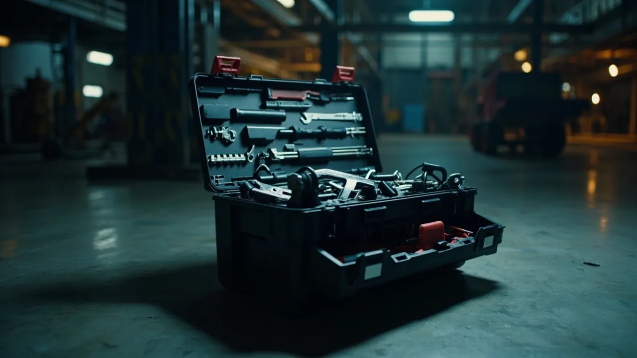
Short answer: the best interior layout is not the one with the most compartments. It is the one where every tool has a single, dedicated position you can reach in under two seconds, while wasted volume is driven to a minimum. Those two clauses correspond to two measurable goals: the shortest retrieval path (every tool comes out in one motion, without moving anything else and without hunting), and the highest fill ratio (the share of usable case volume actually occupied by the tools). More compartments lower the fill ratio, because every divider adds thickness and every cell needs clearance; fewer compartments lengthen the retrieval path, because tools end up piled together. The genuine optimum sits where those two curves cross, and that crossing point is determined entirely by your tool list. There is no universal best number of cells.
So the method in this article works backwards from the tool list, rather than buying a case with whatever liner it happens to ship with and then cramming tools into it. Four steps: build the list, layer by weight and frequency, derive the module and cavities from actual dimensions, then validate against fill ratio and retrieval path. Along the way the article compares layer structures, explains how to define a module and close the dimensional chain, gives practical values for cavity depth and layer height, weighs interior materials against each other, sets out the ballast and frequency matrix, covers custom cavities for awkward tools, describes modular expansion, quantifies space utilisation, lists six design errors that waste space, and closes with consistency control from prototype to production.
Table of Contents
- Start with the conclusion: retrieval path and fill ratio
- Backwards from the tool list: a four-step layout method
- Layer structures compared: trays, drawers, clamshells and hanging panels
- Module and dimensional chain: defining cell width from the smallest unit
- Cavity depth and layer height: avoiding the fits-but-you-cannot-grab-it trap
- Interior materials: contoured EVA, EPE separators, dividers and straps
- Heavy low, frequent high: the ballast and frequency matrix
- Custom cavities for awkward tools: drills, spanner sets and instruments
- Modularity and expandability: dividers, rails and accessory systems
- Quantifying utilisation: how to calculate fill ratio and retrieval path
- Six design errors that waste space
- Prototype to production: interior consistency and acceptance
- FAQ
- Closing remarks and related reading
Start with the conclusion: retrieval path and fill ratio
Splitting "a good layout" into two measurable indicators is what makes the discussion useful.
Indicator one: retrieval path, counted in motions. Definition: from the moment the case is fully open, how many motions does it take to get a given tool out and ready? The ideal is one: reach in and take it, with no second step. Two is acceptable — lift a tray, then take the tool. Three or more (move something else first, hunt for it, unfasten a strap) means the design is wrong. Retrieval path is not only about efficiency. In breakdown work, live working or work at height, every extra motion adds risk. In everyday work, a long retrieval path causes people to stop putting tools back — which is the real reason interiors degrade into chaos within weeks.
Indicator two: fill ratio, or space utilisation. Definition: the volume occupied by the tools' outer envelopes divided by the usable volume of the case. "Usable" means after deducting liner wall thickness, divider thickness and structural dead corners. Typical ranges, as field estimates:
- loose, unlined stowage: apparently high, but tools press on each other, retrieval paths are long and damage rates are high, so it is not real utilisation;
- generic grid compartments: moderate, with losses from divider thickness and from small parts sitting in oversized cells;
- contoured EVA: usually the highest, because cavities follow the tool outline, clearances can be held tight, and the depth dimension can be used three-dimensionally.
The two indicators trade against each other. Finer cells shorten the retrieval path but raise the share taken by dividers and clearance, lowering fill ratio. The optimum appears when every tool has one dedicated position whose size closely matches its outer envelope — which is exactly the logic of a contoured liner, and exactly why it beats buying a handful of plastic divider boxes.
In one sentence: the purpose of compartmentalisation is not to cut the space up; it is to give every tool a defined, close-fitting, reachable home.
Backwards from the tool list: a four-step layout method
Step one: build the complete list and record four fields per item. Do not work from memory. Tip the tools onto a bench and record them one at a time.
| Field | What it means | Used for |
|---|---|---|
| --- | --- | --- |
| Name | Unique identifier, never "the small one" | Labelling and inventory |
| Envelope dimensions (L × W × H) | Including handles and protrusions | Cavity sizing |
| Weight | Measured | Layer and ballast decisions |
| Retrieval frequency | High / medium / low | Vertical position |
The classic error here is recording only the "functional" dimensions and ignoring protrusions. A screwdriver may have a 200 mm shaft but a 32 mm handle diameter. An adjustable spanner may be 250 mm long but 70 mm across when the jaw is open. Cavities must be cut to the maximum envelope, or you get cases where the tool goes in but the lid will not close, or goes in but will not come out.
Step two: first pass at layering, by weight times frequency. The rule is simple: heavy low, frequent high. Spread as a matrix:
| High frequency | Medium frequency | Low frequency | |
|---|---|---|---|
| --- | --- | --- | --- |
| Heavy | Upper layer, outer edge (needs judgement) | Middle | Bottom |
| Medium | Upper | Middle | Lower middle |
| Light | Top | Upper | Any remaining space |
The "heavy plus high frequency" cell is a genuine conflict: heavy items low lower the centre of gravity and reduce carrying effort (see balancing weight and handle on a portable toolbox), while high frequency items high shorten the retrieval path. The resolution is to put such tools in an easy-access zone on the bottom layer — near the opening side, retrievable without removing anything else — rather than simply burying them at the bottom.
Step three: cluster by envelope dimensions and define the module. Group tools whose dimensions allow them to share a cell width: various sizes of slotted and cross-point screwdrivers, hex key sets, and so on. This step sets the number and position of dividers.
Step four: draw the layout and validate both indicators. Sketch each layer, then check item by item: is the retrieval path one motion, is the fill ratio acceptable, is the centre of gravity central, and does any tool need another moved before it can be taken out? Where there is a conflict, go back to step two.
Do those four steps and you end up not with "a rough idea about compartments" but with a layout drawing you can hand straight to a liner supplier.
Layer structures compared: trays, drawers, clamshells and hanging panels
Five mainstream structures exist, each with clear boundaries of application.
1. Fixed multi-tray, lift-up type. Opening the case raises the upper tray on linkages or folds it out to both sides, exposing the space below. This is the classic multi-layer toolbox. Advantages: every layer presented at once, excellent visibility, short retrieval path (usually one or two motions), mature and reliable mechanism. Drawbacks: linkages consume volume; tray walls and ribs cost space; the number of layers is limited by height, typically two or three. Best for: hand-tool-dominated kits with many item types where you want to see everything at a glance.
2. Drawer type. Each layer is an independent drawer pulled out on its own. Advantages: accessing one layer does not disturb the others; deeper layers are possible; ideal for small parts (screws, terminals, drill bits, blades). Drawbacks: runners and side walls consume noticeable volume; drawers can slide open under transport vibration unless locking is reliable; higher cost. Best for: small-parts-heavy kits, fixed locations (benches, service carts), and cases that are not constantly carried around.
3. Clamshell with internal divisions. Top and bottom shells open flat, each carrying fixed or semi-fixed divisions. Advantages: simplest structure, lowest cost, no moving parts, highest reliability; good for flat tools and frequently used items. Drawbacks: few layers, usually one or two per side; poor utilisation of deep space. Best for: small sets of flat tools, and situations where reliability matters more than flexibility.
4. Hanging panels. Tools hang from perforated panels or hooks on the lid interior or inside the body. Advantages: shortest possible retrieval path, best visibility, nothing occludes anything else; good ventilation, less moisture trapping. Drawbacks: tools need hanging holes or add-on clips; they can swing and knock together during transport unless positively retained; volume utilisation is usually lower than a contoured liner. Best for: frequently used hand tools, situations requiring instant identification, and humid environments where avoiding prolonged tool-to-foam contact helps.
5. Contoured liner (EVA or PE, single or multi-layer). Cavities cut to the tool outline, one per item, stackable in layers. Advantages: highest fill ratio, most positive retention (no movement, constant centre of gravity), precise control of layer height, best appearance and professionalism; best protection for precision and fragile items. Drawbacks: higher custom cost; a changed tool list means a new liner; unfriendly to "just one more tool today". Best for: precision tools, instruments, dedicated tool sets, and kits managed over the long term.
| Structure | Fill ratio | Retrieval path | Retention | Change flexibility | Cost |
|---|---|---|---|---|---|
| --- | --- | --- | --- | --- | --- |
| Fixed multi-tray | Medium | Short (1 to 2) | Medium | Medium | Medium |
| Drawer | Medium | Short (1 to 2) | Medium to high | Medium | Medium to high |
| Clamshell | Medium | Short (1) | Medium | Low | Low |
| Hanging panel | Low to medium | Shortest (1) | Low to medium | High | Low to medium |
| Contoured liner | High | Short (1) | High | Low | Medium to high |
Real projects often combine them: a contoured EVA base holding heavy and precision tools, a middle layer of adjustable dividers for everyday items, and a hanging pocket or mesh pouch inside the lid for flat items and documents. That combination balances fill ratio against flexibility well.
Module and dimensional chain: defining cell width from the smallest unit
"Module" is the concept that makes an interior both tidy and efficient. The method:
Define a minimum module M. Find the envelope width of the smallest unit that needs its own cell — the smallest screwdriver, the smallest hex key — add the clearance needed to get hold of it, and call the result the minimum module M. Clearance rule of thumb: leave enough room on each side for fingers to enter and pinch the tool, generally not less than the order of 10 mm; tools that must be grasped with the whole hand need more.
Make every cell width an integer multiple of M. With M = 20 mm, cell widths become 20, 40, 60, 80 mm. Dividers standardise, the layout looks orderly, and later changes are easy.
Verify the dimensional chain. For each layer: sum of cell widths + sum of divider thicknesses + two side liner walls = internal clear width. This chain must close. Get any term wrong and the last divider will not fit, or you are left with an unusable sliver. Write it out explicitly on the drawing:
`` Internal clear width = SUM(cell widths) + SUM(divider thicknesses) + 2 x side liner thickness ``
Handling the remainder. If, after closing the chain, some width remains — say 15 mm — do not leave it as a narrow, deep, useless slot. Three options:
- Merge it into the neighbouring cell and use the extra width for a slightly larger tool.
- Turn it into a shallow flat channel for blades, bits or cards.
- Eliminate it at source by adjusting the case width during selection.
Depth works the same way. Each cell's depth should follow the longest tool assigned to it rather than being uniform across the layer — and this is precisely the advantage of a contoured liner: it can produce different cavity depths within the same layer, whereas divider systems generally give a uniform cell depth.
| Parameter | How to define it | Typical value |
|---|---|---|
| --- | --- | --- |
| Minimum module M | Smallest unit envelope width plus two clearances | Set by the tool list |
| Retrieval clearance | Fingers can enter and pinch | At least about 10 mm per side |
| Divider thickness | Set by material and stiffness | A few millimetres for plastic, thicker for foam |
| Cavity depth | Maximum tool thickness plus floor margin | Must not foul the lid |
| Layer height | Tallest tool in the layer plus clearance above | Avoid interference between layers |
Cavity depth and layer height: avoiding the fits-but-you-cannot-grab-it trap
This is the most common and most overlooked failure mode in interior design: the tool fits in plan view but cannot actually be removed, because depth or layer height is wrong.
Trap one: cavity too shallow, the tool stands proud. The tool sits above the liner surface, so the lid presses on it — or fails to reach the sealing face. Fix: cavity depth = maximum tool thickness + floor margin, the margin keeping the tool off the case floor and absorbing tolerance.
Trap two: cavity too deep, invisible and unreachable. The tool sinks completely and fingers cannot grip it. This is the opposite extreme and just as common. Fix: do not make the cavity much deeper than the tool is thick; where a tool sits fully below the surface, provide a finger notch or leave one end of the cavity open. A finger notch is the simplest effective remedy: a semicircular or rectangular cut at one end or side of the cavity, letting a finger in to lever the tool up. Its size should be comparable to a finger width.
Trap three: insufficient layer height, interference between layers. Tools in adjacent layers foul each other vertically — a drill with a tall body in the lower layer meeting the tray above. Fix: run a vertical projection check on the drawing. Project every layer's tool outlines onto a single plane and look for overlaps where the height sum exceeds the clear height between layers.
Trap four: accumulated tolerance at closing. In multi-layer builds, per-layer tolerances add up. Design to "just fits" and production units will be hard to close. Fix: allow an accumulated tolerance margin in layer height, and prove lid closure with real tools at the prototype stage.
Trap five: ignoring liner compression. Foam liners compress somewhat under sustained load, so cavities become shallower and tools loosen. Fix: choose a low compression-set material (assessable against the GB/T 7759 series) and allow a little margin in the design.
Practical recommendation. Once the drawing is settled, build a rough mock-up — scrap foam board or thick card cut to the drawing — load it with the real tools, take each one out, and close the lid. Then cut the real liner. This costs almost nothing and catches nearly all the errors that would otherwise be unrecoverable later.
Interior materials: contoured EVA, EPE separators, dividers and straps
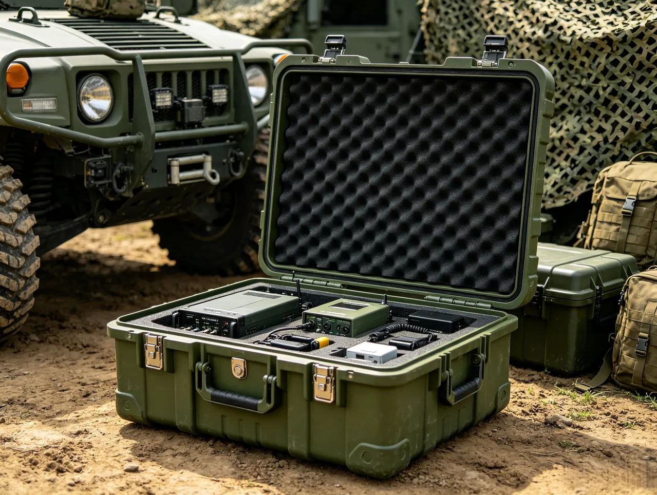
Material and structure decide retention, fill ratio and long-term stability.
EVA (ethylene-vinyl acetate foam). Density typically runs from a few tens to somewhat over a hundred kilograms per cubic metre depending on grade. It is closed-cell, resilient, can be flocked, and machines cleanly by CNC or die-cutting into accurate contoured cavities with good wall verticality and tidy edges. Water absorption is low, suiting damp environments. Best for: precision tools, instruments, dedicated sets, and anywhere appearance and professionalism matter. See the advantages of EVA liners. Watch points: higher density gives better support and abrasion resistance at the cost of weight and price; density that is too low lets cavity edges collapse and tools work loose.
EPE (expanded polyethylene). Low density, light, cheap, excellent cushioning. But its open-cell tendency is greater than EVA's, so it picks up more moisture in sustained humidity; the surface frets and pills relatively easily; CNC surface finish is less refined than EVA. Best for: general cushioning, separators for large tools, cost-sensitive applications with modest precision demands. See the EPE versus EVA comparison.
Adjustable divider systems (plastic or foam). Slots and dividers combined into configurable cells. Advantage: flexible, re-combinable when the tool list changes. Drawbacks: slots and dividers consume volume, fill ratio is below a contoured liner, and small parts still rattle inside their cell. Best for: frequently changing tool lists and layouts adjusted in the field.
Elastic straps and hook-and-loop fixing. Tools strapped to a base board or tray. Advantages: cheap, extremely flexible, consumes no volume. Drawbacks: retention is only moderate, especially for small and slender items, and elasticity decays with use. Best for: supplementary retention of large items such as drills and spanners, or as a back-up to a contoured liner.
| Interior option | Fill ratio | Retention | Change flexibility | Moisture behaviour | Cost |
|---|---|---|---|---|---|
| --- | --- | --- | --- | --- | --- |
| Contoured EVA | High | High | Low | Good | Medium to high |
| EPE separators | Medium | Medium | Medium | Fair | Low |
| Adjustable dividers | Medium | Medium | High | Depends on material | Medium |
| Elastic straps | High | Low to medium | Very high | Good (no contact face) | Low |
| Combined scheme | Medium to high | Medium to high | Medium | Good | Medium to high |
Selection logic is treated more systematically in how to choose toolbox interior foam. One addition specific to compartment design: use one interior scheme per layer wherever possible. Mixing them produces inconsistent layer heights, makes the lid hard to close, and complicates fabrication and assembly.
Heavy low, frequent high: the ballast and frequency matrix
The basic rules were given above; three practical details follow.
Detail one: design an easy-access zone on the bottom layer. The bottom should not be "whatever is buried deepest". Either let the bottom tray lift or slide out as a unit, or place heavy items where they are directly visible once the case is open. In a lift-up multi-tray design the bottom becomes visible once the linkage raises the trays, giving a retrieval path of two — lift, then take — which is acceptable.
Detail two: lateral ballast and carrying. If the case is carried one-handed, heavy items should sit on the side nearest the body (see balancing weight and handle on a portable toolbox). This looks to contradict "keep the centre of gravity central", but they are different axes: vertically, heavy-low lowers the centre of gravity; horizontally, heavy-near-the-body shortens the lever arm. No conflict.
Detail three: symmetry and long-term distortion. For two-handed carries and rolling cases, keep the load laterally balanced. Chronic one-sided loading distorts the shell, wears wheels unevenly, loads hinges asymmetrically and compresses one side of the liner faster. Do the weight distribution arithmetic on the drawing: note the weight in each cell, sum left and right halves separately, and check that the difference stays within a modest share of the total.
One frequently missed item: batteries and chargers. Battery packs are often heavier than the tool itself, and there is usually more than one. List them separately and include them in the ballast calculation — plenty of layouts only discover at trial fitting that two batteries in the base have made one end heavy.
Custom cavities for awkward tools: drills, spanner sets and instruments
Standard rectangular cavities cannot cope with three categories, and each needs its own approach.
Category one: power tools with protruding handles (drills, angle grinders, rotary hammers). Their shape is an L or T of body plus handle, which no rectangle accommodates. Design points:
- cut the cavity to the real outline, handle and chuck included;
- the handle is a natural grab point, so orient it upward with room to close a hand around it;
- leave the battery position empty or give it its own cavity, since many operators prefer to store batteries separately from the body for transport safety;
- the chuck is the most vulnerable part, so leave generous clearance there to avoid knocks that degrade accuracy.
Category two: grouped tools (spanner sets, socket sets, bit sets, hex key sets). The principle is serial arrangement: order by size, one cavity per size, and mark the size beside or beneath each cavity. The payoff is that a missing item is obvious at a glance — the same logic as a shadow board — and the retrieval path is one.
- Spanner sets: arrange by jaw size; cavities can be cut as a slanted comb to save length.
- Socket sets: usually held on a dedicated rail or magnetic strip fixed into the cavity.
- Bit sets: small cells or elastic slots that keep them together and stop them scattering.
Category three: precision instruments and fragile items (calipers, micrometers, distance meters, probes, lenses). The principle is individual cavity plus cushioning plus isolation:
- never share a cell with metal tools, to avoid knocks;
- protect measuring faces with a flocked surface or soft pad;
- the cavity should fit closely without compressing — too tight deforms the instrument over time and affects accuracy;
- for instruments needing shock protection, see shockproof cases for precision tools.
Category four: consumables and small parts (screws, terminals, blades, washers, adhesives). The principle is containerisation: small boxes, pouches or divided trays, placed as a single unit into a cavity. Never loose. Loose small parts mix during transport and produce a fill ratio that looks good but is unusable. Containers should be transparent or labelled.
Modularity and expandability: dividers, rails and accessory systems

Tool lists change; liners cannot be recut every time. Modularity reconciles custom precision with change flexibility.
Level one: adjustable dividers in standard slots. Pre-set slots at a standard pitch in the base or tray; dividers plug in and move as needed. Cheap to change. Drawbacks: slots consume volume, and small parts still rattle between divider and slot.
Level two: standardised storage modules. Uniform external dimensions for boxes or cells, combined as needed to fill the case. Advantages: a module can be taken out and used on its own — carry only one into the job — and modules interchange between cases. Drawbacks: double walls cost volume, so fill ratio is below direct cavity cutting.
Level three: rail or clip-on systems. Rails or anchor points on the walls or liner, with hooks, pouches, boxes and clips attached as needed. Highly expandable, but the structure is complex and costly, and accessories must lock positively so they cannot shake off in transit.
Level four: the hybrid, which is usually the right answer. Contoured EVA on the bottom layer for the unchanging core tools; adjustable dividers or standard modules above for the parts that change. This keeps the retention and fill ratio where they matter and leaves room to adapt. It is also the mainstream recommendation in modular interior design.
Two constraints must be respected in any modular system:
- Modules must not move when the lid is closed. Anything free to shift during transport generates impact loads and noise; positive location or locking is mandatory.
- Module weight and ballast must be calculable. The cost of modularity is that ballast changes with configuration, so mark the weight on each module and check lateral balance and centre-of-gravity height once for each common configuration.
Quantifying utilisation: how to calculate fill ratio and retrieval path
Fill ratio.
`` Fill ratio = SUM(envelope volume of each tool) / usable case volume x 100% ``
where:
- tool envelope volume = length × width × height taken over the maximum envelope, handle and protrusions included. For complex shapes, approximating with a minimum bounding box is acceptable.
- usable case volume = internal clear length × width × height, after deducting wall and liner base thickness. For multi-layer builds, calculate per layer and add them up, deducting the volume taken by dividers, tray walls and linkage mechanisms.
The value of this metric is comparison, not absolute judgement. Take one batch of tools and trial-fit three schemes — loose, generic grid, contoured — and compute three fill ratios. The difference is immediately visible, and it is the direct argument for investing in a contoured liner, which typically scores materially higher than a generic grid.
Retrieval path. Score every tool:
- 1: taken straight out once the case is open, with nothing in the way and nothing to move;
- 2: requires lifting one tray or opening one cover first;
- 3: requires moving another tool first;
- 4: requires hunting or unfastening something.
Compute the average and count how many tools score 3 or more. A reasonable acceptance target: average not above 1.5, and zero tools scoring 3 or above. Any tool at 3 or above needs relocating — either it is genuinely low frequency, which can be accepted, or the design is wrong and must change.
Two supporting metrics.
- Centre-of-gravity offset: the horizontal offset of the loaded centre of gravity from the geometric centre; smaller is better. For one-handed carrying, the centre of gravity should also sit close to below the handle.
- Left-right weight difference: |left half − right half| / total weight, kept to a small fraction, to avoid chronic off-centre loading.
Write those four metrics into acceptance criteria and interior design stops being "it feels about right" and becomes measurable, comparable and inspectable.
Six design errors that waste space
- Uniform cell depth regardless of tool thickness. Dividing the space into cells all the same depth wastes the depth dimension under shallow tools and refuses deep ones. Fix: group and layer by tool thickness, or use a contoured liner for varying depths within one layer.
- Cells that are too fine. Cutting the space into many small cells spends a noticeable share on dividers and clearance, and larger accessories no longer fit. Fix: merge with a module; only subdivide where mixing would lengthen the retrieval path or damage tools.
- Narrow, deep remainders. Imprecise dimensional arithmetic leaves a sliver that cannot be used. Fix: calculate the chain explicitly, then either merge the remainder into a neighbour, turn it into a shallow channel, or remove it when selecting the case.
- Ignoring protrusions. Cutting to the body dimensions and forgetting chucks, handles, open spanner jaws and caliper jaws. Fix: record maximum envelope dimensions at the list stage.
- Loose consumables. Screws, terminals and blades poured straight into cells: fill ratio looks high, but the space is unusable because retrieval is slow, parts mix and they spill. Fix: containerise, and plan a cavity for the container as though it were a tool.
- No provision for getting hold of things. Cavities cut so tight that tools sink entirely and fingers have nothing to grip. Fix: give every individually retrieved cavity a finger notch or an open end; for slender items, widen the cavity part-way along to form a finger channel.
| Error | How it wastes space | Direct consequence | Correction |
|---|---|---|---|
| --- | --- | --- | --- |
| Uniform depth | Wasted volume in depth | Low fill ratio | Layer by thickness or contour |
| Over-fine cells | Dividers and clearance dominate | Low fill ratio, inflexible | Module merging |
| Remainder slivers | Unusable volume | Low fill ratio | Dimensional chain check |
| Ignoring protrusions | Tool will not fit | Design rework | Record maximum envelope |
| Loose consumables | Illusory utilisation | Long retrieval path | Containerise |
| No retrieval provision | Tool cannot be removed | Poor user experience | Finger notches |
Prototype to production: interior consistency and acceptance
On custom liner programmes the biggest risk is not that the prototype is poor; it is that production does not match the prototype. The control points:
Prototype stage
- Fit with real tools, not substitutes. Tolerances, wear marks and label thickness all affect fit.
- Verify four actions: insert, remove, close the lid, and carry (lift the loaded case and rock it, checking for movement and noise).
- Verify extremes: does the tallest and thickest tool fit; does the longest tool work when laid diagonally.
- Photograph and archive with a version number as the baseline for production acceptance.
Production control points
- Material consistency: confirm density, hardness, colour and flammability class match the prototype. Ask for the material grade and density data; where fire performance matters, state the UL94 classification.
- Machining accuracy: agree tolerances on contoured cavity dimensions, marking critical cavities explicitly, and agree the sampling rate.
- Depth consistency: cavity depth is the parameter most prone to drift in production, so make it a priority inspection item; a depth gauge or a gauge block gives a fast check.
- Edge quality: surface finish from CNC, absence of scorching and burrs; for die-cut parts, whether edges are square and free of stringing.
- Assembly consistency: relative position of layers in a multi-layer build, how dividers are fixed, and the gap after closing.
- Packing and transport: whether the liner is crushed in its packaging, and whether permanent set develops after prolonged compression.
Writing the acceptance criteria. Specify in the contract:
- material grade and density range;
- dimensions and tolerances of critical cavities;
- cavity depth tolerance;
- no contact with tools after closing, and no interference with sealing face contact;
- with the case loaded and rocked in the specified manner, no perceptible internal movement;
- appearance requirements (no scorching, burrs or damage; acceptable colour variation);
- sampling rate and decision rules.
On OEM/ODM and volume liner programmes, JUNZHJIA normally asks the customer for the tool list plus physical samples or accurate 3D data, produces a layout drawing and a prototype for approval, and only then moves to production. Production is inspected against the sealed approved sample, and liner spares can be supplied by model so that a changed tool list means replacing one layer rather than the whole set.
FAQ
Q: Are more compartments always better? A: No. Compartments exist to shorten the retrieval path, but every added divider costs twice over: the divider itself occupies volume, and each cell needs clearance or the tool will not go in or come out. Past a certain fineness, those losses exceed the benefit and the fill ratio starts falling. The test is two metrics. Retrieval path: can every tool be removed in one or two motions without moving anything else? Fill ratio: what share of the usable case volume do the tools' outer envelopes actually occupy? If a tool already has a dedicated position and a retrieval path of one, subdividing further adds nothing. Efficient compartmentalisation is not "more"; it is "accurate" — one close-fitting position per tool, matched to its envelope, with no surplus clearance. That is exactly why a contoured liner usually beats a generic grid: its cavities follow the outline, so clearance can be driven down.
Q: Should I choose a contoured EVA liner or a divider system? A: It depends on how stable the tool list is and how positive the retention needs to be. Contoured EVA suits a fixed list, higher-value or awkwardly shaped tools, and long-term managed kits: highest fill ratio, a dedicated cavity per item, no movement in transit, constant centre of gravity, best protection for precision and fragile items, and the strongest professional appearance. The price is a higher custom cost and the need to recut when the list changes. Adjustable dividers suit lists that change often, layouts adjusted in the field, and tight budgets: very flexible, low cost. The price is volume taken by slots and dividers, small parts still rattling, and a lower fill ratio. A widely used middle path is the hybrid layout: contoured EVA on the bottom layer for the unchanging core (heavy, precision, sets), adjustable dividers or standard modules above for whatever changes. Also weigh the environment: in damp or dusty service, the low water absorption and wipeable surface of closed-cell EVA beat open-cell materials.
Q: Why does a tool go in but not come out? A: This is the most common interior failure, with three usual causes. Cavity too deep: the tool sinks entirely below the surface and there is nothing for fingers to grip. Keep the cavity no deeper than the tool is thick, and add a finger notch at one end or side, sized roughly to a finger, or leave one end of the cavity open so a finger can get under the tool. Cavity too tight: chasing "snug fit" by cutting narrower than the tool means the foam clamps it, which is very noticeable on smooth metal parts. Cut to the maximum envelope plus sensible retrieval clearance — generally not less than about 10 mm per side, more for tools grasped with the whole hand. Occluded layout: the tool is covered by another tool or by the layer above, so something has to be moved first. Check the retrieval path item by item on the drawing. One subtle extra: a cavity with near-vertical walls and considerable depth creates a wedging effect; a slight draft angle and a little relief at the bottom help a great deal.
Q: How many layers should a multi-layer toolbox have? A: There is no fixed number; it depends on case height, the thickness distribution of the tools and the retrieval path. A simple method: group the tools naturally by thickness — thin flat items, medium hand tools, taller power tools — and consider as many layers as you have groups; then check that each layer's clear height is sufficient (tallest tool in the layer plus clearance to the underside of the layer above plus accumulated tolerance margin); finally check that the retrieval path is acceptable. In practice, a medium case dominated by hand tools is usually best at two or three layers. Too few layers means tools pile up and the retrieval path lengthens; too many means insufficient clear height, interference between layers, and tedious opening. Two further constraints: tray walls, linkages and ribs consume volume, and the loss of usable volume rises with each additional layer; and linkages or drawer runners are moving parts, so more layers means more complexity, more cost pressure and lower long-term reliability. Where height is limited and tools are thick, reducing the number of layers and using a contoured liner to vary cavity depth within one layer beats forcing in a third layer.
Q: How do I stop tools from moving around? A: Movement means some degree of freedom between tool and cavity is unconstrained, so the job is to remove those freedoms. Four methods, usable in combination. First, contoured cavities: cut to the tool outline, with walls constraining horizontally and the floor supporting vertically. This is the most complete solution and suits precision and valuable items. Second, depth matching: cavity depth slightly less than or equal to tool thickness, so that once closed the layer above, or the lid, applies light pressure and constrains vertically. Keep that pressure modest, or it accelerates liner compression set and can damage the tool. Third, elastic retention: straps, hook-and-loop or elastic slots, good for large and irregular items; the drawback is that elasticity decays, so inspect and replace periodically. Fourth, infill: small foam blocks, filler strips or adjustable dividers to take up remaining space, suited to changing lists. Verification is simple: load the case, lift it, rock it gently and apply a few small vertical shakes; there should be no perceptible movement and no knocking. Remember that movement is not merely noise: it shifts the centre of gravity, damages tools through mutual impact, and accelerates liner wear.
Q: Do liners loosen with age, and how can I extend their life? A: They do. Foam liners undergo compression set under sustained load and environmental exposure, which shows up as shallower cavities, poorer wall recovery and tools that fit loosely. Delay it on four fronts. Material: choose a low compression-set grade (assessable against the GB/T 7759 series) with a moderately high density for better recovery and abrasion resistance. Design: avoid keeping the liner in an over-compressed state, avoid very deep cavities that leave side walls permanently stressed in bending, and avoid sharp tools bearing directly on the cavity floor. Use: avoid prolonged storage at high temperature or in direct sun — heat accelerates ageing, a topic also covered in summer heat and toolboxes — avoid contact with oils and solvents, since most foams are sensitive to them, and clean off dust and metal swarf regularly, because particles embed in the walls and accelerate wear. Maintenance: include the liner in periodic inspection and replace once cavities are visibly slack, edges have collapsed or the material is chalking. Ask suppliers for a recommended replacement interval and spares availability, and build that into the cost model rather than buying in an emergency.
Q: What if the tool list changes — does the liner have to be redone? A: It depends on the scale of the change and the interior scheme; there are usually three levels of response. Small change, one or two additional small tools: cut a local cavity into the existing liner, or fill the gap with a small foam block or an elastic strap; if the original design left a spare position, simply use it — which is why the first design should deliberately leave one or two spare positions in a secondary area. Medium change, some tools swapped or sizes altered: with a contoured liner you usually recut only the affected layer rather than the whole set, which is a real benefit of layered design; with a divider system you just re-combine, at almost no cost. Large change, the tool category changes entirely or the case is repurposed: run the four-step method again — list, layer, module, validate — redesign and re-prototype. To reduce the cost of this, adopt a hybrid layout from the start: contoured base for the core tools, adjustable dividers or standard modules above for the parts that change. Modular approaches — standard-size storage units, rail-mounted accessory systems — also cut change costs substantially; see modular interior design.
Q: How should power tools and batteries be stowed? A: Three principles. First, separate the battery or fix it positively. The tool body usually goes in a contoured cavity cut to the real body-plus-handle outline, oriented with the handle up for easy grabbing and with clearance around vulnerable parts such as the chuck. Batteries are better in their own cavity than fitted to the tool: a fitted battery enlarges the envelope, shifts the centre of gravity, and creates a safety question if something presses the trigger in transit. Second, count batteries in the ballast calculation. Packs are often heavier than expected and there is usually more than one, so list their weight separately and include it in layering and lateral balance. Plenty of layouts only find at trial fitting that two batteries in the base have made one end heavy. Third, consider temperature and ventilation. Lithium cells are heat-sensitive, and long storage in direct sun or in a hot sealed box accelerates ageing, so avoid prolonged exposure (see summer heat and toolboxes), and where conditions allow consider a case with a waterproof vent to equalise pressure. Where the industry requires it, state a flammability class for liner and shell (referencing UL94) and provide a dedicated stowage position for charger cables so they are not crushed or left loose.
Q: How do I judge whether my interior layout is any good? A: Use four quantifiable metrics rather than a feeling. Retrieval path: score every tool — 1 for straight out once open, 2 for lifting one layer first, 3 for moving another tool first, 4 for hunting or unfastening. Target an average no higher than 1.5 with zero tools scoring 3 or above. Fill ratio: sum of tool envelope volumes divided by usable case volume; trial-fit the same batch of tools with different schemes and compare, where a contoured liner normally scores clearly above a generic grid. Centre-of-gravity offset and left-right weight difference: keep the horizontal offset of the loaded centre of gravity from the geometric centre small, and the left-right difference to a small fraction of total weight, so the shell does not distort and the liner does not compress on one side over time. Movement check: load the case, lift it, rock it and apply small vertical shakes; there should be no perceptible movement or knocking. All four can be measured with real tools at the prototype stage. Record them before approving the prototype, photograph and archive the result as the production baseline, and if any one fails, go back through the four-step method rather than assuming familiarity will make it acceptable.
Closing remarks and related reading
To answer the title: the most sensible interior layout is not the one that cuts the space into the most pieces, but the one that gives every tool a defined, close-fitting, reachable home while satisfying two apparently conflicting metrics at once — retrieval path and fill ratio. The route there is clear: work backwards from the tool list, layer by weight and frequency, derive the module and cavities from real dimensions, validate against four quantified metrics, and then walk every motion with real tools at the prototype stage.
Three practical points worth carrying away. First, build the list before choosing the case: envelope dimensions, weight and retrieval frequency determine the entire design, and a case bought on impression will compromise on one of them. Second, treat retrievability as the first design constraint — many layouts look perfect on paper but fail in use because cavities are too deep, clearance is too tight or items occlude one another, and the finger notch delivers far more than it costs. Third, leave room for change: a hybrid of contoured base plus modular upper layer, with a couple of spare positions in secondary areas, lets you replace one layer when the list moves rather than redoing the whole set. On OEM/ODM and volume programmes, JUNZHJIA typically starts from the tool list and physical samples to produce a layout drawing and prototype, moves to production only after customer validation, inspects against the sealed approved sample, and supplies liner spares by model — which is how a sensible layout on paper becomes a condition you can sustain for years.
Related reading