

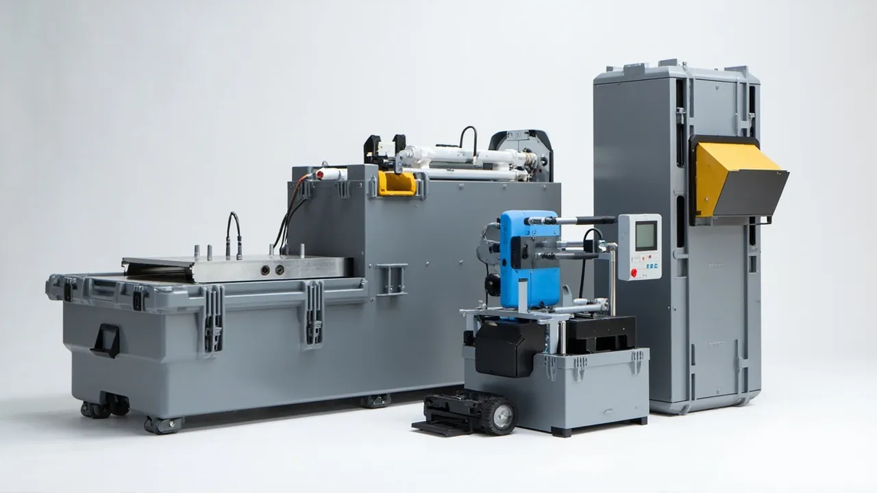
On municipal solid waste sorting lines and recycling lines, the difficulty in spare parts packaging comes not from component weight but from the cleanliness gap between two categories of parts. A screen can be a little dirty and still work. An optical sorting module fails the moment it is contaminated. The core judgement here is therefore that a solid waste sorting parts case must divide cavities by cleanliness class rather than by weight class: put the optical chain — lenses, filters, light sources, detectors — into a dedicated high-cleanliness cavity, put screens and perforated plates into a lower load-bearing zone, and stop dust migration with structural partitions rather than with thicker foam. Once abrasive dust and metal chips are free to migrate inside a case, a single thin film of contamination on an optical window has already changed the calibration state.
What follows is written for sanitation equipment manufacturers, recycling line integrators, pre-treatment workshops at waste-to-energy plants, and third-party maintenance service providers. It breaks down packaging practice for optical sorting components (near-infrared and visible light modules, lenses, filters, light sources, valve arrays, blowpipes, control units) and screening components (woven wire screens, perforated plates, tensioning mechanisms, bouncing balls and screen cleaning devices), sets out how to implement three technical constraints — cleanliness, static control and vibration control — and adds test references, receiving inspection and customization workflows. Figures quoted are empirical ranges and common industry values; each project should follow its equipment drawings, optical module datasheets and transport agreement.
Table of Contents
- From Weight Classification to Cleanliness Classification
- The Cleanliness Threshold for Optical Sorting Modules
- Lenses, Filters and Light Sources: Weak Points in the Optical Chain
- Protecting High-Speed Valve Arrays and Blow Modules
- Why Calibration State Drifts in Transit
- Screens and Perforated Plates: Deformation Is the Main Enemy
- Vibration, Shock and Environmental Stress Combined
- Three Constraints: Contamination, Moisture and Static
- Liners and Cavities: Separating Clean Zones from Load Zones
- Test References and Acceptance Criteria
- Receiving Inspection, Calibration Recheck and On-Site Repacking
- Customization Workflow and Supply Models
- Frequently Asked Questions
- Conclusion and Related Reading
From Weight Classification to Cleanliness Classification
The traditional rule for equipment case design is heavy parts low, light parts high. That rule still holds for solid waste sorting equipment, but it does not address the dominant risk. The reason is that a sorting line spare parts list contains two mutually contaminating categories.
The first category is contaminating cargo. Screens, perforated plates, bouncing balls, liners and chute components removed during maintenance carry highly complex surface residues: organic acids and moisture from food waste, statically attracted dust from plastic fragments, hard abrasive particles from metal chips and glass shards, and salt crystals left behind when leachate dries. Even after cleaning, contaminants may survive in crevices and at the roots of screen apertures.
The second category is contamination-sensitive cargo. Optical sorting modules, lens assemblies, filters, halogen or LED light sources, near-infrared detectors and signal processing boards. The failure threshold here is extremely low: an oil film, dust layer or fingerprint on an optical window reduces transmittance and introduces scatter, degrading recognition rates, while conductive dust on a board can cause leakage or short circuits.
Putting both categories into one cavity has an irreversible, one-directional consequence: a single vibration cycle is enough to migrate abrasive dust onto an optical surface, and the site usually has no way to perform a compliant clean and recheck afterwards. Cavity allocation should therefore follow cleanliness class — high-cleanliness, general-cleanliness and contaminated — enforced by structural partitioning (solid dividers, independent inner bags, independent sealing) rather than by foam alone. This follows established cleanroom equipment practice, described in cleanliness control in cleanroom equipment component cases.
The Cleanliness Threshold for Optical Sorting Modules
Optical sorting is a four-step loop: illuminate, capture, decide, eject. Degradation of signal quality at any step shows up directly in sorting efficiency and false-rejection rate. Transport protection has to follow that loop.
The optical path is the first threshold. Light from the source passes through a window onto the material surface; reflected or transmitted light returns through the window to the detector. The window is the only exposed surface in the optical path and the most easily contaminated. Window materials are usually fused silica or high-transmission glass with a coating, and the coating is sensitive to both mechanical wiping and chemical cleaning.
Detectors and filters are the second threshold. Near-infrared detectors (indium gallium arsenide, germanium or silicon devices) and filter stacks are normally enclosed inside a module housing, so the main transport risks are internal optical element displacement caused by severe shock, and coating mildew from long-term moisture ingress.
Light sources and their power supplies are the third threshold. High-power sources must not be compressed in transit, especially lamp bodies and reflectors with heat dissipation structures; reflector inner surfaces are mirrored, and a single scratch changes the light distribution.
Calibration parameters are an invisible asset. Modern optical sorters complete white balance, spectral calibration and threshold setting before dispatch, with parameters stored in the control unit. If transport shock shifts the relative position of optical elements, the parameters no longer match the actual optical path, presenting as equipment that powers up normally but sorts with reduced accuracy. Modules must therefore be rigidly located; flexible cushioning alone must never provide positioning.
| Cleanliness class | Applicable components | Permitted packaging environment | Key controls |
|---|---|---|---|
| --- | --- | --- | --- |
| High cleanliness (clean cavity) | Optical modules, lenses, filters, light source assemblies | Independent sealed inner bag plus clean liner | Dust, oil mist, fingerprints, moisture |
| General cleanliness | Control boards, sensors, harnesses, air valves | Independent compartments plus antistatic bags | Static, humidity, compression |
| Heavy duty, ordinary | Screens, perforated plates, tensioning mechanisms, bouncing balls | Lower load zone plus solid partitions | Deformation, impact, dust migration |
Lenses, Filters and Light Sources: Weak Points in the Optical Chain
Taken apart, the optical chain is not uniform in fragility, and a generic "add another layer of foam" approach solves nothing.
Lens assemblies are fragile in three places: the lens surface (coatings scratch easily), the barrel thread (impact degrades assembly coaxiality), and the focus mechanism (shock shifts the focal point). Packaging should keep lens surfaces facing inward or covered with a soft cap, give the lens its own cavity with axial restraint, and never co-pack it with other items.
Filters are thin optical plates with fragile edges, sensitive coatings and moisture sensitivity. Empirical practice is to leave the original packaging intact, place the whole pack inside a clean inner bag, and add desiccant. If unpacking is unavoidable, use a dedicated plate rack rather than stacking.
Light source assemblies (halogen lamps, xenon lamps or high-power LED modules) concentrate weight and are structurally fragile around their heat sinks. Compressed heat sink fins deform and degrade cooling, which in turn affects lamp life and spectral stability. Packaging should transfer load through the mounting flange or base; the fin zone must never bear load.
Optical windows are often removable items on the machine and may ship separately. Treat them with double-sided protection in a dedicated rigid box: one face covered with soft lint-free material, the other supported by the rigid box body, with no friction possible in between.
Clean liner material selection matters. Ordinary open-cell foam sheds particles, recycled foam may release plasticizers and halides, and paper-based materials absorb moisture and shed fibres. Choose low-outgassing, non-shedding closed-cell foam or cleanroom-grade EVA, and write material composition limits and cleanliness requirements into the technical agreement.
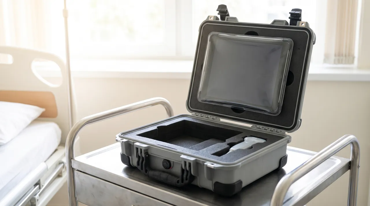
Protecting High-Speed Valve Arrays and Blow Modules
The valve array is the actuator of an optical sorter, converting a decision into a blast lasting a few tens of milliseconds. Packaging risk for these parts concentrates on two dimensions: precision and contamination.
Valve array precision shows up in response time and consistency. An array typically integrates dozens of high-speed solenoid valves on a manifold, with pilot orifices and throttle passages of very small diameter. Manifold sealing faces, air passages and mounting faces are all precision areas. Transport risks are manifold deformation exceeding flatness tolerance, dust entering air ports and causing sluggish action, and coil parameter drift from compression. The requirement is rigid location of the full row; unit-by-unit loose packing is not acceptable. If valves must be separated, plug each air port.
Blowpipes and nozzles combine a long component with precision holes. Nozzle diameter governs the spatial distribution of blast force, and deformed orifices cause misdirected blasts, visible as material wrongly ejected into the wrong chute. The answer is full-length support along the pipe, protective sleeves over nozzle zones, and axial restraint at both ends.
Air tubing and fittings are easily damaged small parts. Seals inside fittings can take a permanent set under compression, so store them in dedicated small cavities.
Air preparation units (filters, regulators, lubricators) contain diaphragms and springs and require precision-valve-grade packaging, with dust and moisture exclusion as the priority.
One further risk deserves mention: co-packing valve arrays with screens. In vibration, screens generate fine metal chips and residual dust. If they share a cavity with a manifold, dust enters the air ports. This cross-contamination is hard to diagnose on site because the symptom is intermittent missed blasts rather than total failure, and it is easily misattributed to electrical control problems.
Why Calibration State Drifts in Transit
Commissioning an optical sorter on site is expensive, and the transport chain is where that work most easily comes undone. Drift has three typical causes, and understanding them is what makes targeted packaging possible.
The first is mechanical displacement drift. The relative position between the optical module and the material channel is set by installation datums. A shock in transit can shift internal optical elements even when the housing shows no visible damage, offsetting the field of view. This is the most insidious form, because the machine powers up, produces images, and only misaligns the recognition boundary.
The second is contamination drift. Contamination on a window or lens changes light throughput and scatter distribution, shifting the characteristic signal of the same material. Contamination drift is gradual: as contamination accumulates, recognition rate declines slowly, and operators usually suspect the algorithm before the optical surface.
The third is moisture drift. Optical parts that take up moisture may develop mildew spots or haze on coatings, and detector dark current may rise. This is especially common in humid regions and on long ocean voyages.
The packaging logic that suppresses all three is unified: rigid location, clean enclosure, humidity control.
- Rigid location: the module mounting face is constrained directly by a rigid cradle inside the case; elastic elements only damp vibration and never provide positioning.
- Clean enclosure: the module goes into a clean inner bag containing desiccant and a humidity indicator card, with the case providing mechanical protection outside the bag.
- Humidity control: desiccant quantity is calculated from the net volume of the clean bag and the storage period, not estimated from the whole case volume.
For projects requiring rapid return to service, include a post-transport check list inside the case, itemizing what must be rechecked — window appearance, lens locking state, light source output, and a sorting validation run with a standard sample. This converts a vague concept of drift into executable inspection actions.
Screens and Perforated Plates: Deformation Is the Main Enemy
Screening components present almost the opposite problem to optical parts: they do not mind dirt, they mind shape change.
Woven wire screens are made from interwoven metal wire and are somewhat flexible. Their problem is not rupture but aperture distortion. After rolling or folding, sustained compression flattens or elongates local apertures, shifting the cut point; where screening accuracy matters, that shift produces out-of-spec product. Deliver screens in a large-diameter rolled form with a core support and end face guards, and never stack heavy items on the roll.
Perforated plates are rigid but thin and highly open, so their bending stiffness is lower than a solid plate of the same size. The main transport risks are mid-span bending and burr deformation at hole edges. Use face-contact cradling plus an intermediate support point, and never leave the span unsupported in the middle.
Screen tensioning mechanisms (tension hooks, pull plates, clamp bars, bolt sets) are collections of small parts easily tossed into a bag, where they suffer impact and mix-ups. Pack them as complete assemblies with a bill of materials in the case so nothing is missing on site.
Bouncing balls and screen cleaning devices are rubber or polyurethane parts whose enemies are permanent compression set and oil contamination. Bag them separately and never leave them under sustained load.
Chute liners and wear plates are heavy and belong to the contaminating category. Place them in the lower load zone behind solid partitions.
| Screening component | Main risk | Recommended delivery form | Packaging priority |
|---|---|---|---|
| --- | --- | --- | --- |
| Woven wire screen | Aperture distortion, edge fraying | Large-diameter roll | Core support, end face guards, no stacking load |
| Perforated plate | Mid-span bending, hole edge deformation | Flat or on edge | Face-contact cradle, intermediate support |
| Tensioning mechanism | Impact, mixed-up or lost parts | Packed as an assembly | Compartments per assembly, list in case |
| Bouncing balls | Permanent set, oil contamination | Bagged individually | No load, keep away from oil and sunlight |
| Chute liner | Impact, dust migration | Lower load zone | Solid partition, edge guards |
| Screen cleaning device | Jamming, deformation | Dedicated small cavity | Restraint, dust exclusion |
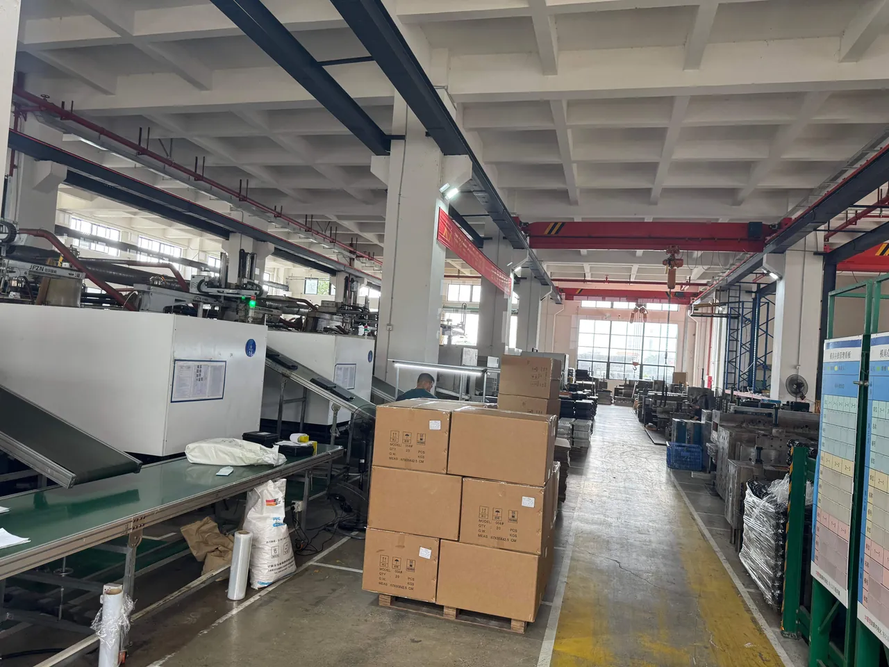
Vibration, Shock and Environmental Stress Combined
Transport conditions for solid waste sorting spares are usually more demanding than for general industrial spares, because projects cluster at municipal sanitation facilities and recycling parks, the last-mile road surface is often poor, and manual handling accounts for a high share of loading and unloading.
Vibration is a sustained load. Its effect on optical parts is cumulative loosening, on screens it is contact surface wear, and on valve arrays it is fastener loosening. The key to vibration protection is not wrapping components more thickly but eliminating any relative motion between component and case.
Shock is a transient load, mainly from handling drops and hard braking. Protection means spreading the peak force: route it into the frame through cradles, and extend the impulse duration with elastic pads, thereby lowering the peak acceleration the component sees.
Environmental stress includes temperature, humidity, rain and salt fog. Here the requirements on the case itself exceed those on the components: after rain and sunlight, the case must not lose stiffness through moisture absorption, nor become brittle through UV ageing.
The combined effect of the three deserves emphasis. Moisture softens paper-based and timber support elements, which then lose positional accuracy, so components displace further under vibration and shock; that displacement causes friction and new contact, closing a vicious circle. Internal support structures should therefore use low-moisture-absorption materials, and timber elements should be moisture-treated and backed by barrier layers where required.
Three Constraints: Contamination, Moisture and Static
Packaging for sorting line spares must satisfy three constraints simultaneously, and they sometimes conflict, so trade-offs belong in the design phase.
The contamination constraint demands reduced particle migration: non-shedding liners, independent sealing for contaminated parts, independent inner bags for clean parts, packing performed in a relatively clean area, and avoidance of low-density foam that cracks and crumbles.
The moisture constraint demands controlled internal humidity: barrier liners, metered desiccant, humidity indicator cards, and sensible elevation during storage. For optical parts, preventing coating mildew is mandatory; for rubber parts, excessively low humidity can accelerate ageing, so humidity targets can differ between cavities in the same case.
The static constraint works in two directions: protecting boards and sensors from electrostatic damage, and preventing discharge when handling spares associated with combustible dust. Measures include antistatic bags and liners, operator grounding, and appropriate case markings. Board-level practice follows ESD shield case structure and grounding requirements.
| Constraint | Primary targets | Means | Conflict with other constraints |
|---|---|---|---|
| --- | --- | --- | --- |
| Contamination | Optical windows, lenses, boards | Independent inner bags, clean liners, zoning | Conflicts with minimizing packaging layers |
| Moisture | Optical parts, rubber parts, metal parts | Barrier film, desiccant, indicator cards | Rubber parts dislike excessive dryness |
| Static | Boards, sensors, combustible-dust-associated parts | Antistatic materials, grounding, markings | Antistatic materials may reduce barrier performance |
| Vibration | Optical paths, manifolds, plates | Rigid location plus elastic damping | Conflicts with fast on-site access |
The trade-off principle can be stated simply: cleanliness outranks vibration control, and vibration control outranks convenience. When cleanliness conflicts with convenience, keep cleanliness; when vibration control conflicts with convenience, keep vibration control. Convenience problems can be solved through procedures and spare parts management; cleanliness and positioning failures cannot be recovered on site.
Liners and Cavities: Separating Clean Zones from Load Zones
The liner is where this classification logic becomes physical. Design around three zones and one separation.
The clean zone sits on the upper layer or in a dedicated small chamber, lined with cleanroom-grade closed-cell material. Every optical part goes into a clean inner bag with desiccant, and the cavity has a top cover so that only the current item is exposed during handling.
The actuator zone occupies the middle layer for valve arrays, blowpipes and control components. Manifold-type parts are rigidly located, board-type parts are antistatic packed, and long pipe sections are fully supported.
The load zone occupies the lower layer for screen rolls, plates and liners. This zone carries most of the stacking load, so cradle strength and case floor structure are the design focus.
Solid separation between zones is essential. Use rigid dividers — engineering plastic panels, or metal plates with a non-metallic coating — rather than relying on foam layers alone; the divider's job is to block the migration path for dust and debris. For heavily contaminated maintenance parts, seal them in an independent inner bag before placing them in the load zone, creating second-level isolation.
Access sequence design matters too. On site, screens are usually replaced first and optical modules inspected afterwards, so layout should place high-frequency items toward the outside and low-frequency items deeper in, avoiding repeated opening of the clean cavity to retrieve a single bouncing ball and exposing it to contamination.
Test References and Acceptance Criteria
Verification for sorting equipment cases should cover mechanical and environmental lines, with a separate check for cleanliness.
Mechanical references: stacking, vibration, impact and drop methods from the GB/T 4857 series, combined according to the actual transport mode; ISTA programs for intermodal shipments; ASTM D4169 to sequence tests around a distribution cycle for export projects.
Environmental references: humidity and thermal cycling tests to assess condensation and mildew risk; salt spray methods to assess corrosion protection on metal parts and fasteners. Where a contract names MIL-STD-810H, position it as a source of environmental test methods rather than a product qualification, note that citing the method does not constitute a military certification, and list the method numbers and severity levels used. For the boundaries of such citations, see compliant use of MIL-STD-810H environmental testing.
Cleanliness checks: general standards rarely cover these, so define them in the technical agreement. Suggested checks include visual inspection of the clean cavity for visible particles after opening, wiping the outer packaging surface of optical parts with a white cloth to reveal residue, reading the humidity indicator inside the inner bag per the agreed method, and confirming the appearance and coating condition of critical optical parts.
Acceptance criteria in three groups:
- Positioning: module mounting faces seat on cradles with no discernible gap, and no displacement marks appear after transport testing.
- Cleanliness: no visible particle deposits in the clean cavity, and optical part packaging intact with no breaches.
- Mechanical: screen rolls not flattened, plate flatness within agreed tolerance, manifold faces undeformed.
For a broader comparison of liner materials, see performance comparison of case liner materials.
Receiving Inspection, Calibration Recheck and On-Site Repacking
For sorting equipment, receiving inspection is not only about whether anything broke but about whether the parts can be used directly.
| Inspection item | Method | Pass criterion | Action on failure |
|---|---|---|---|
| --- | --- | --- | --- |
| Case and seals | Visual | Seals intact, no rain ingress marks | Record and inspect clean cavity first |
| Clean cavity humidity | Read indicator card | Below colour-change threshold | Recheck optical part appearance |
| Optical windows | Visual with side torch | No scratches, haze or deposits | Do not wipe; contact manufacturer |
| Lens locking | Manual check | No looseness, focus ring unmoved | Relock per manual and recalibrate |
| Filters | Visual | No mildew, no coating lift | Replace |
| Light source assembly | Visual and power-up | Fins undeformed, output normal | Assess replacement |
| Valve array | Visual and air test | Air ports clean, consistent actuation | Clean and retest |
| Screen roll | Visual and unroll sampling | No flattening, apertures not visibly distorted | Assess concession by area |
| Plate flatness | Surface plate and feeler gauge | Within agreed tolerance | Straighten or replace |
| Accompanying documents | Cross-check | List matches, calibration backup complete | Complete before warehousing |
The calibration recheck principle deserves separate mention. If the optical module packaging is intact, humidity indicators are normal, and no displacement marks appear on opening, the module can usually go straight into service. But if the case shows clear drop marks or the clean cavity seal is breached, run a sorting validation with a standard sample even when nothing looks wrong, replacing subjective judgement with an actual result.
For on-site repacking, keep the original liner and clean inner bags rather than discarding them. Sorting line spares turn over quickly, and the same case is often reused within months; once the liner is lost, components can only be packed bare, sharply raising subsequent risk.
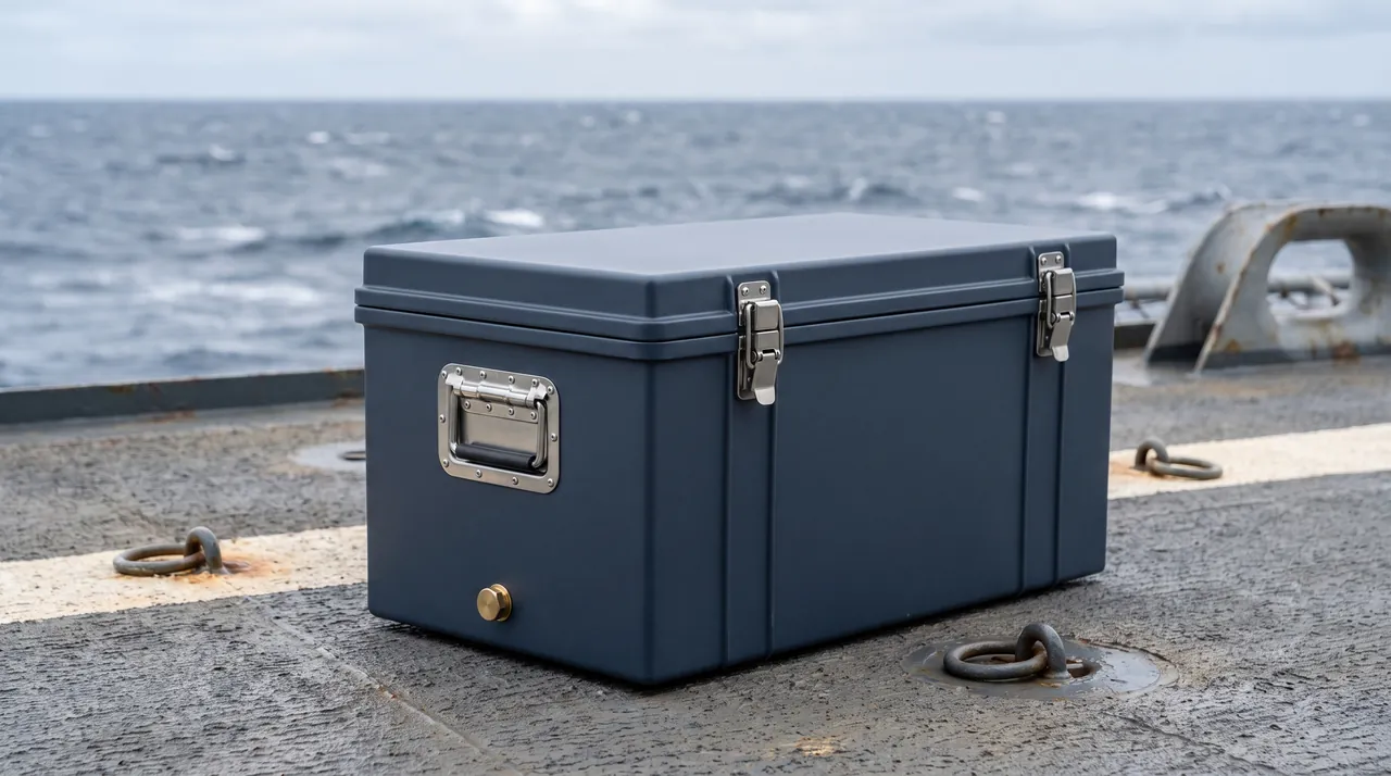
Customization Workflow and Supply Models
Spare parts lists differ widely between sorting projects. Even for a single integrator, optical module models, screen widths and manifold lengths vary by project, so case types need to be project-specific rather than selected from a standard catalogue. A five-stage workflow is recommended.
Stage one, structure the list. Split spares into three tables — optical and electronic items, actuation and pneumatic items, mechanical and consumable items — each annotated with cleanliness requirements, dimensions, weights and quantities.
Stage two, plan the cavities. Determine the number of zones, internal dimensions, liner materials and material compatibility, and specify which items need independent inner bags and which need antistatic packaging.
Stage three, sample case and physical fit validation. Build a sample case, load it with the real list, and check access convenience and component restraint.
Stage four, testing and small-batch production. After the agreed tests pass, move to volume production, retaining production records against the project number.
Stage five, on-site delivery support. Provide layout drawings, repacking instructions and storage guidance, and support on-site acceptance where required.
On the manufacturing side, Kexin New Materials (Guangdong) Co., Ltd. produces this case family. Case exterior dimensions and liner layouts can be customized around the sorter's optical module arrangement and screen widths. In addition to its own brand supply, the company accepts OEM/ODM contract manufacturing commissions and distributes to global markets through wholesale and regional agency channels, with test documents and material certificates available under the terms of the contract. Where a project also covers dust collection or dewatering equipment components, review the approach in dust collector equipment cases so the case family can be planned as one series, reducing production changeovers and on-site management cost.
Frequently Asked Questions
Q: Why must an optical sorting module never share a cavity with a screen?
A: Because the contamination relationship is one-directional and irreversible. Whether a screen is new or removed during maintenance, dust is trapped at the roots of apertures and between the woven wires, including plastic fragments, glass shards and metal particles that are hard abrasives. Transport vibration keeps these particles suspended and migrating inside the case, and once they adhere to an optical window or lens coating they reduce transmittance and introduce scatter, directly changing the recognition signal. The site generally lacks the conditions for a compliant clean: wiping with an ordinary cloth scratches the coating, and solvents may attack the coating or the sealant, so the result is often worse than leaving it alone. In the other direction, an optical module never contaminates a screen, which is what makes this a one-way risk. In engineering practice, separate the cavities, block the migration path with a rigid divider, and add a clean inner bag around the optical items for second-level isolation. If co-packing is unavoidable, the clean cavity must be fully sealed and must not share a desiccant charge with the rest of the case.
Q: What are lenses and filters most vulnerable to in transport?
A: Three things, in a fixed order: scratching, moisture and loosening. Scratching comes from friction and improper wiping; lens and filter coatings are only microns thick, so any hard contact leaves a permanent mark. Such damage may not show up in outgoing inspection and often surfaces only after some operating time, when throughput has fallen. Moisture comes from high humidity and thermal cycling; coatings that absorb moisture may develop mildew or haze, and detector dark current may rise, a problem particularly pronounced in humid seasons and on long sea voyages. Loosening comes from shock and vibration; once barrel threads or focus mechanisms shift, the optical focal point no longer matches the factory calibration, presenting as a machine that powers up but sorts less accurately. Countermeasures follow directly: soft caps on lenses in dedicated cavities, filters kept in original packaging inside clean inner bags, rigid cavity location with desiccant and humidity indicator cards, and a strict rule against opening bags to inspect in a non-clean environment.
Q: How should screens removed during maintenance be prepared for packing?
A: Three steps, and the order cannot be reversed. First, remove residues: screens pulled during maintenance often carry organic residue, salt crystals from dried leachate and fine metal chips, which should be removed by an appropriate method while avoiding cleaning agents that introduce new contaminants; parts with heavy organic residue should be thoroughly dried afterwards, or they become a persistent moisture source inside the case. Second, assess the component: aperture distortion, edge fraying and worn tension edges are unrepairable damage and should be recorded honestly and marked on the packing list, so that they cannot be mistaken for serviceable spares on site. Third, form and isolate: deliver rolled or laid flat, with rolls needing core supports and end face guards and flat-packed screens needing face-contact cradles without unsupported mid-span. Because these parts belong to the contaminating category, seal them in an independent inner bag before placing them in the load zone, and never share a cavity with optical or pneumatic items, to prevent dust migration.
Q: Can intermittent missed blasts in a valve array be traced back to transport?
A: A meaningful share of on-site intermittent missed blasts is related to transport contamination rather than electrical faults. Pilot passages and throttle orifices in high-speed solenoid valves are typically only fractions of a millimetre across, and once airborne dust in the case enters an air port under transport vibration, it accumulates in the passage. After commissioning the symptom is sluggish or intermittent action, and it is inherently intermittent: pressure fluctuations may temporarily clear a passage, only for it to clog again. This is easily misdiagnosed as a control or coil problem, and troubleshooting is expensive. Transport-side prevention means fitting air port plugs on individual valves or entire rows, rigidly locating manifolds to prevent deformation, keeping the packing area free of airborne dust, and introducing no debris-shedding materials into the case. On-site practice means removing plugs and performing an air check first, verifying response valve by valve per the manufacturer's instructions, rather than waiting until full line commissioning to chase faults one at a time.
Q: How should the roll diameter for a woven wire screen be determined?
A: Three factors jointly determine it, and there is no universal number. The first is wire diameter and weave structure: larger wire and denser weave demand a larger minimum bend radius, and an excessively tight roll distorts apertures and causes local yielding. The second is screen length and width: long screens must be rolled, and the core diameter must be large enough to prevent crushing of inner layers; wider screens also need even tension on both sides during rolling to avoid a conical roll. The third is storage and transport duration: short turnovers tolerate a smaller roll diameter, while long storage or repeated transfers call for a larger diameter with core support, because a roll under sustained load creeps over time. Empirical practice is to determine the smallest diameter at which no aperture distortion occurs, then add one step as a safety margin. Fit end face guards at both ends of the roll and never stack anything heavy on top of it.
Q: Does the clean cavity in the case need humidity control?
A: Yes, and the requirement is usually stricter than for ordinary cavities. There are two reasons. First, optical parts are moisture-sensitive: coatings in a humid environment may develop mildew or haze and detector dark current may rise, which is invisible in the short term but affects long-term stability. Second, the clean cavity is an independent sealed volume with little air exchange, so once moisture enters it cannot readily escape, and the cumulative effect is more pronounced than in a large space. In practice, fit metered desiccant inside the clean inner bag and include a humidity indicator card, calculating desiccant quantity from the net volume of the bag and the storage period rather than from the whole case volume. Fit a window so the indicator can be read without opening the case. Note that desiccant should be kept away from optical parts and reliably secured, so it cannot shift in transit and touch a lens or window. For spares stored longer than six months, check the indicator periodically and replenish desiccant as needed.
Q: Which tests should a solid waste sorting parts case undergo?
A: Work along three groups. The first is mechanical testing: select stacking, vibration, impact and drop methods from the GB/T 4857 series according to the actual transport mode, or use ISTA programs or ASTM D4169 sequenced around a distribution cycle, to verify that cradles, dividers and restraints can carry transport loads while holding components in position. The second is environmental testing: humidity and thermal cycling tests to assess condensation and mildew risk, and salt spray methods to assess corrosion protection on metal parts and fasteners. Where a contract cites MIL-STD-810H, use it as a reference to environmental test methods and state clearly that this is a reference to test methods, not a military certification, together with method numbers and severity levels. The third is cleanliness and functional confirmation, which must be defined by the project itself: particle inspection of the clean cavity, reading humidity indicators inside inner bags, confirming optical part appearance and coating condition, and where warranted a sorting validation with a standard sample, replacing subjective judgement with an actual sorting result.
Q: How should the on-site spare parts store hold these cases?
A: Work to four rules: elevate, exclude light, control temperature, and recheck periodically. Elevation means raising the case base off the floor, avoiding condensation driven by ground cooling and preventing water at floor level from soaking the case; this matters most in humid seasons and in winter when floor temperature is low. Light exclusion means avoiding prolonged direct sunlight, which embrittles case materials through UV ageing, hardens seals and accelerates rubber part ageing. Temperature control means storage in a space with modest temperature swings; an open yard with wide day-night swings is the harshest environment for thermal cycling and the most likely to trigger condensation. Periodic rechecking means tiered management by storage duration: keep original packaging within three months; check humidity indicators and replenish desiccant from three to six months; open and re-inspect optical part appearance and screen form beyond six months, reapplying barrier and rust prevention if necessary. Keep cases away from walls, provide a rain-shedding top layer, and never exceed the marked stacking tiers.
Conclusion and Related Reading
The design logic for solid waste sorting equipment cases comes down to one sequence of priorities: cleanliness class determines cavity allocation, cavity allocation determines structure, structure determines materials, and materials determine foam thickness last of all. Isolate contaminating cargo such as screens in the lower layer and seal it independently; place the optical chain in a rigidly located, humidity-controlled clean cavity; give pneumatic actuators dust and static protection; and let the case itself provide mechanical protection, light exclusion and rain shedding. Once these four things are in place, the receiving inspection targets become unambiguous: optical windows free of haze and scratches, clean cavity humidity indicators normal, manifold air ports free of dust, and screen apertures free of visible distortion.
Related Reading