

A 200 mm Schmidt-Cassegrain showed elongated stars on its first night after a journey, and inspection found that the three collimation screws on the secondary mirror had crept loose during two hundred kilometres of mountain road. The tube had no visible damage and the case was intact. The only loss was the invisible part: optical alignment. A telescope case is judged differently from an ordinary equipment case. The criterion is not whether the shell cracked but whether the optical surfaces were scratched, whether the coatings were contaminated, and whether the optics can still be collimated in a single pass.
JUNZHIJIA's protection principle is that a telescope case exists first to keep the optical path valid on arrival, not merely to survive a drop. Every internal design decision, from support position and contact pressure to compartment separation and humidity control, serves two outcomes: zero contact damage to optical surfaces and zero relative movement within the optical assembly. The sections below cover optical weak points, collimation retention, foam selection, compartment layout, field conditions and an acceptance checklist.
Table of Contents
- Cost of Failure and Protection Targets for Telescope Cases
- Optical Weak Points: Primary, Secondary and Corrector
- Collimation Retention Under Transport Vibration
- Foam Selection for Optics: No Shedding, No Plasticiser, Controlled Pressure
- Supporting the Tube: Ring Cradles and Compliant Travel Limits
- Stowing the Mount Head, Counterweights and Accessories
- Electronic Accessories: Dew Heaters, Controllers and Cables
- Field Observatory Conditions: Dust, Dew and Night Temperature Drop
- Thermal Equilibrium and Transport Limits for Large Mirrors
- Case Structure, Stacking and Pressure Equalisation
- Transit Options Compared: Soft Bag, Foam Case and Cradled Case
- Packing and Acceptance Checklist
- Frequently Asked Questions FAQ
- Conclusion and Related Reading
Cost of Failure and Protection Targets for Telescope Cases
Failure modes in telescope transport differ from industrial equipment. Industrial equipment suffers most when a broken case lets contents collide. Telescopes suffer most from damage that is not visible at first. A tube that looks perfect may have lost sharpness permanently at high magnification because a grain of abrasive was ground into the mirror coating, or may develop haze after months because the foam liner released plasticiser vapour onto the coatings, or may need recalibration after every trip because the mirror cell screws migrated.
The protection targets can be reduced to four. Zero contact with optical surfaces means no material ever touches the mirror, corrector or lens group, and nothing capable of falling is left above them. Zero relative displacement means the primary mirror, secondary mirror, mirror cell, focuser and tube do not move permanently under any transport excitation, and in particular that collimation state is preserved. Chemical cleanliness means no outgassing material exists inside the cavity, because aluminised surfaces and metal tubes are especially vulnerable to sulphides and organic acids. Environmental stability means relative humidity stays in a range where mould cannot establish, and temperature change is slow enough that condensation cannot form on optical surfaces.
The basis for these targets combines two families of practice. Transport environment follows the ISTA series and ASTM D4169, with structural criteria referencing MIL-STD-810H Method 514 for vibration and Method 516 for shock. Optical surface cleanliness comes from optical industry practice rather than a single standard. Aligning all three in one drawing set is what distinguishes a telescope case from a generic instrument case.
Optical Weak Points: Primary, Secondary and Corrector
Weak points differ completely between optical designs, so protection must start from the light path rather than the case outline.
Schmidt-Cassegrain and Maksutov-Cassegrain designs carry a thin corrector plate at the front of the tube. Its thickness is often only ten to twenty millimetres while its diameter can exceed two hundred, making it extremely sensitive to point loading and edge compression. Worse, its surface carries an anti-reflective coating that is softer than the substrate, so any textile fibre rubbed across it leaves a mark that is difficult to remove. The rule is that the corrector must never carry axial load; support must land on the metal tube ring instead.
Newtonian reflectors place the primary mirror at the bottom, carried on a cell with three or nine flotation points. If the tube is packed vertically and subjected to downward acceleration, the mirror presses into its supports. If it is packed horizontally, the mirror can slide axially. Many cells include transport locking screws, which must be tightened before packing with a reminder label inside the case. This is the single most frequently omitted and most effective step.
Refracting objectives consist of two or more elements, either cemented or air-spaced. A cemented group develops stress at low temperature because the cement and the glass have different expansion coefficients. Winter transport should avoid leaving the case in a cold vehicle for extended periods, and the case should not be opened immediately on entering a warm room, so the lens group can return to ambient slowly.
The secondary mirror is the shared weak point of every reflector. It hangs in the light path on one or four vanes, and is usually fixed by three adjustment screws plus a central screw. Adjustment screws rotate slowly under sustained vibration, which is the primary cause of collimation loss. Workable countermeasures include screws with nylon inserts, recording the baseline position before packing, and fitting a removable transport stop behind the secondary so the mirror is pressed against a defined position instead of being held only by screw friction.
The focuser and eyepiece interface is another stress concentration. An extended drawtube forms a cantilever, and vibration fatigues the joint. Retract the drawtube to its shortest position and lock it before packing, together with any focus lock screw.
Collimation Retention Under Transport Vibration
Collimation loss rarely comes from a single impact. It comes from long, low-amplitude repeated excitation. Micro-movement of screws under vibration makes them creep along the thread, and the smaller the amplitude and the closer the frequency to the screw's natural frequency, the faster the creep. This explains why a long road journey damages alignment more reliably than a short carry.
Three families of countermeasure suppress screw creep. The first increases thread friction using nylon insert nuts, thread-locking compound, or spring washers. The second removes clearance by applying a slight preload after adjustment so the thread flanks stay in contact on one side. The third provides external travel limits, fitting an independent transport stop beside the secondary or the mirror cell so the stop carries the load in transit and the adjustment screws carry none.
Case design must also avoid resonant amplification. A telescope tube is a slender cylinder whose first bending mode usually falls between a few tens of hertz and slightly over one hundred hertz, while road transport excitation concentrates between a few hertz and a few tens of hertz. If the case and support system have a natural frequency inside the overlap, vibration is amplified several times. The remedy is to shift the support frequency either up or down depending on the tube's own natural frequency, and this must be established by test rather than assumed. Test methods and acceptance criteria are discussed in Transport Vibration Testing.
Recording a baseline before packing is the key tool for verifying collimation retention. Collimate with a Cheshire eyepiece or laser collimator, record the screw positions by marking or photographing them, and repeat the same measurement on arrival. If the deviation exceeds the tolerance implied by the instrument's resolution, the case design needs improvement rather than a simple recalibration.
Foam Selection for Optics: No Shedding, No Plasticiser, Controlled Pressure
Foam is the most error-prone element of a telescope case because it performs three duties at once, cushioning, locating and isolating, and these duties do not all favour the same material.
The first requirement is no shedding. Open-cell foam, and any foam with loose cut debris, releases particles continuously under vibration, and once a particle lands on an optical surface it will be pressed into the coating during the next cleaning. Closed-cell crosslinked polyethylene foam, polyethylene board and moulded EVA liners are all acceptable, while ordinary open-cell polyurethane sponge should be excluded. The test is simple: rub the surface repeatedly by hand and watch for loose particles.
The second requirement is no plasticiser. Flexible PVC foam contains large amounts of plasticiser that migrates slowly inside a sealed case and deposits a haze on optical surfaces and metal tubes. Confirm the base polymer and additive list, and avoid chlorinated polymers and sulphur-bearing rubbers.
The third requirement is controlled contact pressure, and this is the most commonly misunderstood. Softer is not safer. Foam that is too soft lets the tube move inside the case and transfers load to the focuser and the secondary support vanes, which are the weakest structures. Foam that is too hard concentrates stress at the contact points, which is bad for thin tube walls and coated surfaces alike. The correct approach distributes the tube weight over sufficient contact area so the pressure per unit area stays low and even.
Contact pressure can be quantified with a single trial. Place pressure-indicating paper or a thin film sensor between the tube and the foam, close the case and read the imprint. A localised dark mark means excessive pressure at that point; a uniformly faint or absent imprint with a tube that can be pushed by hand means insufficient restraint. One such trial fixes the foam density and contact area for that tube model permanently. For the wider trade-offs between liner constructions, see Cushion Liner Structures.
A fourth requirement is durability, because foam takes a permanent set after repeated compression. Material with a high compression set collapses after several journeys and loses its restraint, and crosslinked polyethylene generally outperforms ordinary polyurethane over a long service life.
Supporting the Tube: Ring Cradles and Compliant Travel Limits
A telescope tube is a slender cylinder with a high length-to-diameter ratio, and its centre of gravity is rarely at the geometric centre. Support design that ignores these two facts produces the classic error of a tube suspended at both ends and loaded in the middle.
Ring cradles are the most dependable arrangement. They place complete circular saddles at two or more cross-sections so radial load is distributed evenly and the tube cannot bend from one-sided loading. The inner diameter should be slightly larger than the tube, lined with a low-hardness, non-shedding pad, so the tube is enclosed in a small clearance rather than clamped. Spacing between saddles should follow tube length and stiffness: too far apart and the middle section can flex under vibration, too close and the assembly cannot resist pitching rotation.
Compliant travel limits control the axial and rotational degrees of freedom. Fit flexible stops at both ends of the tube to limit axial sliding and rotation about the axis, but make the stops themselves recoverable so they do not transmit shock directly into the tube ends. Stops should land on the metal tube body and avoid the front face where the corrector sits and the rear face where the focuser is mounted.
The dovetail plate or mounting rings are natural high-stiffness regions and should be the primary load path. Letting the tube weight transfer mainly through the mounting plate, with ring saddles providing secondary support and radial location, gives the best combination of stiffness and safety.
Three practices should be avoided. Clamping the tube between two flat boards creates line contact and pressure concentration. Strapping the tube to a baseboard with webbing allows the strap to relax under vibration. Seating the tube on the baseboard without upper restraint allows bouncing that produces axial impact. None of these shows a problem on a short trip, and all three produce dependable damage over long or intermodal journeys.
Stowing the Mount Head, Counterweights and Accessories
The mount and counterweights are the heaviest items in the case and therefore its greatest internal hazard. A counterweight is typically a solid metal disc of five to eleven kilograms, and a single sudden deceleration is enough to drive it through a divider and into the tube if it can move.
The correct arrangement isolates the counterweights in one corner of the case, fixed by a dedicated saddle or cavity, positioned below or remote from the tube cavity. If the case has wheels, the counterweight cavity should sit near the axle so the overall centre of gravity stays low. Counterweights should be located by shape-matched contact plus a mechanical stop rather than foam alone, because foam relaxes after a few dozen handling cycles.
An equatorial mount head has two movable axes. Lock both before packing where locking levers are provided, and rotate the right ascension axis to the normal counterweight-down position so the centre of gravity sits near the geometric centre of the head. Heads typically weigh ten to forty kilograms, so the case needs a pallet base with fork pockets and internal load-bearing beams that carry the weight straight into the walls. The base should be locally thickened or fitted with metal inserts so screws cannot pull out after repeated loading.
Accessories should be laid out on the principle of small, valuable and easy to lose. Eyepieces, filters, Barlow lenses, finderscopes, data cables and hand controllers each deserve a pre-cut foam cavity slightly deeper than the item, with a soft overlay so the item is lightly held when the lid closes. Eyepiece cavities need particular care because both ends are optical surfaces: the cavity should carry the eyepiece on its barrel and leave both ends unsupported.
Traceability matters as much as protection. Labelling each cavity with its contents and fixing a packing list inside the lid shortens every packing cycle and reduces the chance of leaving something behind.
Electronic Accessories: Dew Heaters, Controllers and Cables
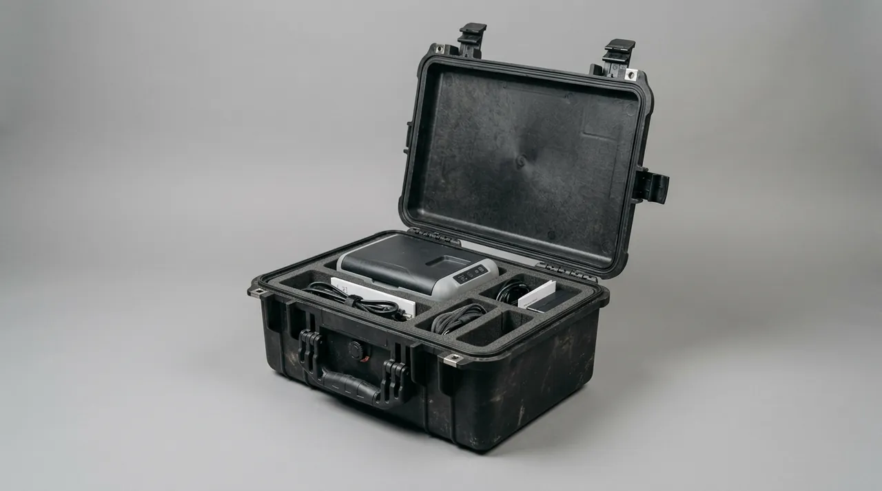
Modern observing setups depend on electronic accessories: dew heater strips, controllers, power supplies, mount controllers, guide cameras, computers and a great deal of cable. These tolerate mechanical shock less well than optics but are more sensitive to moisture.
A dew heater strip is usually a resistive element inside a fabric or silicone sleeve, and repeated tight bending breaks the internal conductor. Coil it at its natural bend radius, never crease it, and never leave a counterweight resting on it. The connector is the weakest point and should be individually wrapped and secured so the cable cannot be pulled at the joint.
Controllers and power supplies fear condensation more than rain. In the field, where the diurnal temperature range is large, moving equipment from a cold environment into a warm one can form condensation inside the housing, and powering up afterwards risks a short circuit. Fit rechargeable desiccant packs inside the case and use a hydrophobic breather element so pressure equalises while vapour and particles are blocked. If the case is fully sealed, let it stand indoors until temperature equalises before applying power.
Cables are the most overlooked hazard and can become invisible attackers. A loose cable whips around during transport and can strike optical surfaces. Group all cables in a dedicated net bag or cable cavity and protect the connectors. Coil excess length into a fixed loop rather than stuffing it into gaps.
Air transport adds a lithium battery restriction. Batteries for controllers and guide cameras are normally not permitted in checked baggage and must be carried or declared under dangerous goods rules, so a removable inner pod for batteries is a useful design feature. Where a case must cross a significant pressure differential, fitting a Pressure Equalization Valve prevents the gasket being forced open or the body bulging.
Field Observatory Conditions: Dust, Dew and Night Temperature Drop
The real service environment of a telescope case is far harsher than a laboratory: dust, dew, sudden rain, and the rapid cooling of structure after sunset.
Dust matters because of particle hardness. Fine sand often contains quartz, which is harder than most optical coatings. Once abrasive particles are inside the case and trapped between tube and foam, every journey becomes a grinding operation. Dust control depends on sealing class and cleaning discipline. The case should reach at least IP65 to IEC 60529 and GB/T 4208, with silicone or EPDM gaskets and a deep stepped rebate at the mouth. The tube exterior should be wiped before packing, and footwear and clothing cleaned before handling.
Dew forms when an optical surface falls below the dew point of the surrounding air. The most dangerous moment is not during observing but when a cold-soaked telescope is carried into a warm lodge or vehicle at the end of the session, when airborne moisture condenses on the mirror and metalwork. The correct response is not to open the case immediately. Let it stand indoors for several hours until the internal temperature approaches ambient, then open. Desiccant inside the case lowers the risk further. A relative humidity band of 30 percent to 45 percent inhibits coating fungus while avoiding the grease drying that excessive dryness causes.
The night temperature drop affects optical and mechanical fit. Aluminium tubes and steel screws have different expansion coefficients, and a 15 degree Celsius fall can change their relative dimensions by tens of microns, showing up as a stiff focuser or a small gap at a tube end face. This is harmless in normal use, but where transport crosses a large temperature range the rate of change should be limited so the tube is not gripped or released inside the case.
Sudden rain tests water resistance. IP67 means brief immersion does not admit water, but a telescope case more often faces sustained rain impact, where gasket compression set and the drainage geometry at the case mouth determine real performance. The mouth should include a drainage channel so water cannot pool on the sealing surface, and external ribs should shed water rather than forming sumps.
Thermal Equilibrium and Transport Limits for Large Mirrors
Mirrors above 300 millimetres introduce three additional problems: self-weight deflection, long thermal time constants, and the brittleness of glass at low temperature.
A large mirror sags under its own weight when placed horizontally, and deflection grows with the fourth power of diameter. If the cell has too few support points or a poor distribution, prolonged storage causes permanent deformation, so a large tube should be packed in the attitude that matches its cell support geometry rather than being tilted arbitrarily. Some cells include transport locks or transport pads, which must be engaged before packing.
Thermal inertia is both an image quality issue and a transport issue. A 400 millimetre borosilicate or glass-ceramic blank can take hours to return to room temperature after a cold night. If it is packed and moved into a very different climate immediately, the internal temperature gradient creates stress, which rarely causes fracture but lengthens the subsequent equilibration time. The workable approach is passive insulation rather than active heating, letting the blank return to ambient at its own rate.
Low-temperature brittleness is a shared weakness of all glass. Impact resistance falls at low temperature, which matters most for winter transport at high latitudes, and the relevant test methods are covered in Low Temperature Brittleness Testing. For large mirrors, avoid handling at extreme low temperature and keep handling motions slow to prevent instantaneous impact.
Altitude and air pressure also belong in the assessment. At high altitude the lower air density changes cooling rates and therefore the assumptions behind cavity humidity calculations. In air freight, falling hold pressure creates a differential across a sealed case, and without a breather element the gasket can be forced open so the case draws in external moisture on landing. These factors should be evaluated at the transport planning stage rather than discovered in service.
Case Structure, Stacking and Pressure Equalisation
A telescope case must deliver stiffness, sealing and portability simultaneously, and these three requirements frequently conflict.
Stiffness comes from wall thickness, reinforcement ribs and the geometry of the case mouth. A tube cavity is a long void, and the side walls bulge under lateral load unless controlled by external ribs or internal dividers. Dividers also separate the tube, mount and accessory cavities so the inertia of heavy items cannot transfer between compartments. Ribs should follow the primary load directions rather than being shallow decorative mouldings.
Stacking load must be calculated from the actual stacking height with dynamic amplification included. Telescope cases are rarely stacked in large numbers, but warehouses and container loading commonly place two or three high. Multiply the static stack load by a dynamic factor and check the lid and the sealing face specifically. Where stacking is expected, the lid should carry dedicated load pads so the weight of the upper case passes straight into the walls instead of onto the gasket.
Pressure equalisation has already been mentioned, but the mounting position deserves emphasis. Fit the valve high on the body, away from standing water and spray direction, and make it a replaceable component so a failed seal can be renewed without scrapping the case.
Carrying design is also structural. A loaded telescope case usually exceeds what one person should lift, so wheels and a telescopic handle should be combined, with the handle retracting inside the case outline so it cannot be knocked off in transit. Handles should sit near the centre of gravity so lifting does not tilt the case and load the tube unevenly.
Gasket durability determines service life. Silicone gaskets lose resilience under repeated compression and ultraviolet exposure, showing up as an uneven imprint on the sealing face after closing. Replace gaskets every two years or when ageing becomes visible, and re-verify airtightness afterwards.
Transit Options Compared: Soft Bag, Foam Case and Cradled Case
There is no single correct transport solution for telescopes. The choice depends on aperture, usage frequency, transport mode and budget. The table below places the three common options on the same scale.
| Criterion | Soft bag | Hard case with general foam | Hard case with custom cradle |
|---|---|---|---|
| --- | --- | --- | --- |
| Typical aperture | 60-150 mm | 150-250 mm | Above 200 mm or high-value systems |
| Collimation retention | Weak, recollimation after every trip | Moderate, depends on foam condition | Strong, secondary and cell independently limited |
| Drop resistance | Absorbs light knocks only | 0.8-1.2 m depending on foam | Above 1.2 m depending on structure |
| Optical surface protection | Depends on fabric and handling | Depends on foam thickness and contact pressure | Ring support, no direct contact |
| Counterweights and accessories | Usually cannot be stowed | Can be stowed but items press on each other | Separate cavities with mechanical stops |
| Humidity control | None | Desiccant possible, limited effect | Sealed cavity with breather element |
| Water and dust resistance | None | Depends on case, up to IP67 | Up to IP67/IP69K |
| Weight | Lightest | Heavier | Heaviest |
| Packing time per trip | Shortest | Moderate | Longest |
| Unit cost | Lowest | Moderate | Highest |
| Best suited to | Short urban trips, carry-on use | Regular self-drive observing, short transfers | Long distance, intermodal, fixed site transport |
The decision sequence should be: first, will the case face long distance or intermodal transport; second, what is the aperture and total system value; third, how often does it travel. If transport happens monthly or more and the aperture is large, the amortised cost of a custom cradle becomes the economical choice over time. For short urban carry, a soft bag plus careful handling is sufficient.
One caveat applies to the hard case with general foam, which is the most commonly overrated option. Its protection ceiling is set not by shell strength but by whether the foam remains full, uncompressed and correctly restored at every packing. Once the foam collapses unnoticed, the rigid shell transmits a larger proportion of any shock into the equipment.
Packing and Acceptance Checklist
Turning experience into a checklist is the most effective way to reduce human error. The list below can be used before every packing.
| No. | Check item | Acceptance criterion |
|---|---|---|
| --- | --- | --- |
| 1 | Primary mirror transport lock | Screw tightened, label fitted |
| 2 | Secondary baseline record | Screw positions photographed or marked |
| 3 | Drawtube position | Retracted fully and locked |
| 4 | RA and Dec axes | Both locked, counterweight down |
| 5 | Counterweight fixing | Separate cavity, mechanical stop, cannot be pushed by hand |
| 6 | Foam condition | No shedding, no compression set, no oil staining |
| 7 | Contact pressure | Even indicator imprint, no localised dark marks |
| 8 | Optical surface clearance | Eyepieces and filters supported on the barrel only |
| 9 | Cable stowage | Confined to cable cavity, no free swinging length |
| 10 | Desiccant | Reactivated, quantity matches last record |
| 11 | Gasket | No cracks, no permanent flat, seated correctly |
| 12 | Lid closure | All latches engaged, no warped gap |
| 13 | Packing list | Fixed inside the lid and matching contents |
| 14 | Data logger | Started, sampling interval set |
Acceptance on arrival needs its own list. Check the case exterior for dents and scratches, gasket deformation, latch condition, and any odour or dampness inside. Where opening is permitted, check optical surfaces for cleanliness and repeat the collimation measurement against the pre-packing baseline. Any anomaly should be photographed with a timestamp.
Acceptance data should become a file. For systems that travel often, record collimation deviation before and after each journey, the humidity maximum and minimum inside the case, and the temperature range, building a dataset that supports both maintenance and any eventual claim against a carrier.
Frequently Asked Questions FAQ
Q: Why can ordinary polyurethane sponge not be used as a telescope case liner?
A: Ordinary polyurethane sponge is open cell, so under vibration and repeated compression it releases particles continuously, and once a particle lands on an optical surface the next cleaning presses it into the coating and leaves a scratch that cannot be repaired. Some polyurethane grades also carry residual amine catalysts that release slowly inside a closed case, which is undesirable for aluminised surfaces and metal tubes. Closed-cell crosslinked polyethylene foam, polyethylene board and moulded EVA liners do not shed particles and contain no plasticiser, making them far better long-term companions for optics. A simple field test settles the question: rub the foam surface firmly by hand twenty times and look for loose debris. If debris appears, the material is unsuitable as a contact layer no matter how well it cushions. A second useful check is compression set: compress a sample by half for twenty-four hours, release it, and measure how far it recovers. Material that stays compressed will lose its grip on the tube after a few journeys, and loss of restraint is a more common cause of transport damage than loss of cushioning.
Q: Is collimation drift after transport normal?
A: Slight drift is difficult to eliminate entirely on long journeys, but whether the magnitude is acceptable depends on the instrument and its use. Ideally the telescope needs no adjustment, or only a touch-up, after transport. If it needs substantial realignment every trip, there is a design or handling problem, and the usual causes are adjustment screws without anti-loosening features, no transport stop behind the secondary, axial movement of the tube inside the case, and foam that has compressed so restraint is lost. The improvement sequence should be to solve restraint first, including the transport stop and axial limits, then the screw anti-loosening measures, and only then consider replacing the case. Recording the baseline before packing and re-measuring on arrival is the only way to prove whether an improvement worked. Keep the measurements in a log, because a single reading tells you little while a trend across six journeys tells you exactly where the case is failing and which countermeasure moved the needle.
Q: Should the tube be fixed rigidly in the case or left with clearance?
A: The two should be treated separately by degree of freedom. Radially, a very small clearance is useful because it absorbs thermal expansion and manufacturing tolerance. Axially and rotationally, a definite compliant travel limit should be fitted. A completely unrestrained tube slides forward and back under acceleration, concentrating impact on the focuser and the secondary support. A rigidly clamped tube concentrates stress at the contact points, which is harmful to thin walls and coatings alike. A sound layout uses ring saddles for even radial restraint, flexible end stops for axial and rotational limits, and the dovetail or mounting rings as the primary load path. Locate by shape-matched contact plus a mechanical stop, and do not rely on webbing alone, because straps relax in service. Check the arrangement by closing the case and shaking it gently: any audible or felt movement means the limits are not yet doing their job. Re-check the same point after every trip, because restraint that was correct when new can become loose once the liner takes a set.
Q: Should counterweights travel in the same case as the telescope tube?
A: They can share a case, but they must be isolated in their own cavity with a mechanical stop. A counterweight is typically a solid metal disc of five to eleven kilograms, and if it can move inside the case the kinetic energy from one sudden deceleration is enough to break through a divider and strike the tube or corrector, usually destroying the instrument. Fix the counterweight in a dedicated saddle in one corner, positioned below or well away from the tube cavity, and locate it by shape-matched contact plus a mechanical stop rather than foam alone. If the case has wheels, place the counterweight cavity near the axle to keep the centre of gravity low. Push the counterweight by hand after closing the case to confirm it cannot move, a check far more informative than an external inspection. If the counterweight cannot be isolated, removing it and packing it separately is always preferable to accepting a moving mass in the same cavity as the tube.
Q: What relative humidity should a telescope case maintain?
A: A band of 30 percent to 45 percent relative humidity is recommended. The upper limit comes from coating fungus, which needs elevated humidity to establish, with risk rising sharply above 60 percent, so holding the cavity below 50 percent is a basic requirement. The lower limit comes from mechanical and chemical side effects, because excessive dryness dries out greases, accelerates gasket ageing and shrinks wood or composite components. Achieving the band means a sealed case with reactivatable desiccant plus a hydrophobic breather element to equalise pressure. Regenerate the desiccant on a defined schedule, and size it from the free cavity volume and journey length, then calibrate that estimate against data logger records rather than trusting the initial calculation. Silica gel that has absorbed its fill stops working silently, which is why the regeneration date should be written on the pack itself and checked at every packing rather than assumed from memory.
Q: What should be considered when transporting a telescope in winter?
A: Three points dominate. The first is low-temperature brittleness, because glass impact resistance falls in the cold, so handling should be slow and opening the case for long periods at extreme low temperature should be avoided. The second is thermal stress, since cemented objective groups develop additional stress at low temperature and the case should not sit in an unheated vehicle for extended periods. The third is condensation, which forms readily when a cold case is carried into a warm room, so the case should not be opened immediately but allowed to stand indoors for several hours until temperatures equalise. Desiccant inside lowers the risk further. Also note that gaskets stiffen in the cold, so closure should be checked to confirm the gasket is properly compressed rather than partially seated. A case that seals reliably in summer can leak in a hard frost without any change to the hardware, so a cold-weather check is worth adding to the winter routine.
Q: What extra preparation does air transport require?
A: Pressure differential comes first. As hold pressure falls, a fully sealed case develops internal positive pressure that can force the gasket open or bulge the walls, and the case then draws in external moisture on landing, so a pressure equalisation valve or hydrophobic breather membrane should be fitted high on the body and away from water. Lithium batteries come second, since batteries for controllers and guide cameras are normally not permitted in checked baggage and must be carried or declared, so a removable inner pod is practical. Vibration and impact come third, because ground handling concentrates the hardest shocks, and the case should be verified by drop testing on corners, edges and faces. Finally, record collimation baseline and internal temperature and humidity data before and after the journey as the basis for any condition assessment. Pack the case so that the tube, mount and counterweights cannot interact, since ground handling produces the hardest impacts of the whole journey and they usually arrive through the base.
Q: How can I tell when an existing telescope case needs replacing?
A: Five signals matter. First, the foam shows permanent set or collapse and the tube can be pushed by hand after closing, indicating that restraint has been lost. Second, the gasket shows cracks, permanent flattening, or an uneven imprint after closing, indicating degraded sealing. Third, the shell shows visible dents or the case mouth is warped so a gap remains after closing. Fourth, collimation deviation after each journey trends upward, indicating that internal limits no longer work. Fifth, an odour or musty smell inside indicates material degradation or a long period at high humidity. Any single signal warrants assessment, and two or more justify replacement or a thorough refurbishment covering new foam, a new gasket and fresh airtightness verification.
Conclusion and Related Reading
A telescope case earns its value not through shell strength but by keeping the light path valid on arrival. Ring support handles load, compliant limits handle movement, inert foam handles contamination, and separated cavities handle heavy-item inertia. JUNZHIJIA covers rotomoulded and injection-moulded cases, moulded and pre-cut liners, custom tube cradles and mount cavities, plus tooling, OEM/ODM and documentation.
Related Reading