

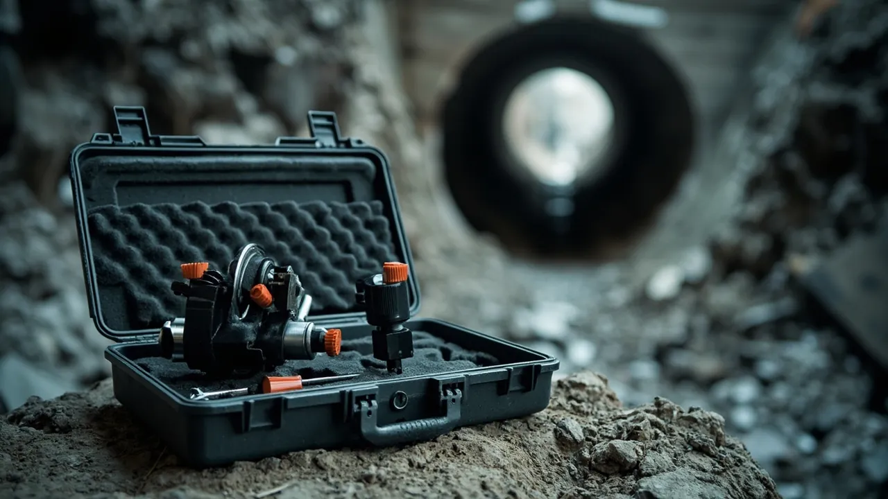
The purpose of a tunnel-boring machine parts case is to deliver disc cutters, rippers, articulation cylinders, thrust cylinders and erector components with their cutting-edge geometry, bearing clearance, sealing-surface quality and hydraulic cleanliness intact after leaving the factory and passing through road haulage, ocean freight and a second transfer at the tunnel portal. TBM spares fail in a way that is both hard to detect and extremely expensive. A chipped cutter ring redistributes load across the whole cutterhead within a short distance of boring. A scored thrust cylinder rod leaks continuously under high pressure and contaminates the hydraulic circuit. A collapsed tail brush causes grout leakage and ground settlement as soon as boring restarts. On arrival these defects often amount to a few millimetres, or a few microns, of damage. At a working face tens of metres underground, any unplanned cutter change means days of delay and a very large shutdown cost.
Transport protection for TBM spares differs from general heavy machinery parts because four conditions stack on top of one another. First, the parts are extremely expensive and lead times are critical. Cutter assemblies, main drive components and hydraulic pumps and motors are long-lead items, and a damaged unit often cannot be replaced within the programme. Second, underground replacement conditions are poor. Cutter changes are performed at the cutterhead face or inside the excavation chamber, with limited space, limited lighting and restricted lifting. A damaged part cannot be repaired in that environment; the whole assembly is replaced. Third, the chain is complex. TBM spares usually reach a temporary yard near the launch shaft first and are then transferred again through a shaft or decline, and handling during this second leg is often more hazardous than the long-haul leg. Fourth, tunnels impose fire requirements on materials. The combustion behaviour of packaging materials used in a confined underground space is directly relevant to work safety.
This article is written for TBM manufacturers and remanufacturers, tunnelling contractors and equipment management teams, cutter and hydraulic component suppliers, and procurement staff on metro, water and utility tunnel projects. It covers cutterhead tools including disc cutters, rippers and scrapers; cutterhead bodies and cutter housings; shield articulation components; hydraulic system components; screw conveyor and soil conditioning components; and tail skin and segment erector components. It includes failure modes, heavy and irregular part retention design, cleanliness control, fire-performance material selection, standards references, comparison tables, a packing standard operating procedure and goods-in verification methods. All figures are industry-typical or empirical; drawings, technical conditions and project regulations always take precedence. JUNZHJIA provides form-fitted insert design for heavy irregular parts, dedicated cutter cradles, sealed dust-control and humidity-control configurations, and OEM/ODM supply with inspection documentation for TBM and underground equipment applications.
Table of Contents
- 1. Why TBM spares cannot use a generic heavy timber crate
- 2. Category map and failure-mode comparison
- 3. Cutterhead tools: disc cutters, rippers and scrapers
- 4. Cutterhead bodies and cutter housings: mounting faces, bolts and hardfacing
- 5. Shield and articulation components: articulation cylinders, seals and yokes
- 6. Hydraulic components: thrust cylinders, erectors and ISO 4406 cleanliness
- 7. Screw conveyor and soil conditioning: wear parts, pumps and valves
- 8. Tail skin and segment erection components: tail brushes, grout plates and grippers
- 9. Retention solutions for heavy irregular parts: cradles, restraints and lifting
- 10. Cleanliness and sealing: ISO 4406, port capping and dust-excluding packaging
- 11. Fire performance and material compliance: UL94 and underground work safety
- 12. Transport test references: ISTA, GB/T 4857, ASTM D4169 and MIL-STD-810H
- 13. Packing standard operating procedure and goods-in verification
- 14. Procurement evaluation and the OEM/ODM customisation path
- Frequently Asked Questions
- Conclusion & Related Reading
1. Why TBM spares cannot use a generic heavy timber crate
TBM spares are large and heavy, so projects often default to the familiar combination of heavy equipment, a timber crate and steel strapping. Applied to TBM components this approach fails, because the acceptance criterion for a TBM spare is not structural integrity. It is "usable underground".
The first reason is that latent damage cannot be repaired underground. The working environment of a TBM removes almost any possibility of on-site rework. A disc cutter bearing with micro-indentation could be replaced on the surface with modest effort; at the cutterhead face, changing a cutter assembly means stopping, clearing the chamber, entering it, and dismantling and refitting, with multiplied schedule and cost impact. A scored articulation cylinder rod could be re-plated in a workshop; underground, the whole cylinder is replaced. The transport specification for TBM spares must therefore target zero latent damage rather than acceptable external appearance.
The second reason is that geometry and assembly relationships are extremely sensitive. The installed height of cutterhead tools, the locating faces of cutter housings and the flatness of the cutterhead body together determine the depth of cut and the load carried by each individual tool. Any deviation causes single-tool overload and, within a short time, cascading damage. The articulation clearances on the shield, the installation angle of the tail brushes and the locating faces of the erector gripper are equally precise relationships. A single transit impact on such a face may amount to only a few hundredths of a millimetre of distortion, yet the consequence is abnormal thrust, loss of steering control or grout leakage.
The third reason is that hydraulic cleanliness is irreversible. TBM hydraulic systems operate at high pressure, high flow, and surrounded by dust and slurry. System cleanliness is normally controlled against the particle contamination classes defined in ISO 4406, with the specific class set by the equipment manufacturer's technical conditions. If cylinders, pumps, motors and valves introduce particles during transport and assembly, no subsequent filter change can wash that contamination out. The only remedy is repeated flushing or an oil change, and changing oil underground is equally difficult.
The fourth reason is that the second transfer is the most dangerous leg. After arrival on site, TBM spares typically pass through a temporary yard, a shaft or decline, and then an underground rail car or flatbed. Lifting conditions are poor, space is restricted, and the operators handling the parts pay less attention to packaging condition than a long-haul carrier would. The packaging design must therefore build in fault tolerance: even after one off-angle lift, one impact or one rough handling event, the part should still be usable.
A field observation that holds up in practice: in TBM spare parts disputes, the costly case is not visible breakage, it is "looks fine, will not run". The core metrics for a packaging scheme should therefore be geometry retention and cleanliness retention, not whether the case itself survived.
Once these four points are understood, it becomes clear why TBM parts cases need dedicated cradles, form-fitted inserts, rigorous sealing and humidity control, and attention to material combustion behaviour. The underlying principles are covered in shock-absorbing case design logic and cushion liner and case base plate coordination.
2. Category map and failure-mode comparison
TBM spares range from seals weighing a few hundred grams to cutterhead components weighing several tonnes. The table below maps typical weight class, primary weak points, dominant failure modes and preferred protection measures.
| Category | Typical weight class | Primary weak points | Dominant failure mode | Preferred protection |
|---|---|---|---|---|
| --- | --- | --- | --- | --- |
| Disc cutters | Medium to heavy (tens to hundreds of kg) | Cutting ring, body bearings, seals | Ring chipping, bearing micro-indentation, seal failure | Vertical cradle plus edge guard ring plus axial retention |
| Rippers and scrapers | Light to medium | Tungsten carbide tips, body | Tip breakage, body distortion | Individual compartments plus tip caps plus anti-mixing controls |
| Cutterhead body and spokes | Very heavy (tonnes) | Mounting planes, housing locating faces | Flatness out of tolerance, locating-face damage | Dedicated fixture plus locating-face guards plus anti-distortion support |
| Cutter housings and wedges | Medium | Locating faces, wedge faces, bolt holes | Locating-face damage, wedge damage | Individual compartments plus face guards plus numbering |
| Articulation cylinders and seals | Heavy | Rod, bore, seal lip | Rod scoring, lip damage | Rod sleeve plus lip guard ring plus port plugs |
| Thrust cylinders and shoes | Very heavy | Rod, spherical end, shoe face | Rod scoring, spherical-end damage | Dedicated cradle plus spherical-end cap plus rod sleeve |
| Erector components: rotation, lift, grip | Medium to heavy | Gripping faces, slew bearing raceway | Raceway indentation, gripping-face damage | Raceway guard plus dedicated cradle plus retention |
| Hydraulic pumps and motors | Medium | Internal clearances, shaft extension, ports | Contamination-induced sticking, shaft damage | Port plugs plus shaft sleeve plus clean packaging |
| Hydraulic valves and manifolds | Light to medium | Spool and seat, port threads | Sticking, internal leakage, thread damage | Individual compartments plus port plugs plus humidity control |
| Screw conveyor flights and casing | Heavy | Flight outer edge, casing liner | Flight edge curling, liner distortion | Dedicated cradle plus edge protection plus anti-roll |
| Soil conditioning and grout pumps | Medium | Rotor and stator, outlet flange | Stator distortion, flange damage | Individual compartments plus flange covers plus dry-run warning marking |
| Tail brushes and grout plates | Light to medium | Bristle direction, wire bundles, plate face | Bristle crushing, plate distortion | Flat storage plus compartments plus no top loading |
| Segment gripper and heads | Medium | Gripping faces, locating pins | Grip-face wear, pin bending | Individual compartments plus pin sleeves |
| Seals and elastomers | Light | Lip, elasticity, shelf life | Lip damage, ageing, permanent set | Dark, cool storage, flat placement, shelf-life control |
| Cutter fasteners and wedge bolts | Light | Threads, mating faces | Thread damage, mixing of grades | Compartmented trays plus labelling plus torque-class marking |
Two rules can be drawn from the table. The first is that cutting edges and mating faces must be absolutely isolated. Disc cutter edges, ripper tips, cutter housing locating faces and articulation mating faces all belong to the "one impact and it is scrap" category, and they must be physically isolated rather than wedged with filler. The second is that very heavy parts are protected by fixtures while precision parts are protected by partitioning. The protection of multi-tonne items such as cutterhead bodies, spokes and thrust cylinders depends on dedicated fixtures and anti-distortion support, whereas valves, seals and fasteners depend on compartments, labelling and clean packaging.
A note on terminology. In practice the terms TBM parts case, cutterhead tool case, shield spare parts case, tunnel equipment case and boring machine parts case are used interchangeably, and enquiries often say only "parts case". The structural and performance requirements differ substantially. A cutterhead tool case for disc cutters and rippers must be built around edge protection and vertical cradles. A shield spare parts case for thrust cylinders and erectors must be built around rod protection and heavy-load retention. A boring machine parts case for hydraulic pumps and valves must be built around cleanliness and port capping. If only the generic term "parts case" is provided, the supplier can only offer a generic solution, and the result is normally under-protected heavy parts and over-designed precision parts. Specify category, weight, centre of gravity and cleanliness class by part-number family in the technical agreement.
3. Cutterhead tools: disc cutters, rippers and scrapers
Cutting tools are the fastest-consuming components on a TBM and carry some of the highest transport protection requirements.
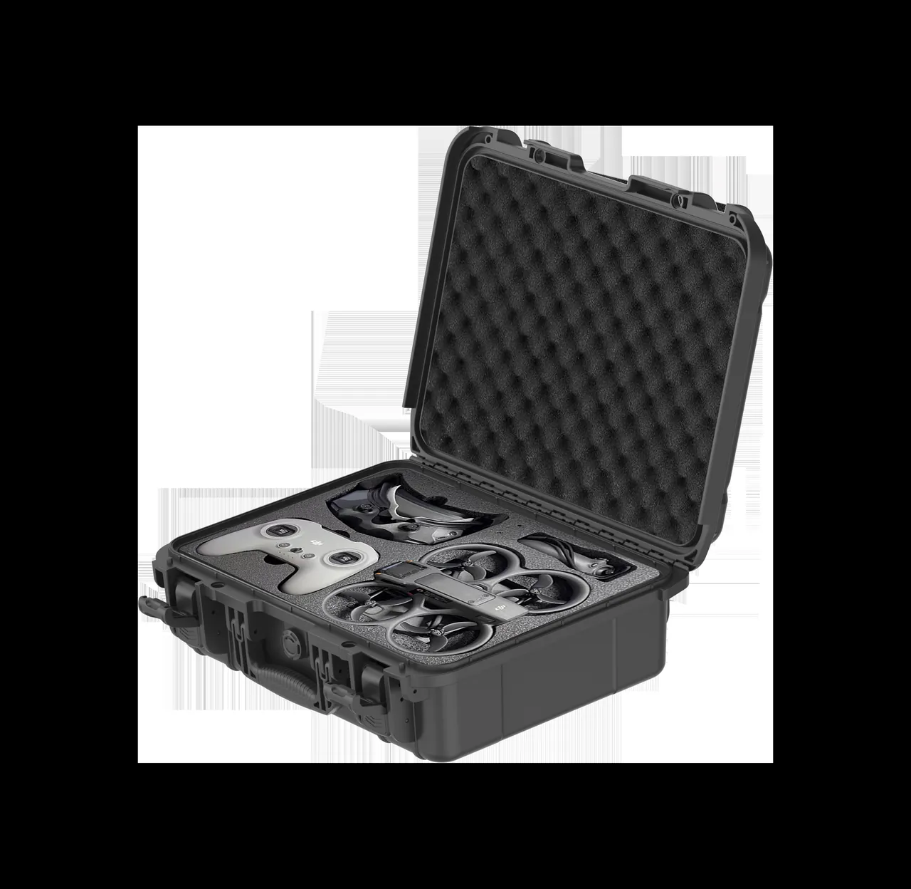
Disc cutters. A disc cutter combines a cutting ring, a body, bearings and seals, and is therefore a precision machine assembly inside a heavy structure. Its two fatal weak points are the cutting ring edge and the internal bearings. Once the edge chips, the penetration and load condition of that cutter changes immediately and neighbouring cutters become overloaded within a short distance. Once a bearing develops micro-indentation, it progresses rapidly to spalling under high thrust and rotation, eventually seizing the assembly. Four packing requirements follow. First, a vertical cradle that keeps the cutter upright, close to its working attitude, with the edge in contact with nothing. Second, an edge guard ring wrapping the entire cutting edge in a compliant or semi-rigid material. Third, axial retention to prevent rolling and end float inside the case. Fourth, bearing-cavity protection, leaving the factory rust-preventive packaging intact and adding desiccant and a humidity indicator card inside the case.
Rippers and scrapers. Rippers with tungsten carbide tips and scrapers are cutting tools whose weak points are the carbide tip and the welded joint on the body. Carbide is brittle, and a single impact can cause breakage or an internal crack that propagates rapidly under boring load. Packing requirements are one tool per compartment, tips facing up or sideways with protective caps, and no mixed stacking. Because these tools are relatively light and numerous, the risk of mixing and mis-installation is high, so numbering and weight verification are essential.
Cleanliness and rust prevention for cutting tools. Disc cutter bearing cavities and seals are extremely sensitive to dust, and TBM tools are typically stored in damp, muddy conditions. Tool packaging must therefore meet both objectives at once: dust exclusion and humidity control. Use vapour-phase inhibitor film as the inner packaging, add desiccant and a humidity indicator card to the case, and keep the package sealed throughout transport and storage. For disc cutters held in long-term inventory, maintain a shelf-life register and inspect seal condition periodically.
4. Cutterhead bodies and cutter housings: mounting faces, bolts and hardfacing
The cutterhead body and cutter housings are the primary load-bearing structures of a TBM, and their protection logic is entirely different from that of the tools: tools fear impact, cutterheads fear distortion.
Cutterhead bodies and spokes. A cutterhead is an integral structure weighing from several tonnes to tens of tonnes. The main transport risk is not local impact but global distortion: an improperly located support creates bending in unsupported spans, and torsional loads in transit can alter cutterhead flatness and the relative positions of the cutter mounting faces. A cutterhead should therefore be transported on a multi-point support fixture that lands on structurally rigid features, typically at spoke roots and main beams, and never on cutter mounting faces. Split cutterheads also require the relative position of each section to be locked so that assembly is not misaligned after transport.
Cutter housings and wedges. The cutter housing is the location datum for the tool, and the accuracy of its locating faces, wedge faces and guide faces is transferred directly to the cutter. Damage to a locating face produces an installed-height error, which in turn causes uneven loading between tools. Packing requirements: protect locating faces with plates or strips; pack each housing together with its matching wedge and bolts as a numbered set; and where the housing has been hardfaced, protect the edge of the hardfacing deposit against chipping.
Hardfacing and composite wear plates. TBM spares make extensive use of hardfaced deposits and composite wear plate such as high-chromium cast iron laminate. The edges and interface of these materials are comparatively fragile and must be protected against local impact and prying. They should also be stored in isolation, because the rough, hard hardfaced surface will score any machined surface it contacts directly.
A design trade-off on "cutterhead parts cases". Because a cutterhead body is enormous, projects rarely build a dedicated case for it. The usual approach is a dedicated fixture and a weatherproof, dust-proof cover for the cutterhead body, combined with partitioned cases for cutters, housings and fasteners. TBM projects therefore typically need a combined scheme: fixtures and covers for large structural items, custom cases for small and medium precision items, and compartmented trays for small parts. JUNZHJIA can supply the insert and case portion of that combined scheme by part-number family, with inserts formed to the actual profile of each cutter housing.
5. Shield and articulation components: articulation cylinders, seals and yokes
The articulation system is what allows a TBM to steer through curves, and the protection focus for its spares is the piston rod, the seal lip and the mating faces at the articulation joint.
Articulation cylinders. Articulation cylinders are typically short-stroke, high-thrust units installed in confined spaces, and the rod and seal lip are the critical weak points. Rod scoring destroys the plating and damages the lip seal, producing continuous leakage. Packing requirements: a rigid rod sleeve, port plugs at both ends of the cylinder body, horizontal support at both mounting ends, and no use of the rod as a support point. Where a cylinder travels with the rod extended, the sleeve must be stiff enough to prevent both bending and axial impact.
Articulation seals and seal rings. Articulation seals, including rubber rings and lip seals, fail through lip damage, ageing and permanent set. Packing requirements: store flat or suspended in the designed attitude, avoid sharp-edge compression, keep away from light and heat, and pack individually. Shelf-life control is critical for rubber seals, and goods-in verification should confirm the production date.
Yokes and spherical ends. Yokes and spherical ends are mating pairs in which the spherical surface and the pin bore are the locating datum. Damage to the spherical surface changes the loading at the articulation point and therefore affects steering control. Packing requirements: a protective cap on the spherical end, a plug over the pin bore, compliant isolation between mating surfaces, and paired packing of yokes.
Fastener and pin control. Articulation hardware is usually high-strength and graded by torque class. Mixing grades is the most common error at this stage and the consequences are serious, because an under-graded bolt can fail under boring load. Store by size and grade in compartments and mark the torque requirement in each compartment.
6. Hydraulic components: thrust cylinders, erectors and ISO 4406 cleanliness
TBM hydraulic systems have very high power density, and the core protection metric for their spares is cleanliness, which follows a completely different logic from that of mechanical parts.
Why cleanliness is the core metric. ISO 4406 uses three codes corresponding to concentrations of particles larger than 4, 6 and 14 micrometres. TBM hydraulic systems operate at high pressure, high flow and in a heavily contaminated environment, and manufacturers usually specify a relatively strict working-fluid cleanliness requirement, with the exact class defined by the technical conditions. The role of packaging is to block the contamination source. Particles introduced by cylinders, pumps, motors, valves and piping during transport and assembly directly reduce the achieved system cleanliness, and that loss cannot be fully recovered by subsequent filtration.
Thrust cylinders and shoes. Thrust cylinders are the main actuators of a TBM: large, long-stroke and with high rod surface quality requirements. Protection requirements: full-length rod sleeve, cap over the spherical end, dedicated cradle support for the body, and a guard plate on the shoe face. For very long cylinders, the number of cradle support points should be determined from length and stiffness so that transport-induced bending and vibration fatigue are avoided.
Erector components. The slew bearing, lift mechanism and gripping mechanism of a segment erector are precision motion components. Slew bearing raceways are highly impact-sensitive, and an indentation caused by a single impact produces periodic noise and increasing clearance during rotation. Protection requirements: a guard plate over the bearing, no direct lifting load applied through the raceway region, guard plates on gripping faces, and sleeves over locating pins.
Hydraulic pumps, motors, valves and manifolds. Clearances in these units are measured in micrometres, and the protection requirements have been established repeatedly in mining and construction machinery applications: plug the ports, sleeve the shaft extension, ensure the housing carries no load, and leave the factory packaging intact. Valve groups mounted on a manifold are usually exposed and protruding, so they need an overall cover or separate compartments. Piping must not be bent below its minimum radius, tube ends need protective caps, and threaded connections need thread protection.
The packaging environment for hydraulic parts. Inner packaging for hydraulic components should be carried out in a clean environment, and insert materials should be selected for low shedding and low dust generation. This is why EVA and PU inserts are generally preferred over ordinary expanded polyethylene in hydraulic applications, where the latter's debris becomes a contamination source.
7. Screw conveyor and soil conditioning: wear parts, pumps and valves
The screw conveyor and soil conditioning system handle highly abrasive muck, so the protection priorities for their spares are wear-surface protection and mating-surface accuracy.
Screw conveyor flights and shaft. The outer edge of the screw flight experiences the most severe wear and is normally hardfaced. The main transport risk is curling and distortion of the flight edge, because the flight is a thin-walled cantilever structure with concentrated loading. Packing requirements: a dedicated cradle matched to the shaft diameter, protective strips along the flight edge, no use of the flight as a load-bearing point, and anti-roll restraint for the whole shaft.
Casing and liners. The wear liner inside the screw conveyor casing is a consumable, and it fails through wear and distortion. A liner is a thin-walled component and is very easily distorted by local compression in transit, which leads to assembly difficulty and accelerated wear. Packing requirements: dedicated vertical or horizontal support, a support ring inside the bore, and no stacking.
Soil conditioning and grout pumps. These are usually progressive cavity or piston pumps, in which the rotor and rubber stator form the core mating pair. The main transport risks for a rubber stator are distortion and ageing, either of which causes poor sealing and reduced flow. Packing requirements: pack the stator separately, preserve its natural shape, avoid long-term compression, and keep it away from light and heat. Outlet flanges need covers, and the pump body should carry essential on-site warning markings such as "do not run dry".
Valves and piping. Valves, check valves and piping in grouting systems should be handled to hydraulic standards: port capping, thread protection, individual compartments and humidity control.
8. Tail skin and segment erection components: tail brushes, grout plates and grippers
Tail skin and erection components are awkwardly shaped and orientation-sensitive, and their protection needs are frequently overlooked.
Tail brushes. A tail brush consists of wire bundles and rubber plates and functions by preventing simultaneous grout and groundwater from passing along the tail skin. Bristle direction and packing density are functional parameters, and once the bristles are crushed or disordered the sealing performance drops sharply. Packing requirements: flat storage, no top loading, no straps tightened directly across the brush body, and support dividers between layers. A complete annular tail brush assembly should be held in shape by a fixture matched to its ring diameter.
Grout plates and articulation protection plates. These are thin plate structures whose main risk is bending and loss of flatness. Packing requirements: flat storage, separate layers with dividers between them, no heavy items on top, and edge protection strips.
Segment erector grippers and heads. The gripping faces and locating pins are functional areas and need guard plates and sleeves. Locating pins are slender and bend easily and must be individually secured. The cylinders and linkage mechanisms of a gripper are moving components and should be protected to hydraulic standards.
Seals and waterproofing materials. Segment gaskets are a classic "crush, light and heat sensitive" category. Their protection and shelf-life requirements are similar to those for tail brushes, and once a gasket takes a permanent set, the waterproofing performance of the assembled ring cannot be guaranteed.
9. Retention solutions for heavy irregular parts: cradles, restraints and lifting
TBM spares include many heavy, large and irregular components, and how these are secured determines whether the whole packaging scheme works.
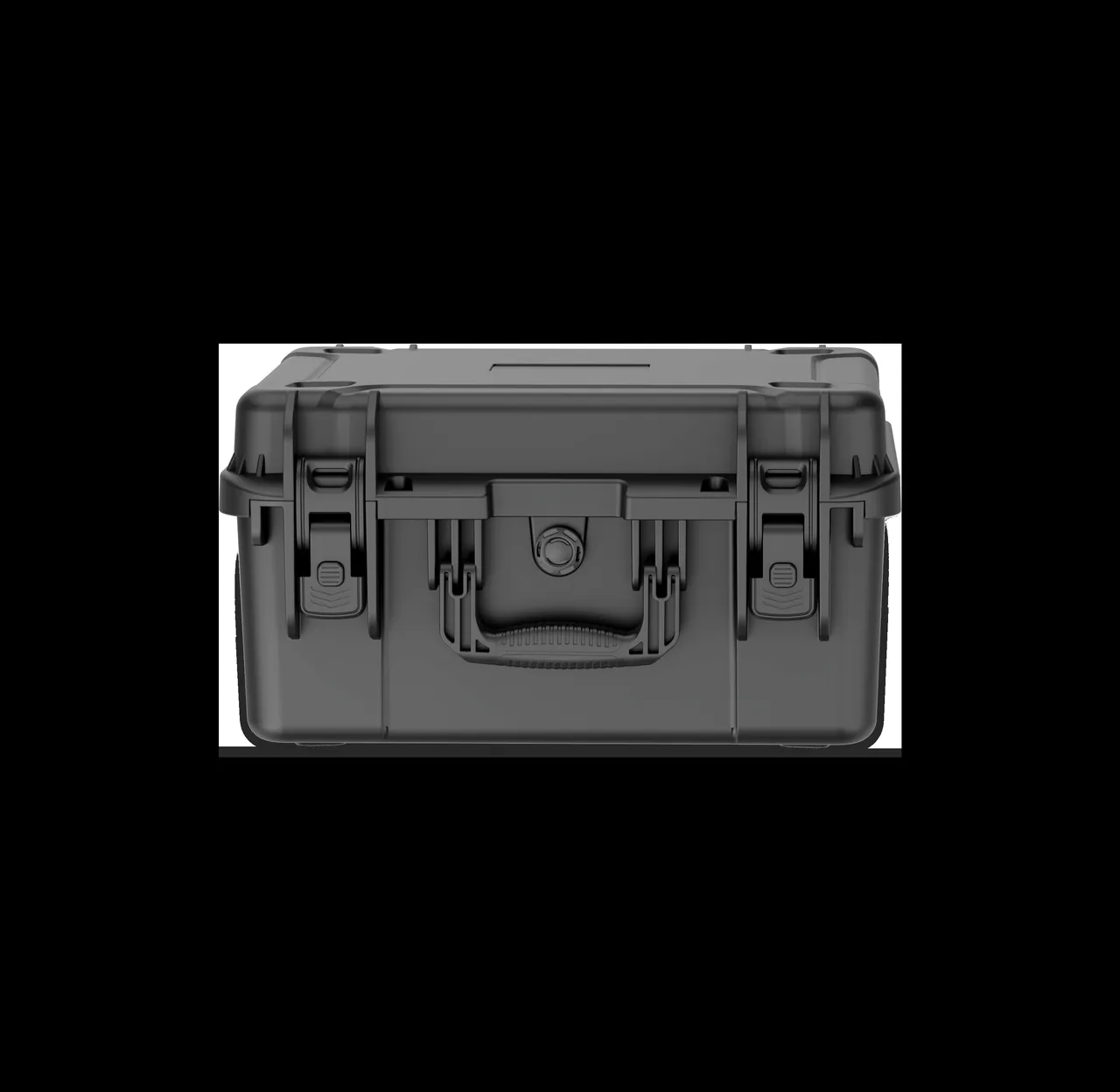
Three principles of cradle design. First, load-bearing points must land on structurally rigid features such as journals, flange roots or casing reinforcing rings, and never on machined faces, cutting edges or thin walls. Second, contact surfaces should have compliant padding so that hard-on-hard contact cannot create indentations or scoring. Third, the cradle must be positively connected to the case floor or pallet, using bolts, keys or wedges, so that the cradle itself cannot shift under vibration.
Restraint in three axes. Horizontally, use blocks and wedges to constrain fore-aft and lateral movement. Vertically, use clamp plates or straps, and straps must pass over rigid features and never across machined surfaces. Cylindrical items such as cylinders, screw shafts and roller-type components require anti-roll provisions. Parts with a high centre of gravity should be stabilised by lowering the centre of gravity or increasing the base footprint.
Lifting and second transfer on site. The second transfer of TBM spares on site is often the most hazardous operation. Design considerations: define lifting points and mark the centre of gravity; leave adequate space for slings so they do not press on the part itself; for components that must not be tilted, mark "do not tilt" and the permissible tilt range on the outside of the case; and provide a dedicated lifting frame for shaft transfers so that lifting forces act on the case structure rather than on the part.
Stacking and load securing. TBM parts cases are heavy and stacking risk is significant. State a stacking limit and use steel strapping or additional stiffening where required. For underground rail or flatbed transport, secure the whole case and account for the longitudinal inertia imposed by track gradients.
A note on extreme temperature and humidity. Tunnels are hot and humid year round, and in some projects the underground temperature exceeds 35 degrees Celsius with relative humidity persistently above 85 percent. This imposes moisture and heat resistance requirements on packaging materials; the approaches described in case design for extreme temperature environments are useful for selecting insert and gasket materials that will not soften, distort or lose elasticity in such conditions.
10. Cleanliness and sealing: ISO 4406, port capping and dust-excluding packaging
For hydraulic, bearing and precision mating components, transport protection is fundamentally a contamination control problem.
A three-layer dust exclusion system. Layer one is component-level capping: plug every oil port, air port and connection, cap every tube end and protect every thread. Layer two is component-level packaging: use rust-preventive film, vapour-phase inhibitor film or foil bags as inner packaging to create a local clean environment. Layer three is case-level sealing: configure the case gasket system to IEC 60529 and GB/T 4208 requirements, aiming for IP6X dust tight in mining and tunnelling environments and IP67 where open storage or water exposure is expected; also fit a pressure equalisation valve to balance the differential caused by temperature swings so that the gasket is not drawn out of position.
Desiccant and humidity indication. TBM spares often remain in storage for months, since launch programmes are measured in months, so humidity control is a long-term task. Size the desiccant according to internal volume and expected storage period, add a humidity indicator card, and establish a periodic inspection and replacement regime, because desiccant stops working once saturated and shows no visible change when it does.
Clean unpacking requirements. Even a genuinely IP6X case loses internal cleanliness if it is opened outdoors in a dusty environment on site. The technical documentation should therefore specify an unpacking environment requirement and state that any part not immediately installed must be returned to the case or covered with a clean drape.
Reliability of sealing and hinge structures. Case opening frequency is high on tunnel sites and handling is rough, so gaskets, hinges and latches must be durable. The relevant structural design is covered in case hinge, latch and seal systems, including gasket joint treatment, hinge load capacity and anti-release latch design.
11. Fire performance and material compliance: UL94 and underground work safety
Tunnels and shafts are confined spaces, and the combustion behaviour of packaging materials is directly relevant to work safety. This is frequently overlooked on TBM projects.
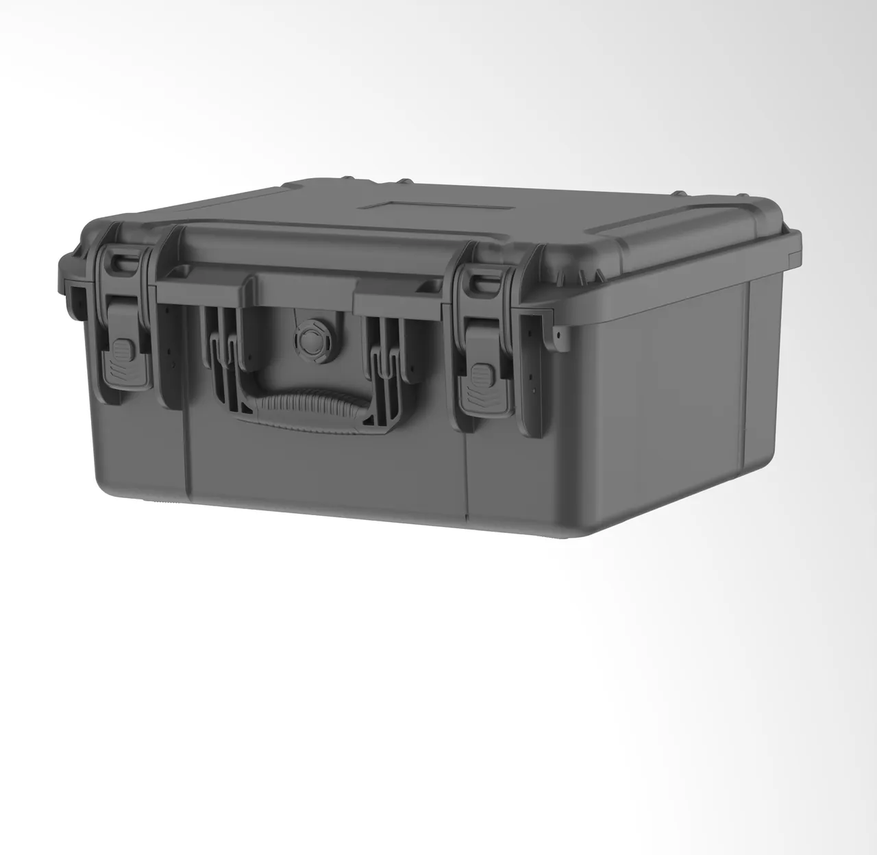
What UL94 means. UL94 is the widely used method for testing the flammability of plastic materials. A V-0 rating indicates that, in the specified vertical burning test, the specimen self-extinguishes within a short time after the ignition source is removed and does not produce dripping material that ignites the underlying cotton. For packaging inserts that will be stored and opened inside a tunnel, near a shaft or in an underground temporary store, specifying a material that meets UL94 V-0 significantly reduces fire risk.
Where fire performance matters. First, insert materials: EVA, PE and PU foams differ considerably in combustion behaviour, and suppliers should be asked for the relevant UL94 test documentation where available. Second, case materials: engineering polymer cases and timber cases behave differently in a fire, and timber represents a substantial fire load underground. Third, packaging ancillaries: bubble wrap, expanded polyethylene, cardboard and desiccant packaging all contribute fire load and must not be ignored when stored in quantity underground.
Supporting site management measures. Material compliance is only the first step. On site, keep the underground temporary storage area at a safe distance from hot work; remove waste packaging promptly and never let it accumulate underground; and collect and dispose of oil-contaminated packaging such as rust-preventive paper and cloth separately.
Other compliance notes. Packaging for sea export must satisfy wood packaging quarantine requirements, for example by using fumigation-free plywood or treated timber. Spares classified as dangerous goods, such as components containing oil or batteries, must be handled under the applicable transport regulations. Any compliance conclusion should follow the regulations of the project location and the requirements of the carrier.
12. Transport test references: ISTA, GB/T 4857, ASTM D4169 and MIL-STD-810H
The credibility of a packaging scheme comes from test data. The following frameworks are commonly used for TBM parts cases.
ISTA procedures. Published by the International Safe Transit Association, these procedures are graded by transport mode and package weight and are built around real distribution chains, which makes them suitable for validating a package along a specific route. Export projects frequently require an ISTA procedure as the baseline packaging validation; see ISTA transport testing procedure explained.
The GB/T 4857 series. These Chinese standards define basic test methods for transport packages, covering vibration, impact, drop, stacking and compression. This is the most commonly cited framework for domestic transport packaging validation and suits domestic project acceptance; see GB/T 4857 transport packaging testing essentials.
ASTM D4169. This standard organises test sequences by distribution cycle and emphasises combining tests according to the actual distribution stages. It is frequently used for North American projects; see ASTM D4169 distribution cycle testing.
MIL-STD-810H, with an important non-military note. The vibration, shock, temperature and humidity, mould and salt fog methods in this standard are widely used by industry as a methodological basis for environmental testing. It must be stated clearly that citing MIL-STD-810H means only that its test methods are adopted; it does not imply any military certification and does not place the product on any military list.
A recommended test sequence for TBM spares. Because TBM spares pass through two distinct legs, namely long-haul transport and shaft transfer, the recommended sequence is: temperature and humidity preconditioning, random vibration, shock or drop, lifting and off-angle lift simulation, vibration again, then unpacking inspection and functional verification. Acceptance criteria should cover three layers: packaging integrity, part geometry and appearance, and part function and cleanliness. Because TBM spares are heavy, the load capacity and fatigue strength of fixtures and cradles should also be verified.
Reminder: every test conclusion is bound to a specific packaging configuration, payload weight and set of test parameters. A "passed testing" statement without those parameters has no engineering meaning.
13. Packing standard operating procedure and goods-in verification
A recommended packing SOP is as follows:
- Part confirmation: verify part number, quantity, weight and factory packaging condition, and record whether the rust-preventive packaging is intact.
- Weak-point marking: mark cutting edges, locating faces, piston rods, spherical surfaces and seal lips as areas that must not carry load, following the drawing.
- Cleanliness check: confirm freedom from dust, swarf and moisture; hydraulic ports must remain plugged.
- Fixture and cradle assembly: install and secure the cradle to the case floor or pallet, confirming that load-bearing points land on rigid features.
- Insert assembly: fit the form-fitted insert, confirm recesses match the part, and check for sharp corners or hard protrusions.
- Part placement: place heaviest to lightest and bottom to top; a heavy part must be fully restrained before the next part is added.
- Retention and fixing: constrain all three axes with blocks, wedges, clamp plates or straps, keeping straps off machined surfaces.
- Humidity control: add desiccant and a humidity indicator card, and record quantity and location.
- Closing and seal inspection: check gasket continuity and compression, pressure equalisation valve condition, and hinge and latch function.
- Marking and records: apply centre-of-gravity, this-way-up, do-not-tilt, keep-dry and stacking-limit markings, photograph the case and complete the packing record sheet.
- Lifting and dispatch: lift from the marked points and confirm the case is secured on the transport unit.
Goods-in verification should follow a three-layer criterion:
- Layer one, the package. Check for case deformation, gasket failure, humidity indicator colour change, desiccant saturation, signs of water or contaminant ingress, and displacement of fixtures or cradles.
- Layer two, appearance and geometry. Check cutting edges for chipping, locating faces for impact damage, piston rods for scoring, spherical ends and pin bores for damage, and threads and ports for condition. Sample-check critical dimensions such as cutterhead mounting-face flatness and cutter housing locating-face height.
- Layer three, function and cleanliness. Check disc cutter rotation by sound, feel and clearance; check port contamination on hydraulic parts; check slew bearing rotation; check elastomer hardness and appearance. Apply a sampling plan where necessary; methods are discussed in custom case acceptance and AQL sampling.
Claims and traceability. The packing record sheet should capture part number, packing date, packer, fixture reference, insert reference, desiccant quantity and photograph references. Latent damage disputes on TBM spares involve high values and difficult proof, and a complete packing record is often the only effective basis for allocating responsibility.
14. Procurement evaluation and the OEM/ODM customisation path
A recommended procurement scorecard:
| Evaluation dimension | Key questions | Suggested weight |
|---|---|---|
| --- | --- | --- |
| Heavy irregular part design | Has the supplier designed cradles for cutterhead tools or large cylinders? | High |
| Insert precision and form-taking | Can inserts be formed from physical parts or 3D data? How are tolerance and handling clearance controlled? | High |
| Sealing and dust class | Is IP6X or IP67 stated explicitly? What is the gasket construction and joint treatment? | High |
| Material fire performance | Can UL94 test documentation be provided for inserts and case materials? | Medium |
| Cleanliness and humidity package | Desiccant sizing, humidity indicator cards, pressure equalisation valves? | Medium |
| Standards and documentation | Are IP and vibration test reports available? | Medium |
| Delivery and capacity | Lead time, batch consistency, fixture and tooling investment? | Medium |
| Service life and spares | Gasket replacement, wear-part supply, expected case life? | Medium |
The OEM/ODM customisation path. For TBM manufacturers and remanufacturers, cutter suppliers and tunnelling contractors, the customisation route is recommended: the supplier proposes a protection scheme and a sample case by part-number family, the scheme is trialled within a pre-launch spare parts batch, and full deployment follows validation. The value of customisation is that it converts packaging from a consumable into a reusable asset, since a custom case with replaceable inserts can serve multiple projects and maintenance cycles. Cost evaluation methods are covered in custom case mould cost analysis and how to choose a protective case OEM factory.
JUNZHJIA capability note. For TBM and underground equipment applications, the manufacturer provides three categories of support. First, form-fitted inserts and cradles for heavy irregular parts, formed from drawings, 3D data or physical parts, with isolation and sleeve solutions for cutting edges, locating faces and piston rods. Second, sealing, dust-control and humidity-control configuration to IP6X or IP67 requirements, including pressure equalisation valves, desiccant and humidity indicator cards, together with material fire-performance documentation. Third, OEM/ODM and documentation, with customised branding and marking plus packing work instructions and supporting inspection records. The final scheme must follow the part drawing, weight and centre-of-gravity data and the regulations of the project location.
Frequently Asked Questions
Q: Why must TBM cutting tools be packed vertically? Is flat packing with filler not more space efficient?
A: Disc cutters and rippers are precision machine assemblies inside heavy structures, and their two fatal weak points are the cutting edge and the internal bearings, which flat packing threatens simultaneously. First, when a cutter lies flat its edge orientation is uncontrolled, and once the filler compresses it presses the edges of adjacent cutters directly against one another. Carbide and hardened cutting rings are brittle, so a single edge-to-edge contact can chip the ring or initiate an internal crack that propagates rapidly under boring load. Second, when a cutter lies flat its own weight transfers through the body into one localised region of the bearing, and prolonged static loading leaves an indentation on the raceway. That indentation feels normal during a surface inspection but develops into spalling and seizure after installation. A vertical cradle keeps the cutter close to its working attitude, wraps the edge in a guard ring that contacts nothing, restrains axial movement, and transmits weight through the cradle to rigid features. Vertical packing does take more space, but compared with the shutdown cost of a single underground cutter change, that trade is easily justified. Cutter tool case design should therefore treat correct attitude as the first principle.
Q: What is the fundamental difference between protecting a cutterhead body and protecting cutting tools?
A: The difference lies in the failure mode: tools fear impact, cutterheads fear distortion. Tool failure is local and point-like, and one impact can destroy a cutter, so the protection method is isolation, guard rings and compartments. A cutterhead body is an integral structure weighing several to tens of tonnes, and its failure is global and distributed. An improperly located support creates bending in unsupported spans, and torsional loads during transport change cutterhead flatness and the relative positions of the cutter mounting faces. Once flatness is out of tolerance, every cutter can be individually perfect and the machine will still overload individual tools and cut unevenly. A cutterhead should therefore travel on a multi-point support fixture located at rigid features such as spoke roots and main beams, and never on cutter mounting faces. Split cutterheads must also have the relative position of each section locked. In addition, projects rarely build a case for the cutterhead body itself; the usual approach is a dedicated fixture with a weatherproof and dust-proof cover, concentrating case resources on cutters, housings and fasteners, which makes the overall scheme more economical.
Q: Why is ISO 4406 cleanliness so important for TBM hydraulics, and how much can packaging really contribute?
A: ISO 4406 uses three codes corresponding to concentrations of particles larger than 4, 6 and 14 micrometres. TBM hydraulic systems operate at high pressure, high flow and in a heavily contaminated environment, and manufacturers normally specify a relatively strict working-fluid cleanliness requirement, with the exact class defined by the technical conditions. Packaging contributes more than most buyers expect, because the main particle ingress path occurs before assembly: dust and swarf inside the case, port plugs removed too early, scored piston rods and threads, and ambient dust during open-air unpacking all introduce contamination before the part reaches the system. That loss is irreversible. A filter can only passively intercept particles already in the circuit; it cannot wash contamination out. The only remedy is repeated flushing or an oil change, and changing oil underground is equally difficult. For thrust cylinders, articulation cylinders, pumps, motors, valves and manifolds, the full three-layer system must be maintained: component-level capping, component-level inner packaging, and case-level sealing, with inner packaging carried out in a clean environment.
Q: Tail brushes and segment gaskets are only rubber parts. Why are the packing requirements so strict?
A: Because both are functional shape components whose performance depends on shape and orientation, not only on material. A tail brush works because of the direction and packing density of its wire bundles; once the bristles are crushed or disordered it can no longer prevent simultaneous grout and groundwater from passing along the tail skin, and the consequences include grout leakage, ground settlement and, in the worst case, a seized shield. A segment gasket works because of the rebound behaviour of its profile under compression; if it takes a permanent set in transit or storage, the waterproofing performance of the assembled ring cannot be guaranteed. The packing requirements can be summarised as three prohibitions and one obligation: no top loading, no straps tightened directly across the body, no long-term storage under compression, and storage in the designed attitude, which means tail brushes flat on support dividers and annular assemblies held in shape by a matching fixture. They must also be kept away from light and heat, with a shelf-life register and first-in-first-out control, because rubber ages over time regardless of whether it is being transported.
Q: Does underground work impose fire requirements on packaging materials, and how should UL94 be applied?
A: Yes, and this requirement is frequently overlooked on TBM projects. Tunnels and shafts are confined spaces in which smoke extraction and evacuation are difficult, so packaging materials stored and opened underground represent a real fire load. UL94 is the widely used flammability test method for plastics, and a V-0 rating indicates that in the specified vertical burning test the specimen self-extinguishes within a short time after the ignition source is removed and does not produce dripping material that ignites the cotton below. Three practical steps follow. First, ask insert suppliers for UL94 test documentation for EVA, PE and PU foams where available and prefer materials with better combustion behaviour. Second, on case material, timber represents a substantial fire load underground and engineering polymer cases are preferable in most situations. Third, manage packaging ancillaries, since bubble wrap, expanded polyethylene, cardboard and oil-contaminated packaging accumulate in tunnels and should be removed promptly and disposed of separately. Final compliance conclusions should follow the regulations of the project location.
Q: How should the IP rating be chosen for a TBM parts case? Is IP67 always better than IP65?
A: No, the goal is the best match to the environment rather than the highest number. Ingress protection is defined by IEC 60529, with GB/T 4208 as the corresponding Chinese standard; the first digit covers solid foreign objects and dust, the second covers water. The primary threat to TBM spares is dust and slurry, so the first digit must be 6, that is IP6X dust tight; the water digit is then selected according to storage and transfer conditions. IP65 suits surface yards, temporary stores and general underground transfer, while IP67 suits water crossings, long-term open storage or loading in heavy rain. IP67 is not universally better: tighter sealing usually means higher opening resistance and stricter gasket maintenance, and where the case is opened frequently and handled roughly the gasket may actually fail sooner. Two further points matter. First, a fully sealed case develops a pressure differential as temperature changes, so a pressure equalisation valve should be fitted or the gasket may be drawn out of position. Second, even an IP6X case loses internal cleanliness if it is opened in a dusty outdoor environment, so the operating procedure must include an unpacking environment requirement.
Q: TBM spares undergo a second transfer through a shaft or decline on site. How should the packaging design account for that?
A: The second transfer is often the most hazardous leg of the whole chain, because lifting conditions are poor, space is restricted, gradients are steep, and operators usually pay less attention to packaging condition than a long-haul carrier. The approach is to build fault tolerance into the scheme. First, define lifting points and mark the centre of gravity, and ensure that lifting forces act on the case structure rather than on the part, so slings cannot press directly on cutting edges, piston rods or machined faces. Second, provide a dedicated lifting frame for shaft transfers and use four-point lifting where necessary to keep the case level. Third, for components that must not be tilted, mark "do not tilt" and the permissible tilt range on the case exterior, and restrain the part inside the case against tipping so that brief tilting cannot displace it. Fourth, secure the whole case for underground rail or flatbed transport and account for longitudinal inertia from track gradients, adding anti-slip features to the case base where necessary. These measures keep the part usable even after one off-angle lift or one impact.
Q: TBM spares are often stored for long periods. How should long-term protection be handled?
A: Long storage shifts the priority from anti-vibration to corrosion prevention, ageing prevention and deformation prevention. Four measures are recommended. First, use a layered rust-prevention strategy: factory oil or film as layer one, vapour-phase inhibitor film as layer two, and in-case humidity control as layer three, with no layer removed early. Second, make humidity control sustainable by sizing desiccant and humidity indicator cards to internal volume and expected storage period, and establish a periodic inspection and replacement regime, because saturated desiccant shows no visible change yet is completely ineffective. Third, manage elastomers separately: articulation seals, tail brush rubber plates, segment gaskets and progressive cavity pump stators all carry ageing or deformation risk, so store them dark, cool and flat and enforce first-in-first-out. Fourth, prevent creep in heavy parts by supporting long cylinders and screw shafts horizontally at multiple points so that they cannot bend while suspended. The case itself also needs periodic inspection of gasket condition during long storage, which is commonly overlooked.
Q: We buy disc cutters, cylinders and hydraulic valves together. What is a reasonable way to control packaging cost?
A: Use tiered configuration on a shared platform rather than developing a separate case for every category. Three tiers work well. Tier one, heavy irregular parts such as cutter assemblies, thrust cylinders, articulation cylinders and slew bearings: use custom fixtures and cradles, with case size set by the largest part and the lifting requirement, and fixtures and retention blocks made per part number. Tier two, small and medium precision parts such as hydraulic valves, manifolds, gripper heads and cutter housings: use a standard case platform with replaceable form-fitted EVA inserts, adapting to different part numbers by changing the insert. Tier three, light and small parts such as seals, fasteners and wedge bolts: use compartmented trays in standard returnable boxes, with emphasis on labelling and quantity verification. All three tiers share the same sealing system, latches and lifting standards, which substantially reduces tooling investment. If an enquiry quotes only the generic term "TBM parts case", the supplier can only offer a generic solution, and the result is usually under-protected heavy parts and over-designed precision parts. Specify category, weight, centre of gravity and cleanliness class by part-number family in the technical agreement.
Conclusion & Related Reading
Transport protection for TBM components is fundamentally about moving the constraint of "cannot be repaired underground" upstream into the packaging stage. Whether a part is fixed in the correct attitude, whether cutting edges and mating faces are effectively isolated, and whether hydraulic parts sit in a clean, dry environment directly determine how long they will last at the working face. For disc cutters and rippers, the priority is the edge guard ring, the vertical cradle and bearing-cavity humidity control. For cutterhead bodies and housings, it is multi-point support fixtures and locating-face protection. For articulation and thrust cylinders, it is rod sleeves, spherical-end caps and three-axis restraint. For every hydraulic component, the shared baseline is end-to-end ISO 4406 cleanliness control, IP6X sealing and sustainable humidity control. Because tunnels are confined spaces, packaging materials must also meet the applicable fire-performance requirements.
The implementation path has four steps. First, map categories and failure modes by part-number family, separating heavy irregular parts from precision parts. Second, fix fixtures and protection classes, defining load-bearing points, restraint method, IP class and humidity-control scheme. Third, validate by testing, using a combination drawn from ISTA, GB/T 4857, ASTM D4169 or MIL-STD-810H methods and adding lifting and off-angle lift simulation. Fourth, establish a packing SOP and goods-in acceptance criteria so that the scheme is actually executed on site. JUNZHJIA can support all four steps with form-fitted inserts and cradles for heavy irregular parts, sealing and humidity-control configuration, and OEM/ODM supply with inspection documentation.
Related Reading