


The productivity of a turret punch press comes from the marriage of turret and tooling. Dozens of stations ride on a rotating turret, the program selects a station, and a shape change completes in seconds. The weak point in that system is not the machine but the tooling itself. Upper and lower dies sit with clearances measured in hundredths of a millimetre, cutting edges are precision ground, and guide sleeves locate on guide pins with micron-level fits. Once removed and packed into a case, they become a collection of parts that look rugged but behave like brittle instruments. One mixed load, one missing item or one numbering error can cost several hours of downtime and a whole batch of scrap.
The JUNZHIJIA position on turret punch tooling cases is that pairing and numbering deserve the same protection as the cutting edge. Tooling value lies not in individual pieces but in which punch belongs with which die and which station it serves. A chipped edge can be reground, but if punches and dies are separated from their partners, spring clamps go missing and station numbers become confused, the whole changeover system degrades for a long time. A case therefore has to do three things at once: protect the edges, lock the pairing, and control the numbering.
Table of Contents
- Turret Die Edge Chipping: From Edge Radius to Compartment Clearance
- Punch and Die Pairing: One Set, One Compartment, Traceable Numbers
- Spring Clamps and Return Springs: Keeping Small Parts from Disappearing
- Turret Station Numbering: Mapping Machine Stations to Case Slots
- Heavy-Duty Compartments and Indexed Slots: Grading by Station Weight
- Angle Dies and Forming Dies: Cutting Cavities for Irregular Shapes
- Guide Sleeves and Guide Pins: Preserving the Fit Clearance
- Stripper Plates and Polyurethane Springs: Deformation Control and Load Release
- Heavy-Case Load Paths and Forklift Handling: Base Structure Design
- Edge Corrosion and Oil Film Management on Tool Steel Dies
- Transport and Stacking Tests: A Test Plan for Heavy Tooling Cases
- Handover and Station Reconciliation: Making Number Checks Work on the Floor
- Frequently Asked Questions FAQ
- Conclusion and Related Reading
Turret Die Edge Chipping: From Edge Radius to Compartment Clearance
Turret punch tooling edges are more fragile than their appearance suggests. The shearing load during punching is large but predictable in direction, while the loads during transport arrive from every direction and often pass through unsuitable contact points.
Edge chipping arises through three mechanisms. The first is foreign-particle lapping: liner debris, grit or metal swarf trapped between edge and liner forms a lapping pair under vibration and abrades a fine chip line. The second is point-contact crushing: an edge pressed by a hard stop, or by the body of another die, sees contact stress far above yield and takes a notch. The third is relative sliding: a die not fully restrained inside its compartment walks along the channel under vibration while the edge is dragged repeatedly across liner fibres.
All three point to one design conclusion. The cutting edge must float, must never be pressed, and must never move. Compartment clearance becomes the critical parameter. Too tight, and removing or inserting the die scrapes the edge. Too loose, and the die rattles. The working approach is to size the compartment to the die envelope plus 0.3 to 0.5 mm, then fill that clearance with a compressible soft facing that holds the die without crushing it, so the tool can neither move nor be pinched.
| Chipping mechanism | Typical damage form | Main cause | Design countermeasure |
|---|---|---|---|
| --- | --- | --- | --- |
| Foreign-particle lapping | Fine chipping along the full edge | Liner debris, abrasive residue | Low-shedding liner, clean before packing |
| Point-contact crushing | Local notch, rolled edge | Hard stop pressing the edge | Move the load to the die body |
| Relative sliding | Continuous one-direction chipping | Die not fully restrained | Soft hold-down strip or clamp |
| Mutual impact | Irregular chipping | Punches and dies not paired | Fix as sets, never loose |
Punch and Die Pairing: One Set, One Compartment, Traceable Numbers
Turret tooling has one defining property: it is used as a set. A punch pairs with a die, and the clearance between them is established by matched grinding at manufacture. Once mixed, even nominally identical sizes may no longer present the same clearance, and the result is heavier burrs, faster wear, possible jamming and occasionally edge fracture.
Pairing discipline translates into packaging in two layers. The physical layer keeps a matched punch and die in one compartment, separated by a soft divider at least five millimetres thick that never touches either cutting edge. The information layer labels each compartment with the set number, the size, the station it normally serves and the sheet thickness range, using a numbering convention identical to the tool numbers in the machine program.
| Management layer | Carrier | Content | When updated |
|---|---|---|---|
| --- | --- | --- | --- |
| Physical pairing | Shared compartment | Punch and die together, soft divider | Every pack |
| Slot label | Oil-resistant label | Set number, size, thickness range | On change |
| Case inventory | Paper or card | Full tooling list and station map | Each batch |
| Machine mapping | Program tool table | Case numbers against program numbers | On program change |
One practice deserves special warning: borrowing. On the shop floor it is common to combine a punch from one set with a die from another for a short run. If the case is packed from the current state without a record, that mismatched combination can become permanent. A pairing check before every pack, with the result written on the case inventory, creates the traceability that prevents it.
Spring Clamps and Return Springs: Keeping Small Parts from Disappearing
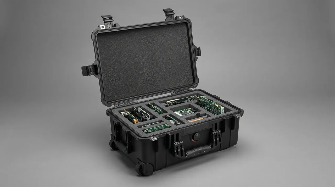
Sheet clamps and die return springs are classic small components, and they are the items most often lost during packing. They share the same profile: small, numerous, inexpensive individually, yet the absence of a single one can stop the machine.
There are three reasons they vanish. Loose storage means parts are tipped out of a bag and dropped. Leaving them attached to the machine means vibration during transport works them loose and they fall somewhere in the crate or on the floor. And with no baseline count, nobody notices a loss until changeover.
The countermeasure is one part, one position, one number, one list. Each small part gets its own pocket machined to suit it, so retrieval requires a light pull rather than emptying a bag, which sharply reduces the drop rate. Each pocket is labelled with the part number, the parent die set and the expected quantity. The case carries a small-parts list showing required and spare quantities. Springs need one extra rule: the pocket must allow the spring to sit at its free length, because a spring stored compressed takes a permanent set.
Clamps deserve a specific note because they are the most expensive item in this group and the most awkward to replace. A clamp left on its machine mount will loosen under vibration and can fall into the scrap conveyor or onto the floor, where it is often not noticed until the next job is set. Removing clamps before shipment and giving them a dedicated pocket with a quantity label is the single most effective change most shops can make, and it costs almost nothing to implement.
| Small part | Typical quantity | Consequence of loss | Anti-loss design |
|---|---|---|---|
| --- | --- | --- | --- |
| Sheet clamp | 4 to 12 | Machine cannot grip, immediate stop | Individual pocket plus quantity label |
| Return spring | 1 to 4 per set | Stripping fails, jamming | Free-length pocket |
| Polyurethane spring | 1 to 2 per set | Abnormal stripping force | Pocket that cannot compress it |
| Locating dowel | 2 to 4 per set | Punch and die lose alignment | Stored as matched pairs |
| Fasteners | Several per set | Assembly interrupted | Small partitioned box plus list |
Turret Station Numbering: Mapping Machine Stations to Case Slots
Numbering confusion is the biggest single killer of changeover efficiency on a turret punch press. The machine numbers its stations, for example A, B, C and D, the tooling carries its own set numbers, and the program uses tool numbers. If those three systems are not reconciled on the packaging itself, operators end up relying on memory and trial fitting.
The packaging answer is a fixed one-case-one-table mapping. A station cross-reference table goes on the inside of the lid, listing machine stations across one axis and the set numbers and sizes normally used at each station down the other, with program tool numbers in a notes column. Each compartment label carries the set number as its primary field and the usual station number as its secondary field. Packing follows the table, retrieval follows the labels, and two actions align the whole numbering system.
For larger tooling stores, digitise the mapping. The case becomes the storage unit for its dies, so a QR code or RFID tag on the side gives instant access to the contents list, the last station used, the number of regrinds and the next inspection date. That approach is described in asset QR code tracking for cases, and it converts a paper ledger into a record that can be queried on the spot.
| Numbering system | Owner | Typical form | Where it appears on the case |
|---|---|---|---|
| --- | --- | --- | --- |
| Station number | Machine turret | A, B, C, D or 1 to 32 | Station table, horizontal axis |
| Die set number | Tooling itself | Stamped or laser marked | Primary field on slot label |
| Program tool number | NC program | T01 to T99 | Notes column in station table |
| Regrind sequence | Tooling file | Suffix R1, R2 | Secondary label field |
Heavy-Duty Compartments and Indexed Slots: Grading by Station Weight
Turret tooling spans a wide weight range. A small round die may weigh barely a kilogram, while a large forming die or a thick-material die can exceed fifteen. Applying one compartment scheme to both means either heavy dies crushing the dividers or light dies rattling in oversized slots.
The answer is to grade. Divide tooling into three or four weight classes and give each a different slot type and restraint method. Light tooling needs thin dividers and soft facing. Medium tooling needs thicker dividers plus hold-down blocks and corner stops. Heavy tooling needs its own compartment, hard stops, a load-bearing base and dividers that land on case structure rather than being inserted into foam. The same grading logic appears in nut and bolt tooling cases, where mass and edge fragility drive the compartment layout.
| Weight class | Unit mass | Divider | Restraint | Base treatment |
|---|---|---|---|---|
| --- | --- | --- | --- | --- |
| Light | Under 3 kg | 3 to 5 mm board | Soft facing plus soft strip | Flat liner |
| Medium | 3 to 8 kg | 5 to 8 mm board | Hold-down block plus corner stops | Thicker liner |
| Heavy | 8 to 15 kg | 8 to 12 mm, floor-supported | Hard stops plus strapping | Load-bearing block to structure |
| Very heavy | Over 15 kg | Separate case or frame | Bolted down | Metal or high-strength plastic pallet |
Indexed slots are the other essential feature of a heavy tooling case. An indexed slot is a recess in the case floor machined to match the die outline so that the tool drops into its designed position without adjustment. The benefit is not only location. It transfers horizontal load directly into the case floor structure instead of letting dividers take the shear. For heavy dies, slot depth should be at least fifteen percent of die height, with a chamfered mouth to guide insertion.
Angle Dies and Forming Dies: Cutting Cavities for Irregular Shapes
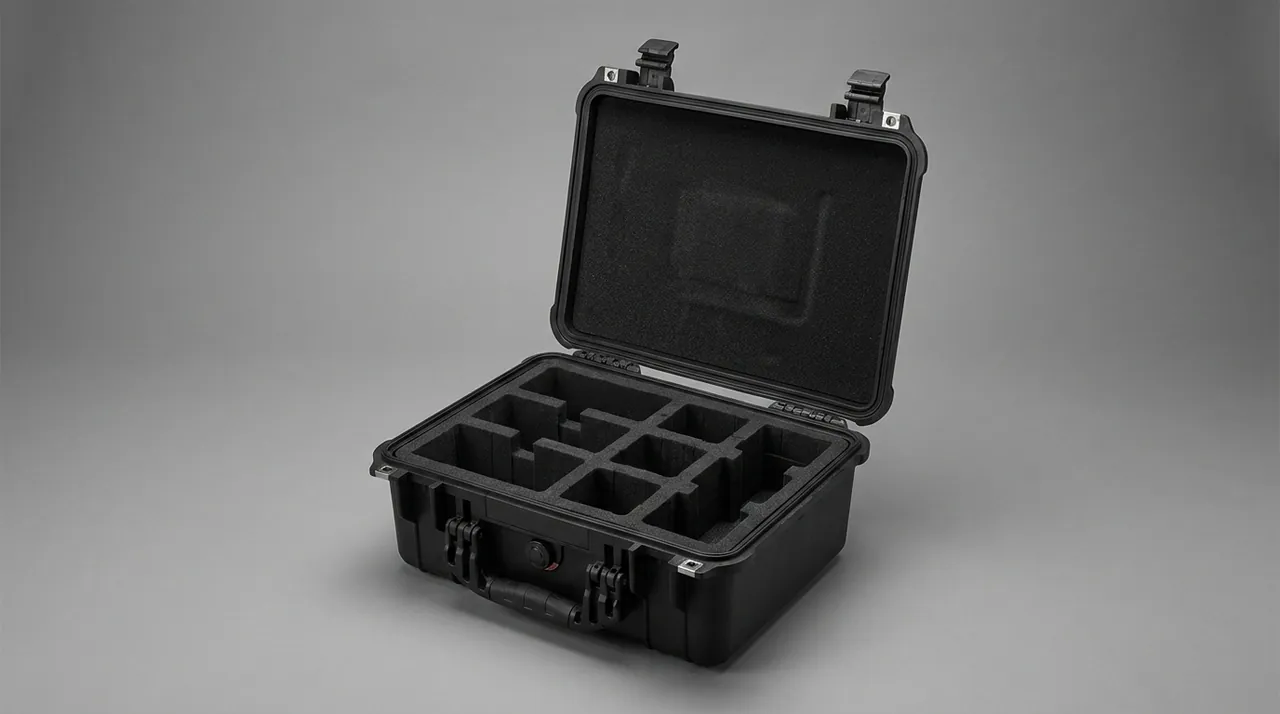
Turret tooling is not only round. Angle dies, louvre dies, ribbing dies and flanging dies have complex, asymmetric outlines, and they place different demands on liner cavity cutting.
Three process routes are available. CNC machining of a solid cavity from EVA or PE board gives high accuracy and good repeatability, which suits volume custom work. Assembled construction from standard board pieces costs less but leaves seams that trap debris. Thermoforming presses sheet into a cavity that follows the shape, which suits curved, complex parts.
Choose by volume and precision: CNC for one-offs and small batches, assembled construction for medium batches with regular shapes, thermoforming for complex curved geometry. Whichever route is used, one rule governs: the cavity support must land on non-functional surfaces such as the die body flank, the flange or a process boss, and must never touch the cutting edge, a forming surface or a guide face.
Asymmetric dies such as angle dies also need attention to centre of gravity and anti-tip behaviour. The cavity should provide sufficient bearing area beneath the centre of gravity projection, and where necessary a removable ballast block inside the cavity keeps the die from tipping during handling.
Guide Sleeves and Guide Pins: Preserving the Fit Clearance
Punches and dies align through guide sleeves on guide pins, with clearances typically between a few microns and about ten. That clearance sets the coaxiality of the pair and therefore the quality of the sheared edge. Once it changes through impact damage, the tooling has to go back to the maker for re-matching or replacement of the guide elements.
Guide elements face two main risks. Guide pins bend: they are slender, and if a die rests on its pin or the pin takes a side load, it will bow, and even a few tens of microns of bow redistributes the clearance. Guide sleeve bores score: chips or grit entering the bore gall the surface during assembly.
The countermeasures are consistent. A die must rest on its proper support, normally the lower die base or the die holder flange, so the pins and sleeves carry nothing. Sleeve bores should be closed with a protective plug, soft plastic, with no hard edges. For separable guide assemblies, the pin and sleeve should be paired and packed together, never mixed with other tooling.
| Guide element | Fragile feature | Dominant failure | Protection |
|---|---|---|---|
| --- | --- | --- | --- |
| Guide pin | Straightness over full length | Bending | Non-load-bearing position plus side stops |
| Guide sleeve | Bore surface | Scoring, galling | Protective plug |
| Ball cage sleeve | Ball retainer | Ball loss | Plug plus shock-absorbing liner |
| Die holder flange | Mounting face | Indentation | Face down on a flat support |
Stripper Plates and Polyurethane Springs: Deformation Control and Load Release
Stripper plates and polyurethane springs are the flexible members of a die. The stripper frees the sheet from the punch after shearing, and the polyurethane spring furnishes the stripping force. Both are most at risk from sustained compression during transport.
Polyurethane springs fail through compression set. Held compressed for a long period, the material loses part of its resilience, and after assembly the stripping force is insufficient, which shows up as the sheet being lifted by the punch, jamming, or damage to the workpiece. Before packing, confirm that the stripper is not under load, in other words that there is a gap between punch and die. Where the construction prevents that, insert a limit block of the correct thickness between punch and die so that spring compression stays under ten percent of free length.
The stripper plate itself is a thin plate and deforms easily. If it carries load in the case, or is supported unevenly, its flatness changes and the clearance to the punch becomes uneven after assembly, producing local scoring. It should be completely unloaded, with its weight carried by the die body.
| Component | Transit risk | Consequence | Measure |
|---|---|---|---|
| --- | --- | --- | --- |
| Polyurethane spring | Long-term compression | Permanent set, weak stripping | Limit block controlling compression |
| Metal spring | Long-term compression | Free length changes | Same, or remove and store separately |
| Stripper plate | Load bearing, uneven support | Flatness change | Fully unloaded, body carries weight |
| Stripper screw | Side load | Bending, fracture | Individual pocket |
Heavy-Case Load Paths and Forklift Handling: Base Structure Design
A packed heavy tooling case routinely exceeds one hundred kilograms, and some exceed three hundred. At that mass the base structure and the handling method decide whether the packaging holds up.
Base design has to cover three conditions: static stacking, forklift pickup and set-down, and accidental drop. Under static stacking the floor sees distributed load plus the concentrated load of the case above, which calls for continuous longitudinal ribs and adequate panel thickness. Under forklift handling the load concentrates on the two contact bands where the forks sit, and without matching reinforcement the floor cracks or takes a permanent dent. Under drop the corners take the impact and need corner reinforcement with radiused transitions.
| Condition | Load character | Structural response | Acceptance point |
|---|---|---|---|
| --- | --- | --- | --- |
| Static stacking | Distributed plus concentrated above | Longitudinal ribs, thicker panel | Long-term deflection within limit |
| Forklift pickup | Two line loads | Reinforcing beams aligned to fork positions | No local denting |
| Forklift set-down | Impact plus local load | Base pads, corner reinforcement | No cracking |
| Accidental drop | Concentrated corner impact | Radiused corners, wrapped corners | No rupture, no liner shift |
On handling method, a fully loaded case should never be lifted from a single point or carried by its handles, because handle design loads are typically only tens of kilograms. Use a forklift or pallet truck, and mark the centre of gravity and the standard fork entry positions on the case. For the heaviest cases, design the case as a pallet-integrated unit so the forklift lifts the pallet directly.
On construction choices, the trade-off between dividers and foam is covered in dividers versus foam in case design, and the layout discipline for separating tooling from small parts is described in tool organizer boxes versus toolboxes. Comparable stamping and forming equipment experience appears in hardware stamping cases and CNC bending machine cases.
Edge Corrosion and Oil Film Management on Tool Steel Dies
Turret tooling is generally made from cold-work tool steels such as Cr12MoV, SKD11 or DC53. After hardening and tempering, hardness and wear resistance are high while corrosion resistance is ordinary. In the workshop the surface is protected by a lubricating film, so cleaning that film away before packing without re-oiling actually increases the risk.
The key is to coordinate cleaning and coating. Cleaning before packing exists to remove chips and abrasive contamination, not to degrease the surface to a white finish. Re-oil immediately after cleaning, covering the cutting edges, the forming surfaces and the guide faces. If a water-based cleaner is used, dry thoroughly first, because residual water trapped under an oil film becomes a local corrosion cell. For tooling going into long-term storage, add a vapour-phase inhibitor film over the oil film so that two barriers apply.
| Step | Purpose | Requirement | Common error |
|---|---|---|---|
| --- | --- | --- | --- |
| Cleaning | Remove chips and contamination | No need for full degreasing | Washed white, no oil left |
| Drying | Remove water | Blind holes and threads fully dry | Surface dry, interior wet |
| Oiling | Build a protective film | Covers edges and guide faces | Only the large flat faces oiled |
| Packing | Exclude external moisture | VCI film plus a sealed case | Resting directly on timber |
Transport and Stacking Tests: A Test Plan for Heavy Tooling Cases
Heavy tooling cases fail differently from ordinary cases. The failure signature is a locally depressed shell, a displaced divider and shifted tooling rather than a rupture, so the test plan needs adjusting for mass.
| Test | Reference | Adjustment | Acceptance focus |
|---|---|---|---|
| --- | --- | --- | --- |
| Compression stacking | GB/T 4857.3 | Actual stack height at maximum ambient temperature | Floor deflection, divider displacement |
| Forklift simulation | In-house method | Load at true fork positions, raise and lower | Base denting, liner shift |
| Random vibration | ISTA 3E, ASTM D4169 | Loaded at full mass, extended duration | Indexed-slot wear, tool micromotion |
| Drop | GB/T 4857.5 | Corner, edge, face order | Corner cracking, stop failure |
| Incline and tip-over | ISTA series | Mandatory for heavy cases | Internal shifting, centre-of-gravity offset |
After testing, open the case and check three things: whether indexed slots and dividers show wear or displacement, whether tooling is still in its designed position as verified against packing marks, and whether new edge chipping has appeared. Many operations inspect only the case exterior, which is why the misalignment appears on the second shipment. Packaging marks are worth copying onto the case floor itself, since chalk lines and printed dots are the fastest reference an operator can use when a case is opened at the machine.
Handover and Station Reconciliation: Making Number Checks Work on the Floor
However good the packing, the problem resurfaces at the point of use if handover has no check built into it. Reconciliation of turret tooling should be a fixed routine, not a quick look inside the lid.
A four-step flow works on a shop floor. Before opening, compare the outer label against the packing list to confirm this is the right case for the job. After opening, work compartment by compartment, checking the set number, the quantity and whether punch and die are still paired. Then check condition: chipping on edges, scoring on guide faces, deformation in springs, and record the regrind count. Finally, reset and feed back: return tooling to the same numbering scheme after use, and record any finding in the tooling file.
For the routine to actually happen, the inventory must stay short. List only set number, size, quantity, station and notes, keeping it to a single page that can be scanned at a glance. Label type should be large enough to read while standing at the machine under production lighting, and the label material must resist oil, abrasion and peeling.
Frequently Asked Questions FAQ
Q: Do turret die edges really chip in transit, and where does the damage appear?
A: Yes, and the location of the damage tells you the cause. The most common pattern is fine chipping distributed along the whole edge or one edge length, produced by liner debris or grit turning into a lapping pair under vibration. The second pattern is a local notch with a rolled edge, normally caused by a hard stop or another die pressing directly on the edge, which is point-contact crushing. The third is continuous one-directional chipping, where all the damage faces the same way, which indicates the die was not fully restrained and slid along its channel while the edge was dragged across liner fibres. A fourth pattern, irregular chipping, occurs when punches and dies are not paired and damage each other. Because each pattern points to a different packaging fix, recording position and form is far more useful than recording simply that an edge chipped. A photograph taken at unpacking is worth more than a written description, and it takes seconds to capture.
Q: Why must a punch and its die share one compartment, and what happens if they are mixed?
A: Because turret tooling is designed and ground as a matched pair, so the clearance between punch and die is established at manufacture, and even nominally identical sizes can differ slightly between sets. Once mixed, the operator cannot reliably tell by eye which punch belongs to which die, and mismatched combinations get used. The clearance then departs from its design value, which shows up as heavier burrs and accelerated wear, and in some cases as jamming or edge fracture. Mixing also makes counting unreliable, because when something goes missing nobody can tell which set lost which item. The correct practice is one matched set per compartment, a soft divider between punch and die so they never touch each other's edges, labels showing set number and sheet thickness range, and a pairing list inside the case for handover checks. The list should be signed off whenever a set is split for regrinding.
Q: Why do spring clamps and return springs keep getting lost, and how does packaging fix it?
A: The root cause is not the packaging itself but the absence of a baseline count. If nobody knows how many there should be, a loss goes unnoticed until changeover arrives and the machine cannot run. Packaging solves it by combining three things. Each part gets its own machined pocket so retrieval requires a light pull rather than emptying a bag, which sharply reduces drops. Each pocket is labelled with the part number, parent set number and expected quantity, creating a visible reference for counting. And the case carries a small-parts list with spare quantities recorded. Springs need one extra condition: the pocket must preserve free length, because a spring stored compressed takes a permanent set and will not deliver its rated force after assembly. Checking the small-parts list at both packing and unpacking closes the loop, and it takes less than a minute per case once the pockets are labelled.
Q: Turret station numbers, die set numbers and program tool numbers never seem to line up. Can packaging help?
A: Yes, by reconciling all three systems on the case itself and fixing the mapping in place. Put a station cross-reference table inside the lid, listing machine stations across one axis and the set numbers and sizes normally run at each station down the other, with program tool numbers in a notes column. Then make each compartment label carry the set number as its primary field and the usual station number as its secondary field. Packing follows the table and retrieval follows the labels, so two simple actions align every numbering scheme involved. Where a shop holds many sets, digitise the mapping by placing a QR code or RFID tag on the case side, giving instant access to the contents list, last station used, regrind count and next inspection date, which turns a paper ledger into a live record. The same tag lets an operator confirm at a glance that the case in hand is the one the program expects.
Q: Why grade compartments by weight instead of using one uniform layout?
A: Because turret tooling spans a very wide mass range. A small round die may weigh one to three kilograms while a large forming die or a thick-material die can exceed fifteen, a difference of several times to an order of magnitude. A single layout either fails under heavy tooling, where the die crushes dividers or pushes them out of the foam during vibration, or is far too generous for light tooling, which then rattles and collides inside an oversized slot. Grading by weight into light, medium, heavy and very heavy classes lets each class receive an appropriate divider thickness, restraint method and base support. Dividers for the heavy class must land on case structure rather than sitting in foam, and very heavy pieces generally need their own case or bolting to a pallet. Grading also makes the case easier to lift, because mass is distributed rather than concentrated in one corner. That in turn reduces the chance of a case being dropped during handling, which is where most severe edge damage originates.
Q: Should a polyurethane spring be left compressed when tooling is packed?
A: No, and this detail is widely overlooked. Polyurethane springs fail through compression set: held compressed for long periods, the material loses part of its resilience, and after assembly the stripping force is too low, which appears as the sheet being carried up by the punch, jamming, or a damaged workpiece. Confirm before packing that the stripper is unloaded, meaning there is a gap between punch and die. Where the die construction prevents that, insert a limit block of the correct thickness between the two so spring compression stays within ten percent of free length. For removable springs the safer option is to take them out and store them individually in a pocket that preserves free length. Metal springs follow the same rule, because long-term compression changes their free length too. A limit block is cheap, and it protects a component whose failure only becomes obvious on the machine, usually as a sheet that will not release cleanly after the punch retracts.
Q: Why should tooling not be cleaned too thoroughly before packing?
A: Because the purpose of cleaning is to remove chips, abrasive and contamination, not to strip every trace of oil. In the workshop the die surface relies on a lubricating film for corrosion protection, and if a strong degreaser removes that film before packing without immediate re-oiling, the exposed tool steel develops rust spots as soon as humidity fluctuates. Rust on a cutting edge or a guide face is far more damaging than rust on a large flat face. The correct sequence is to clean away chips and contamination without chasing a white finish, dry the part thoroughly with particular attention to blind holes and thread roots, then apply rust-preventive oil immediately so that edges, forming surfaces and guide faces are all covered rather than just the large exposed faces. For long-term storage, add a vapour-phase inhibitor film over the oil. Two barriers are worth having when a tooling set may sit for a year between jobs, and the film is far cheaper than regrinding an edge that rusted in a corner of the store.
Q: After delivery, how can you quickly decide whether a batch of turret tooling needs immediate attention?
A: Use a four-step routine of three visual checks and one measurement. Check the case first: abnormal gasket compression, a depressed or dented base, displaced dividers or indexed slots, all of which point to overloading or impact in transit. Check compartment status second: work through each slot and confirm the tool is still in its designed position, using the marks or label positions recorded at packing, because displacement means restraint was insufficient. Check surfaces third: look for new edge chipping, scoring on guide faces and pins, visible spring deformation, and whether the oil film is intact with no rust bloom. Finally measure: sample the sleeve-to-pin clearance with a feeler gauge or bore gauge and compare it against the factory record, and photograph edge condition under magnification. The whole routine takes under an hour and prevents days of changeover trouble.
Conclusion and Related Reading
Turret tooling packaging protects three links: the edge decides whether the tool works, pairing decides whether it works correctly, and numbering decides whether it is found at all in time.
Related Reading