

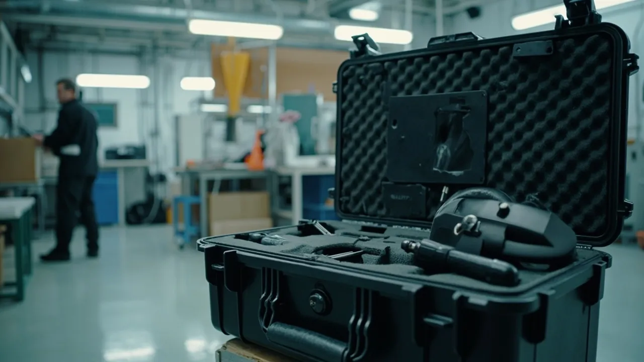
The job of a nut and bolt tooling case is to keep forming dies (hex dies, punch pins, head-forming dies, trimming dies), thread cutting tools (thread-rolling plates, taps, thread mills, round dies) and inspection gauges dimensionally accurate, edge-intact and free of mating-face damage through teardown, regrinding, inter-plant changeover and export shipment. The mechanical property class of a nut or bolt is set by material and heat treatment, whether 8.8, 10.9 or 12.9 under ISO 898-1 and its Chinese counterpart GB/T 3098.1, while the across-flats dimension, head form and thread accuracy depend entirely on the condition of the tooling. Thread fit tolerances follow systems such as ISO 965 and GB/T 197. If a carbide thread tool loses a corner in transit, the real cost is usually not the tool, it is the downtime on the whole line.
The management challenge with this tooling is that it is high-variety, low-volume, high-value and fast-moving. A nut shop's hex dies may cover a dozen sizes from M6 to M24, each with different heights and chamfer forms, while a bolt shop combines head-forming dies, trimming dies and thread plates. Tooling travels from the crib to the machine, back for regrinding, from the main plant to a sister plant, and from a domestic site to an overseas customer, with multiple manual transfers along the way. Every case opening is a chance to strike an edge. This article breaks protection down by component type and gives workable practice on case material, IP ratings under IEC 60529 and GB/T 4208, cushioning inserts, rust control, tooling control and transport validation with ISTA, GB/T 4857, ASTM D4169 and MIL-STD-810H test methods.
Table of Contents
- 1. The tooling system in nut and bolt production and its protection needs
- 2. Nut forming dies: bore accuracy of hex dies and punch pins
- 3. Bolt head-forming dies and trimming dies
- 4. Thread cutting tools: plates, taps, thread mills and round dies
- 5. Tool materials and cutting edges: carbide, high-speed steel and coatings
- 6. Punch pins and ejector rods: straightness protection for slender parts
- 7. Die holders, die sleeves and backing blocks: mating faces and heavy loads
- 8. Inspection gauges: thread ring gauges, plug gauges and sorting machine parts
- 9. Case structure, hardware and tooling control
- 10. Sealing and ingress protection: IP65/IP67 under IEC 60529 and GB/T 4208
- 11. Insert design and transport validation: EVA/PE, ISTA, GB/T 4857, ASTM D4169
- 12. Rust control, selection table and OEM/ODM procurement acceptance
- Frequently Asked Questions
- Conclusion & Related Reading
1. The tooling system in nut and bolt production and its protection needs
Nuts and bolts are both fasteners, but their forming tooling differs markedly:
- Nut route. Hex geometry and the bore are formed by cold heading or hot forging. Core tooling includes the hex die with its insert, the punch pin, chamfer dies and tapping tooling. Some products follow a hot-forge plus machining route, which brings in turning tools and thread cutting tools.
- Bolt route. Head and shank are formed by multi-station cold heading. Core tooling includes the shear knife, first punch, head-forming punch, reducing die and trimming die. Threads are produced by thread rolling, with thread-rolling plates and rolling dies as the core tooling.
- Shared stages. Inspection gauges (thread ring gauges, plug gauges, calipers, vision measuring machines), die holders and backing blocks, and hydraulic and pneumatic components.
Classifying this tooling by failure mode is more useful than classifying by name:
| Component class | Typical parts | Dominant failure mode | Protection focus |
|---|---|---|---|
| --- | --- | --- | --- |
| Forming dies | Hex die, insert, head-forming die, reducing die | Forming-face scoring, bore dimensional drift, insert corner chipping | One part per pocket, bore locating, working face suspended, rust control |
| Punch pins and rods | Punch pin, piercing pin, ejector rod, stripper rod | Bending, end chipping, straightness loss | Continuous channel, full-length support, end caps |
| Shearing dies | Shear knife, trimming die, cut-off blade | Thin-edge chipping, flatness deviation | Edge up, full-face backing block, never stacked |
| Thread cutting tools | Thread-rolling plate, tap, thread mill, round die, rolling die | Crest collapse, edge chipping, coating damage | Tooth-face and edge isolation, individual sleeve, rust-inhibiting paper |
| Gauges | Thread ring gauge, plug gauge, caliper, gauge block | Working-face wear, dimensional drift, corrosion | One part per pocket, soft liner, rust and magnetism control |
| Die holders and heavy parts | Die sleeve, die holder, backing block, clamp plate | Mating-face damage, distortion under load | Full-face support, hard separation, reinforced base |
The first three classes plus thread cutting tools are the core tooling where precision is value. A coated carbide thread tool has cutting edge geometry designed for a specific workpiece material, and once the edge chips or the coating is scratched, cutting force and thread surface quality change immediately. This tooling follows three rules: individual locating, no contact between working faces and any hard object, and no load on cutting edges or forming faces.
Gauges and heavy parts have their own priorities. Gauges suffer accuracy drift and corrosion, and because they are metrology-controlled items, impact means recalibration. Heavy parts suffer mating-face damage and case loading, and once a die sleeve mating face carries a burr, coaxiality error appears on assembly.
JUNZHJIA's usual approach in the fastener tooling sector is tiered, split-case packaging based on the customer's tooling list: forming dies and thread cutting tools in dedicated compartmentalized cases with individual sleeves, thin-edge shearing parts in a dedicated thin-edge case, gauges in a more formal instrument case with one pocket per item and a checklist, and heavy die holders in a case with a reinforced base. Total packaging cost stays under control while the most expensive tooling sits on the most controlled path.
2. Nut forming dies: bore accuracy of hex dies and punch pins
Nut forming centers on the fit between the hex die and the punch pin. The die cavity sets the across-flats dimension and hex form, while the punch pin sets the bore size and wall quality.
Their failure modes differ clearly:
- Hex die. Forming-cavity scoring and corner wear. The corners of a hex cavity are stress concentration zones, so a ding in transit produces underfilled or rounded corners on the finished nut. Insert-type hex dies, often carbide or high-alloy die steel, are brittle and chip easily on edge impact.
- Punch pin. Bending and end chipping. A punch pin is a slender part, sometimes 100 to 300 mm long, and it bends under transport vibration if both ends are unsupported. Its piercing end is a working face that handles uniform compressive stress but not a point load from a drop.
For hex dies, three measures apply:
- Locate on the outside diameter, suspend the cavity. Support the die on its outside diameter or locating face so the cavity touches nothing hard.
- One per pocket, never stacked. Insert-type hex dies must each have their own pocket, because stacking on one layer transfers the upper part's weight through the corners into the lower part's cavity corners.
- Corner protection. For dies with carbide inserts, add soft corner protectors. The cost is minimal and the reduction in corner chipping is substantial.
For punch pins, the logic matches any slender part: continuous channel, full-length support, end caps. Match the channel diameter to the pin with 0.1 to 0.2 mm single-side clearance so the foam provides the support, and cap the piercing end so it cannot strike the case wall and burr. For pins longer than 300 mm, add a mid-length support block to avoid the sag that comes from end support only.
3. Bolt head-forming dies and trimming dies
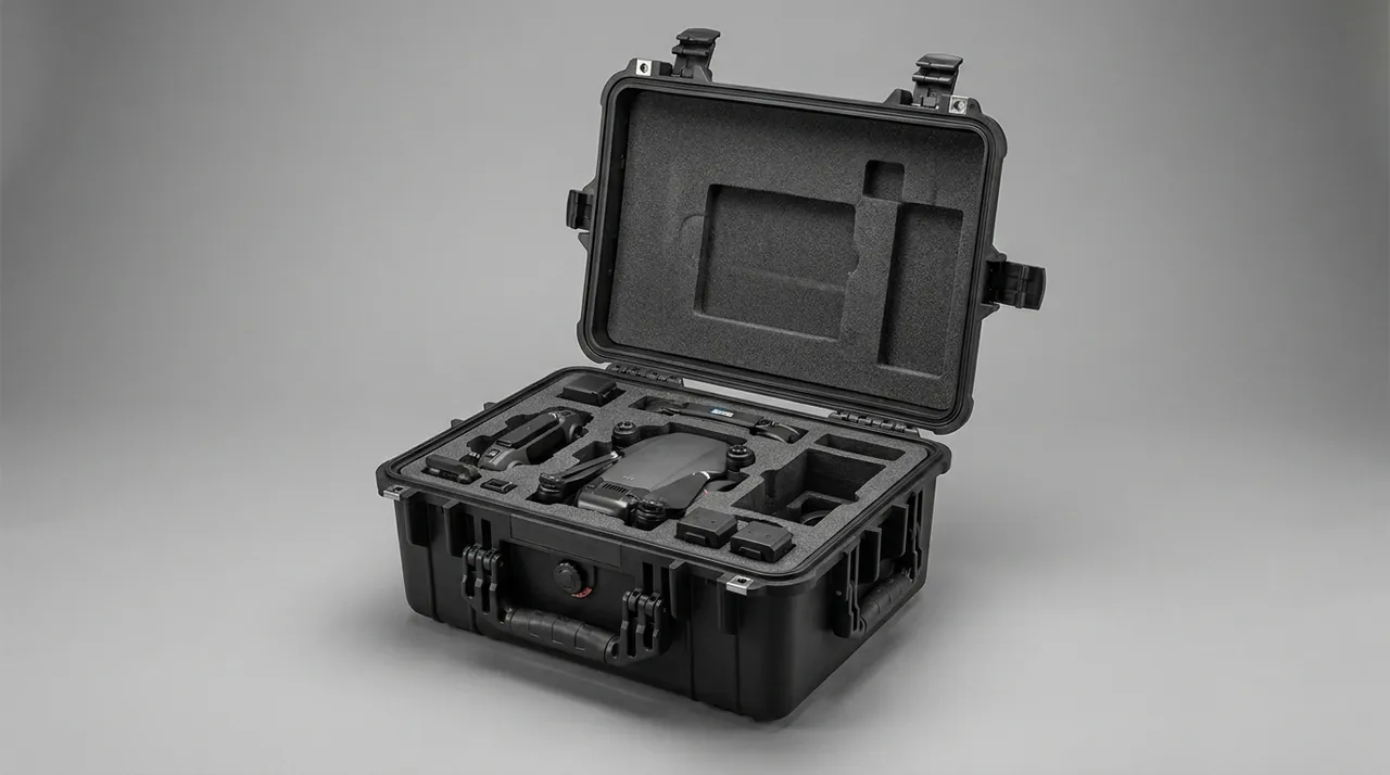
Bolt head forming relies on multi-station punches: the first punch pre-forms, the forming punch sets the head shape, the finishing punch refines it, and the final station trims the hex or flange profile with a trimming die. This tooling behaves much like a cold-heading die set, but the detail that matters most is the accuracy of the head-forming contour.
- A head-forming punch face is often curved or complex, so a localized ding shows up directly in the flatness of the bolt's bearing face and in head height. Bearing-face flatness is one of the key parameters behind consistent preload after assembly.
- A trimming die edge is a thin-edge structure that fails mainly by chipping, and trimming dies are usually used in pairs or sets, so loose packing leads directly to mutual impact.
Packing recommendations:
| Tooling | Main risk | Packing approach |
|---|---|---|
| --- | --- | --- |
| First punch / forming punch | Forming-face dents, contour distortion | One per pocket, forming face up, soft transition layer |
| Finishing punch | End-face flatness deviation | Full-face end support, high-density backing block |
| Trimming die | Edge chipping | Edge up, full-face support, one per pocket |
| Reducing die | Bore scoring | Bore locating, working face suspended |
| Shear knife | Chipping, edge rolling | Edge protector, full-face support |
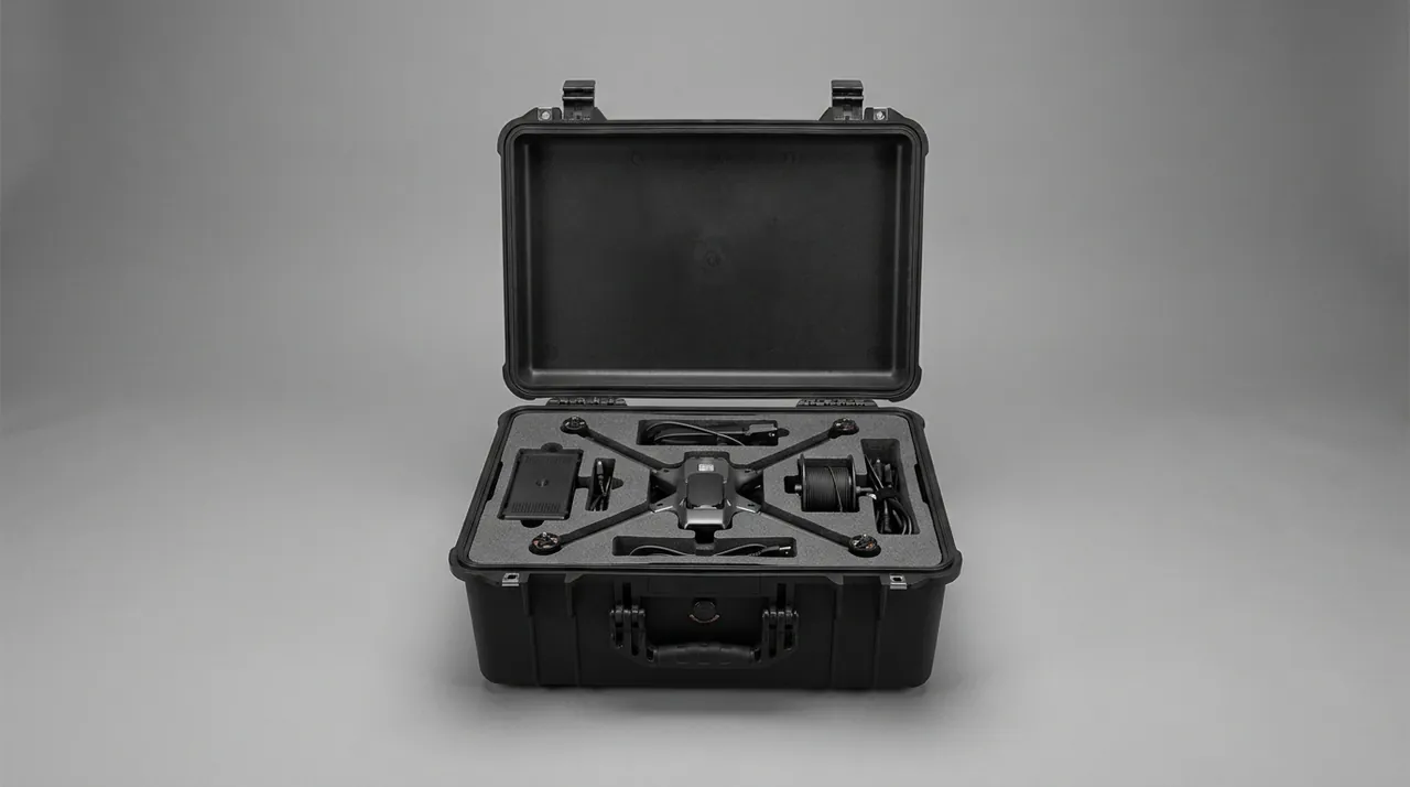
For multi-station bolt tooling, the matched-set case concept works well: one case maps to one die set, each station has a numbered pocket, and the shop changes the whole set at once. That prevents the mix-and-match situation that arises when a single station goes missing, and it makes tool-life tracking much easier.
4. Thread cutting tools: plates, taps, thread mills and round dies
Thread cutting tools are the category most often scrapped because of poor packaging, and the reason is that their value is concentrated in an extremely narrow contact surface: the crest of a thread-rolling plate, the margin of a tap, the cutting edge of a thread mill, the chamfer of a round die.
| Tool | Dominant failure mode | Packing essentials |
|---|---|---|
| --- | --- | --- |
| Thread-rolling plate | Crest collapse, pitch deformation | Teeth up, layer dividers, matched pairs numbered, rust-inhibiting paper |
| Tap | Bending, edge chipping | Longitudinal channel foam, both ends supported, spacing 10 mm or more |
| Thread mill | Edge chipping, coating damage | Individual sleeve, edges touching nothing, own compartment |
| Round die | Edge chipping, OD damage | One per pocket, soft end pads |
| Rolling die | Bore damage, tooth-face scratching | Bore locating arbor, tooth form suspended, compartmentalized tray |
Thread mills and coated tools deserve a specific note: a coating such as TiN, TiAlN or DLC is a micron-scale film, and any rubbing causes localized spalling. A spalled area becomes a stress concentration point and a built-up edge initiation site during cutting. Coated tools therefore must not rub directly against firm foam; use a soft sleeve such as an elastomer or non-woven cover, or a suspended fixture.
The plate management logic from thread-rolling equipment applies here too: pack, ship and issue plates in matched pairs with numbering, so the tooth-form mismatch caused by mixing pairs never happens. Thread accuracy itself is governed by tolerance systems such as ISO 965 and GB/T 197, and because tool accuracy management is part of the quality system, the packaging plan should be linked to the accuracy ledger.
5. Tool materials and cutting edges: carbide, high-speed steel and coatings
Tool material directly determines packaging strategy. Three common classes:
- High-speed steel (HSS, cobalt HSS). Relatively tough and more impact resistant than carbide, but lower hardness at HRC 62 to 67. In transit the risks are edge chipping and bending, and the material is less sensitive to foam hardness.
- Carbide (tungsten carbide). High hardness at HRA 89 to 93 and excellent wear resistance, but low transverse rupture strength and high brittleness. The dominant transit risk is corner chipping from a point load, so the edge must be suspended, load must be carried by non-working faces, and carbide parts must not touch each other, because two carbide bodies striking each other typically chip both.
- Coated tools. The substrate may be HSS or carbide, with a micron-scale coating. Beyond substrate risk, coating spalling and scratching must be prevented.
A practical material rule is this: do not let like materials strike each other, and never put two carbide parts in the same pocket. The ideal arrangement for carbide is an individual sleeve plus compartments, with at least 10 mm of cushioning separation between compartments.
One further point: the transition between a tool's shank and its cutting portion is a stress concentration zone and should not carry load in transit. When designing the insert, place support points on the cylindrical shank or a non-functional surface, never on the transition region near the cutting edge.
6. Punch pins and ejector rods: straightness protection for slender parts
Punch pins and ejector rods are the most common slender parts in a nut and bolt shop, typically 100 to 400 mm long and 5 to 30 mm in diameter. Their failure mode is unambiguous: bending and end chipping.
Bending comes from accumulated vibration rather than a single impact. Workable measures:
- Three or more support points. Place supports at roughly one-fifth, one-half and four-fifths of the length with soft support between, so the middle does not sag as it would with end support only.
- Continuous channels rather than intermittent pockets. Intermittent pockets leave the pin spanning between openings, creating localized high stress; a continuous channel lets the foam support the full length.
- Axial restraint. Fit elastic stops at both ends so the part can cushion slightly but cannot run. A part that runs strikes the case wall repeatedly and burrs its end face.
- End protection. Cap or pad the piercing end and the ejection end.
For pins shipped in sets, such as a die set with five to ten pins of different lengths, use stepped channels with position markings so each length has its own place. Mixed loading not only slows retrieval, it lets short pins move around inside long channels, increasing the chance of damage.
| Slender part | Typical size | Main risk | Packing essentials |
|---|---|---|---|
| --- | --- | --- | --- |
| Punch pin | 5 to 30 mm dia., 100 to 300 mm long | Bending, end chipping | Continuous channel, three-point support, end cap |
| Ejector / stripper rod | 4 to 20 mm dia., 80 to 250 mm long | Bending, thread end damage | Full-length support, thread protector |
| Feed rod | 6 to 25 mm dia., 150 to 400 mm long | Sagging and bending | Mid support block, axial restraint |
| Tie rod / linkage | Irregular long part | Bending, mating-face damage | Three-point support, end caps |
| Long mandrel | 8 to 40 mm dia., 200 to 600 mm long | Straightness loss | Long-item case, full-length support |
7. Die holders, die sleeves and backing blocks: mating faces and heavy loads
Die holders, die sleeves, backing blocks and clamp plates are heavy-load, mating-face components. Their value is not the highest precision class but the fact that once a mating face is damaged, coaxiality across the whole assembly chain becomes hard to guarantee.
Take a die sleeve. The fit between its bore and a die's outside diameter is usually a transition or small-clearance fit. A burr or dent on that mating face causes eccentricity on assembly, which shows up as poor coaxiality between the hex form and the bore on a nut, or between head and shank on a bolt. This deviation is hard to spot in the finished part but affects assembly performance significantly.
Protection essentials:
- Suspend the mating face or support it fully. A mating face must not carry a point load; transfer load through non-mating surfaces such as end faces or the mid-section of the outside diameter.
- Hard separation, never stacked. Heavy parts are never stacked. Put solid dividers or wooden battens between layers so the upper weight never reaches a lower mating face.
- Reinforced base structure. Heavy cases need a ribbed or full tray-style base, with stacking strength designed at roughly 1.5 times total case weight as a safety factor. Following the GB/T 4857 series logic, a stacking test should replicate the actual layer count and dwell period.
- Lifting clearance. Where the shop crane-lifts a part and lowers it directly into the case, provide lifting lugs or clearance for the sling so the strap does not crush the lid.
8. Inspection gauges: thread ring gauges, plug gauges and sorting machine parts
Gauge protection follows different logic, because a gauge is a metrology-controlled item whose value lies in traceability. Once impact causes dimensional drift, recalibration is mandatory, and recalibration means downtime and extra cost.
Thread ring gauges and plug gauges fail through working-face wear and localized impact damage. A thread ring gauge's go and no-go thread form determines whether an inspection result is valid at all, so the packing must:
- Give each gauge its own pocket with the working face touching nothing hard.
- Control rust, since thread gauges are usually alloy tool steel or carbide and corrosion changes the pitch diameter directly.
- Control magnetism and thermal shock, since high-precision gauges are temperature sensitive and should not share a case with heat sources or strong magnetic fields.
- Include a checklist and pocket map, so every item has a place and a missing item is visible, which prevents the careless placement that causes impact.
Gauge blocks and calibration weights must satisfy metrology management requirements, and packing must prevent impact and mutual rubbing. Vision measuring machine lenses, light sources and sensors are precision electronic items and need independent cushioned compartments with dust caps. For gauge cases containing static-sensitive components, an anti-static insert may be appropriate; see instrument case selection guide for options.
9. Case structure, hardware and tooling control
On case material, tooling cases in fastener shops are usually chosen from copolymer polypropylene, high-density polyethylene, ABS and modified engineering plastics:
| Material | Impact | Low-temp toughness | Oil resistance | Typical use |
|---|---|---|---|---|
| --- | --- | --- | --- | --- |
| Copolymer PP | Good | Fair to good | Moderate | General tooling cases, best value |
| HDPE | Very good | Very good | Fair to good | Heavy-duty cases, die holder cases |
| ABS | Moderate | Moderate | Fair | Gauge cases, appearance-driven cases |
| Modified PP / PA | Good | Good | Good | Oil resistance, anti-static, flame retardant |
The oil resistance column matters especially in a fastener shop, where cold-forming oil, cutting fluid and hydraulic oil are everyday realities. Prolonged contact makes some materials swell or stress-crack. Where cases routinely hold oily tooling, prefer a more oil-resistant material or add oil-absorbent padding.
For export to the EU or North America, customers often specify a material flammability rating. UL94 is the common basis for evaluating plastic material flammability, with HB for horizontal burning and V-0, V-1 and V-2 for vertical burning, lower numbers being more demanding. It must be stated that UL94 rates the material, not the finished case; a flammability claim about a finished case requires separate evaluation of the finished structure.
For mechanical impact, the IK rating defined in IEC 62262 (IK00 to IK10) characterizes impact resistance in energy terms. Tooling cases are commonly designed around the IK08 (5 J) level, while heavy die holder cases or long-haul export cases may call for IK10 (20 J). IK performance depends strongly on wall thickness, rib layout and corner radius, and well-placed ribs are usually more economical than extra wall thickness.
Tooling control is a frequent requirement in fastener shops. Carbide tools and thread gauges are high in value, small in size and easy to lose, so cases often need locks or tamper seals. For lock scheme selection across control levels, see case lock customization options, and for hardware matching see matching case hinges, latches and seals. Build a ledger per case at the same time: one case maps to one tooling set and one location drawing, with counts reconciled on issue and return. That protects the tooling and builds the life data.
10. Sealing and ingress protection: IP65/IP67 under IEC 60529 and GB/T 4208
IP codes are the most basic and most misread specification on a protective case. IEC 60529, and GB/T 4208 which China adopted equivalently, define the first characteristic digit as protection against solid foreign objects and dust, and the second as protection against water.
| IP code | Dust | Water | Typical fastener shop scenario |
|---|---|---|---|
| --- | --- | --- | --- |
| IP54 | Dust protected (limited ingress) | Splash resistant | Short in-plant circulation |
| IP65 | Dust tight | Jet water resistant | Brief outdoor transfer, washdown areas |
| IP66 | Dust tight | Powerful jet resistant | Loading in rain, short port drayage |
| IP67 | Dust tight | Temporary immersion (order of 1 m / 30 min) | Sea freight, container condensation, rainy-season warehousing |
| IP68 | Dust tight | Continuous immersion (per manufacturer conditions) | Specialized water transport |
For die and tooling cases, IP67 is the usual threshold for export sea freight and high-humidity warehousing in southern China. Day-night temperature swings inside a container deposit water vapor as liquid on the case surface, and only a temporary-immersion-rated seal keeps it out. Once carbide tools and thread gauges take on water, corrosion changes their dimensions, and that change is often not apparent before calibration. IP65 suits in-plant and short-distance use, and IP66 fits outdoor loading and short port drayage.
For sealing details, see the sealing structure of IP67 protective cases. The conclusion here is short: gasket compression should be held between 25 and 35 percent. Below 20 percent leaks are likely, and above 40 percent the gasket takes a permanent set and the case becomes hard to close. On tooling cases opened many times per shift, this matters a great deal.
The better the seal, the more pronounced the pressure problem becomes. During air freight or thermal cycling, the pressure difference can make a lid very hard to open or locally suck the gasket out of shape, so long-haul tooling cases should be specified with a pressure equalization valve. Gauge cases travelling by air should also be designed so parts remain easy to remove immediately after opening.
11. Insert design and transport validation: EVA/PE, ISTA, GB/T 4857, ASTM D4169
The insert is the real protective gear of a tooling case. Material properties are as follows:
| Material | Density range (kg/m3) | Resilience | Abrasion resistance | Best suited to |
|---|---|---|---|---|
| --- | --- | --- | --- | --- |
| EVA | 60 to 120 | Good | Good | Tooling compartments, frequent access |
| Cross-linked PE foam | 25 to 60 | Fair | Fair | General cushioning, large-area support |
| PU foam | 20 to 45 | Good | Moderate | Gauges, precision instruments |
| EPE | 18 to 30 | Fair | Poor | Low-cost void fill, transition layer |
| XPE | 30 to 60 | Fair | Good | Water barrier layers, pads |
Tooling cases most often use an EVA inner locating layer plus cross-linked PE foam for energy absorption. For carbide tools and gauges, use a two-layer approach of individual sleeve plus machined pocket; for punch pins and rods, use continuous channels; for hex dies and die sleeves, locate on the outside diameter with the cavity or bore suspended.
Pocket tolerance depends on the process: hot-knife cutting lands around plus or minus 0.5 mm, CNC routing reaches plus or minus 0.2 mm, and die cutting suits high-volume thin sheets. Tier A tooling should be CNC routed with 0.3 to 0.5 mm single-side clearance. For fuller comparisons, see foam material comparison, the EVA insert customization process and the general method in the custom foam insert selection guide.
Three transport validation frameworks are commonly used:
- ISTA. ISTA 3A covers single packages up to 70 kg in parcel and LTL service with drop, random vibration and concentrated impact. ISTA 3E covers unitized loads with compression, vibration and inclined impact. ISTA 2A suits basic single-case verification.
- GB/T 4857 series. China's basic test methods for transport packages, covering vibration, impact, stacking, drop and compression, and the series most cited by domestic customers.
- ASTM D4169. Organizes test intensity around distribution cycles, well suited to North American customers and complex logistics chains.
In addition, methods 514 (vibration) and 516 (shock) of MIL-STD-810H are frequently cited as the methodological basis for environmental testing. This must be stated plainly: citing MIL-STD-810H means only that its test methods are used. It does not mean the product holds any military certification or qualification. See MIL-STD-810H compliance notes, ISTA transport testing procedures and GB/T 4857 transport packaging tests.
| Framework | Primary scope | Common sub-tests | Suggested use |
|---|---|---|---|
| --- | --- | --- | --- |
| ISTA 3A | Parcel and LTL single package | Drop, random vibration, concentrated impact | Export express, single-case dispatch |
| ISTA 3E | Unitized load | Compression, vibration, inclined impact | Pallet dispatch, third-party warehousing |
| GB/T 4857 | Domestic transport packaging | Vibration, stacking, drop, compression | Domestic customer acceptance |
| ASTM D4169 | Distribution cycle | Sequences assembled per DC | North America, complex logistics chains |
The practical advice is to copy your actual logistics chain into the test conditions rather than copying a good-looking report. Draw the node map from dispatch to machine installation, mark the maximum drop height, longest vibration duration and highest stack count, and then choose the program.
12. Rust control, selection table and OEM/ODM procurement acceptance
Corrosion of a metal part requires three conditions at once: a metal surface, water, and oxygen with an electrolyte. A protective case controls the water, using sealing and dehumidification to hold internal relative humidity below the critical value for corrosion, commonly taken as about 60 percent RH for carbon steel.
A three-layer system is well established for tool and gauge transport:
- Contact layer. Rust-inhibiting paper or film wrapped around the tooling. VCI-bearing products sublimate vapor-phase corrosion inhibitor inside the enclosed space, where it adsorbs onto the metal surface as a molecular film.
- Barrier layer. A VCI film or aluminum-plastic laminate envelope reduces the water vapor transmission rate.
- Moisture absorption layer. Desiccant in the case plus a two-stage humidity indicator card, typically 40 percent RH and 60 percent RH.
One caution is essential: VCI is not a substitute for process rust-preventive oil. VCI depends on an enclosed environment at reasonably stable temperature, and when a case is opened frequently or left open the concentration cannot be maintained. High-frequency in-plant tooling cases fit a thin oil film plus rust-inhibiting paper; long-term storage and export sea freight fit a VCI envelope plus desiccant. Desiccant quantity can be estimated from free internal volume at roughly 200 to 500 g of high-efficiency desiccant per 100 L, taking the upper end for long sea voyages. On carbide tools and thread gauges, working edges and faces corrode first, so they deserve the most attention before packing, and powder-free nitrile gloves prevent sweat from starting a corrosion pit.
On selection, the most common error is choosing a case from the largest component's footprint. The right order is to calculate load and stacking first, then fix external size and structure, and finally lay out the insert compartments:
- Total case weight W = sum of component net weights + insert weight + case self weight
- Required stacking strength F = W x stacked layers x safety factor (1.5 to 2.0 recommended)
- Internal clear size = largest component envelope + insert wall (15 to 25 mm per side) + finger-access allowance
- Keep total case weight in the 25 to 35 kg band; above 40 kg add casters, a telescopic handle or forklift pockets
Where a customer needs a dedicated case platform rather than a standard modular body, tooling and amortization come into play; see custom case mold cost analysis for the volume decision. In most cases, a standard modular case body combined with a custom insert lowers both the entry threshold and total cost considerably.
For acceptance, sampling is better than either full inspection or no inspection. The counting-sampling logic of GB/T 2828.1 offers a workable scheme: a tighter AQL for critical characteristics such as sealing, hardware and lock function, and insert pocket and layer accuracy, and a looser AQL for color variation and printing. See custom case acceptance AQL sampling for details.
On delivery capability, JUNZHJIA is manufactured by Kexin New Materials (Guangdong) Co., Ltd. and serves wholesale, distribution, OEM/ODM and global supply. We build foam inserts and compartment layouts to a customer's tooling list, match seals and hardware to the case platform, and can supply material and test documentation for a quality department to file. For nut and bolt tooling users we generally recommend prototyping with one die set plus one thread tool, validated through the real logistics chain before committing to volume; see how to choose a protective case OEM factory for factory evaluation criteria.
Frequently Asked Questions
Q: How should I select a die and tooling case for a nut and bolt shop, and which parameter should be fixed first?
A: The first parameters are the precision class, material and set size of the tooling, not the case size or IP rating. Tooling cases fail almost entirely through relative movement and mutual impact rather than water ingress. Select in this order. List the tooling with precision class, material (high-speed steel, carbide or coated), individual weight and items per set. Determine the longest item, since that normally sets the case length. Then design the insert: individual machined pockets with the forming cavity suspended for forming dies, continuous channels with three-point support for punch pins, individual sleeves plus machined pockets for carbide tools and gauges, and teeth-up plates with dividers for thread-rolling plates. Then choose cushioning, where heavy items above 20 kg do best with an EVA inner layer plus cross-linked PE outer layer. Only then choose the IP rating: IP67 under IEC 60529 and GB/T 4208 for export sea freight, IP65 for in-plant circulation. If the shop requires tooling control, confirm the lock or tamper seal scheme at the selection stage.
Q: What is the biggest transport risk for carbide tools, and what special packaging is required?
A: The biggest risk is corner chipping from a point load, followed by coating spalling. Carbide has high hardness at HRA 89 to 93 and excellent wear resistance, but low transverse rupture strength and high brittleness. It handles the uniform compressive stress of cutting but not a concentrated point load from a drop or mutual impact. Three requirements follow. First, the edge must be suspended, with load carried by a non-working surface such as the tool body base or shank; never let the edge face down against the insert or case floor. Second, do not let like materials strike each other, and especially never put two carbide parts in the same pocket, because two carbide bodies striking each other typically chip both. Use individual sleeves and compartments with at least 10 mm of cushioning separation between them. Third, prevent coating spalling: a coating such as TiN, TiAlN or DLC is a micron-scale film, and any rubbing causes localized spalling that becomes a stress concentration point and a built-up edge site during cutting, so coated tools must not rub against firm foam and should use elastomer or non-woven sleeves or a suspended fixture. Also note that the shank-to-cutting-portion transition is a stress concentration zone and should never carry load.
Q: How do I keep slender parts such as punch pins and ejector rods from bending in transit?
A: Support point placement and axial restraint matter more than foam thickness. First, support points: the dominant risk for a slender part is accumulated bending from vibration, not a single impact, so use three or more supports at roughly one-fifth, one-half and four-fifths of the length with soft support between, avoiding the sag that comes from end support only. Second, channel form: use continuous channels rather than intermittent pockets, because intermittent pockets leave the pin spanning between openings where stress concentrates, while a continuous channel lets the foam support the full length; match channel diameter to the pin with 0.1 to 0.2 mm single-side clearance. Third, axial restraint: fit elastic stops at both ends so the part can cushion slightly but cannot run, because a running part strikes the case wall repeatedly and burrs its end face. Fourth, end protection: cap or pad the piercing end and the ejection end, and add a mid support block for pins longer than 300 mm. For pins shipped in sets, use stepped channels with position markings so lengths do not mix; mixed loading slows retrieval and lets short pins move around inside long channels, increasing the chance of damage.
Q: What special requirements apply to gauges such as thread ring gauges and plug gauges?
A: Gauge protection follows different logic, because a gauge is a metrology-controlled item whose value lies in traceability. Once impact causes dimensional drift, recalibration is mandatory and means downtime plus added cost. Four requirements follow. First, give each gauge its own pocket with the working face touching nothing hard, since a thread ring gauge's go and no-go thread form determines whether an inspection result is valid at all. Second, control rust: thread gauges are usually alloy tool steel or carbide, corrosion changes the pitch diameter directly, so wrap in rust-inhibiting paper or VCI film and include desiccant. Third, control magnetism and thermal shock: high-precision gauges are temperature sensitive and should not share a case with heat sources or strong magnetic fields. Fourth, include a checklist and pocket map so every item has a place and a missing item is visible, which prevents careless placement and impact. Gauge blocks and calibration weights must satisfy metrology management requirements with packing that prevents impact and mutual rubbing, and vision measuring lenses, light sources and sensors are precision electronic items needing independent cushioned compartments with dust caps; anti-static insert options apply where static-sensitive components are present.
Q: How should heavy mating-face parts such as die holders and die sleeves be packed?
A: Their value is not the highest precision class but the fact that once a mating face is damaged, coaxiality across the assembly chain is hard to guarantee. Four points. First, suspend or fully support the mating face, since it must not carry a point load; transfer load through non-mating surfaces such as end faces or the mid-section of the outside diameter, because the fit between a die sleeve bore and a die's outside diameter is usually a transition or small-clearance fit, and a burr or dent on that face causes eccentricity after assembly that shows up as poor coaxiality between the hex form and bore on a nut. Second, hard separation and no stacking, with solid dividers or wooden battens between layers so upper weight never reaches a lower mating face. Third, a reinforced base structure with ribs or a full tray-style base, designed at roughly 1.5 times total case weight as a safety factor and validated by stacking tests that replicate the actual layer count and dwell period following the GB/T 4857 series logic. Fourth, lifting clearance: where a crane lowers a part directly into the case, provide lifting lugs or clearance for the sling so the strap does not crush the lid.
Q: For export sea freight on die and tooling cases, how do I choose between IP65 and IP67?
A: Choose from the harshest link in the logistics chain. IP65 means dust tight plus protection against water jets, covering in-plant circulation, brief outdoor transfer and washdown areas, and it is entirely sufficient for day-to-day internal movement. IP67 means dust tight plus protection against temporary immersion, in the order of one meter for 30 minutes, and its real value lies in container condensation: day-night temperature swings inside a sea freight container deposit water vapor as liquid on the case surface, and only a temporary-immersion-rated seal blocks it. Once carbide tools and thread gauges take on water, corrosion changes their dimensions, and that change is often not apparent before calibration. The decision rule is simple: will the case travel by sea, or enter a high-humidity warehouse during the rainy season? If yes, specify IP67; if no, IP65 is more economical, with IP66 fitting outdoor loading and short port drayage. Remember that an IP rating is a type test result and real protection depends on the gasket retaining compression, so hold compression between 25 and 35 percent and check hinge and latch clamping regularly. Fastener shops also run oily, so confirm gasket oil and aging resistance separately, and add a pressure equalization valve for air freight or thermal cycling.
Q: How should I handle rust prevention on tools and gauges, and what transport testing applies for export?
A: Use a contact layer, a barrier layer and a moisture absorption layer. For the contact layer, wrap the tooling in rust-inhibiting paper or film; VCI-bearing products sublimate vapor-phase corrosion inhibitor inside the enclosed space and adsorb onto metal as a molecular film. For the barrier layer, use a VCI film or aluminum-plastic laminate envelope to reduce the water vapor transmission rate. For the moisture absorption layer, place desiccant in the case with a two-stage humidity indicator card, typically 40 percent RH and 60 percent RH. Desiccant quantity can be estimated from free internal volume at roughly 200 to 500 g of high-efficiency desiccant per 100 L, taking the upper end for long sea voyages. Note that VCI is not a substitute for process rust-preventive oil, because it depends on an enclosed space and its concentration cannot be maintained if the case is opened frequently. For testing, draw the logistics chain node map first: ISTA 3A with drop, random vibration and concentrated impact for single-case LTL dispatch, ISTA 3E for pallet dispatch, the GB/T 4857 series for domestic acceptance, and ASTM D4169 distribution cycles for North American customers and complex chains. Where a customer specifies an environmental test methodology, methods 514 and 516 of MIL-STD-810H can be referenced, with the explicit note that this means only the test methods are adopted and implies no military certification. Samples must use production structure and process.
Q: How should tooling control and the acceptance flow be arranged for a die and tooling case?
A: Tooling control is a frequent requirement in fastener shops, because carbide tools and thread gauges are high in value, small in size and easy to lose. Control usually comes in three levels: a plain latch for internal circulation, a padlock or combination lock for multi-shift shared use, and a tamper seal or one-time seal for inter-plant and external customer delivery where it matters whether the case was opened. When selecting, confirm that the lock does not interfere with the seal, since a lock position that compromises gasket compression destroys the IP rating, and check hinge and latch matching at the same time. The acceptance flow has five stages: requirement clarification covering the tooling list, precision classes, materials, items per set, logistics chain, target IP rating and control level; concept and insert drawings; prototype, ideally using one die set plus one thread tool run through the real logistics chain; validation, selecting items from ISTA 3A or 3E, GB/T 4857 or ASTM D4169 according to the logistics chain; and volume production with outgoing inspection. For outgoing inspection, sampling is preferable, with a tighter AQL for critical characteristics such as sealing performance, hardware and lock function, and insert pocket and layer accuracy, and a looser AQL for color variation and printing, following the counting-sampling logic of GB/T 2828.1. JUNZHJIA is manufactured by Kexin New Materials (Guangdong) Co., Ltd., serving wholesale, distribution, OEM/ODM and global supply, with inserts built to a customer's tooling list and supporting technical documentation.
Conclusion & Related Reading
The value of a nut and bolt tooling case comes down to two outcomes: whether a tool survives more regrind cycles, and whether it can go straight onto the machine on arrival. Neither is achieved by making the case thicker. It comes from grading tooling correctly, designing how a forming face or cutting edge carries load, assembling a complete moisture and rust control system, and building tooling control into the structure itself. In an industry where precision is profit, packaging is an underrated link in the chain.
If you are building a protection program for hex dies, punch pins, thread cutting tools or thread gauges, start with a complete tooling list and a logistics chain map, and ask the supplier for the insert concept before discussing the case body. Most rework and damage problems can be eliminated at the concept stage.
Related Reading