

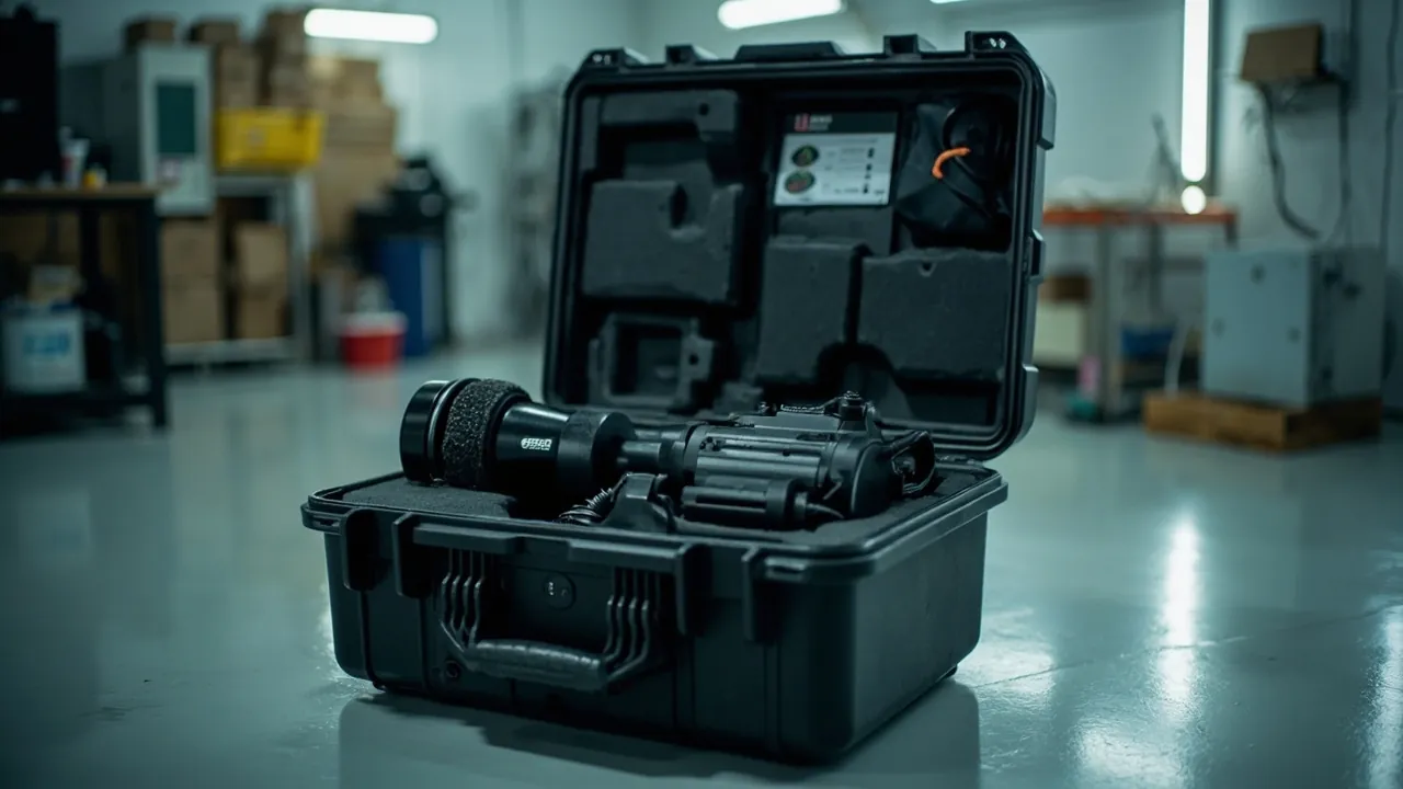
Two things sit at the heart of a hardware stamping shop: the die and the feeding mechanism. The conclusion first: press dies and feeder components combine precision edges, precision fits, and concentrated mass. They must be shipped in dedicated equipment cases with rigid locating, isolated compartments, and combined rust and moisture control. A wooden crate with loose fill produces a predictable set of failures on arrival: chipped edges, scored guide posts, bruised feeder rollers, and lost accuracy in servo feeders. The visible result is a die that will not dial in, an unstable feed pitch, and out-of-tolerance burrs. The value of a progressive die sits in the linked accuracy between edge clearance, guide post fit, and feed location. None of those three can be judged when the case is closed; all of them appear only after several hundred strokes on the press.
Hardware stamping is tightly coupled with cookware, tableware, and appliance hardware manufacturing. The same die may serve an in-house product and an external OEM order, so tools circulate frequently between plants, subcontractors, and brand owners. Every additional movement is a fresh exposure. This article is written for equipment engineering teams at stamping companies, tool and die shops, stamping automation integrators, die distributors, and OEM/ODM buyers. It covers component grading, case and insert design, edge and fit protection, precision protection for feeder components, rust prevention and cleanliness requirements, sealing and ingress protection levels, standard validation methods, and unpacking practice, and it explains how JUNZHJIA supports custom inserts and volume supply.
Table of Contents
- 1. Why Press Dies and Feeder Components Need a Dedicated Equipment Case
- 2. Component List and Sensitivity Grading
- 3. Failure Modes: Edge Chipping, Guide Post Damage, Roller Bruising and Servo Accuracy Loss
- 4. Weight Grading and Lifting Safety for Press Dies
- 5. Precision Protection for Feeder Components
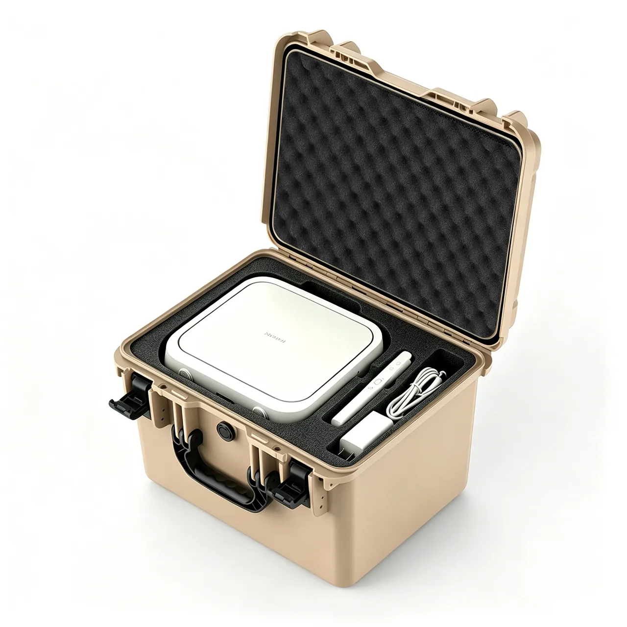
- 6. Size and Weight Boundaries: From 100 kg Single Dies to 5 t Progressive Dies
- 7. Case Structure and Material Selection
- 8. Insert and Locating Design: Separating Load Faces from Function Faces
- 9. Rust Prevention and Cleanliness: A VCI and ISO 4406 View
- 10. The Boundary of Press Safety Awareness
- 11. Sealing and Ingress Protection: An IEC 60529 and GB/T 4208 View
- 12. Transport Validation: GB/T 4857, ISTA and MIL-STD-810H
- 13. Labelling, Traceability and On-Site Unpacking
- 14. OEM/ODM Workflow, Acceptance and Reuse Management
- Frequently Asked Questions
- Conclusion & Related Reading
1. Why Press Dies and Feeder Components Need a Dedicated Equipment Case
The value distribution in stamping is unusual: it is not in the weight of the steel sheet but in clearances and fits measured in micrometres, and in the stability of a feed pitch measured in fractions of a millimetre.
First, die value is in edge clearance. Single-side clearance at blanking, piercing, trimming, and coining edges is designed as a percentage of material thickness. Once clearance changes through chipping, wear, or misalignment at assembly, the part immediately shows larger burrs, a wider fracture band, and dimensional drift. A chipped edge usually requires the whole edge to be reground, after which shut height and stripping clearance must be reset.
Second, die value is in guide post and bushing fit. Guide posts and bushings are the accuracy datum of the die, and their clearance directly sets the relative position of the upper and lower halves. Once the mating surface is scored or corroded, guiding accuracy drops, blanking clearance fluctuates through the stroke, and the part shows misalignment and off-centre punching.
Third, feeder value is in repeat positioning accuracy. The key metrics for NC, servo, and roller feeders are pitch accuracy and repeat positioning accuracy. Once a roller surface shows bruising or corrosion, feeding slips, pitch fluctuates, and the servo motor and encoder lose accuracy irreversibly after impact or moisture ingress.
Fourth, circulation frequency is high. A stamping shop holds many dies and changes them often, and dies circulate repeatedly between the plant, sister plants, and subcontractors. At twenty movements a year, a die may be handled nearly two hundred times over its life, and every event must be repeatable and verifiable.
Fifth, mass is concentrated. A press die has a far higher mass per unit volume than general equipment components, and a large progressive die can weigh several tonnes. Concentrated mass brings two consequences: very high stacking and support loads, and concentrated risk in lifting and handling.
Practical note: the most common hidden loss in a stamping shop is not the purchase price of a die but a die that will not dial in. Clearance out of tolerance, guide post seizure, and feed pitch drift frequently trace back to micro-chipping, guide post scoring, and roller bruising introduced in transport and storage, and diagnosing a progressive die feeding fault costs far more than a proper die case.
For stamping companies and die shops, the case also acts as an asset-management platform. One insert architecture can be shared across a product family, simplifying storage, circulation, and project kitting. Reuse assessment methods are described in protective case service life and reuse years.
2. Component List and Sensitivity Grading
Score each item on three axes - forming-precision sensitivity, shock fragility, and moisture and cleanliness sensitivity - to build the packing decision basis.
| Component | Typical material / structure | Critical sensitivity | Environment | Recommended protection |
|---|---|---|---|---|
| --- | --- | --- | --- | --- |
| Blanking or piercing die | Cr12MoV, SKD11, or carbide inserts | Cutting edge, insert joint faces | Chipping, rust | Edge location, protection strip, VCI |
| Punch | High-speed steel, powder metallurgy steel, carbide | Face edge, shank straightness, shoulder | Bending, chipping | Upright individual bores, shank support |
| Progressive die feed locators | Alloy steel, carbide | Locating pins, pilot pins, lift pins | Impact, rust | Compartment location, end face sleeves |
| Guide post and bushing | GCr15, bronze self-lubricating | Mating cylinder, perpendicularity | Scoring, rust | Paired fixing, anti-rust paper |
| Stripper plate and blank holder | Alloy steel, spring steel | Flatness, guide holes | Distortion, rust | Flat support, interleaving pads |
| Elastic elements (springs, polyurethane) | 65Mn, polyurethane | Preload height, fatigue life | Set, ageing | Stored free or lightly preloaded |
| Feeder roller and pinch roller | Alloy steel, polyurethane coated | Outer diameter, surface roughness, journals | Bruising, rust, coating ageing | Individual slots, outer diameter held clear |
| Servo feeder assembly | Servo motor plus gearbox plus encoder | Bearings, encoder, connectors | Impact, moisture, condensation | Whole-unit cushioned seat, separate cavity, desiccant |
| Feed rail and slider | Alloy steel, linear guide | Raceways, preload | Impact, rust, contamination | Horizontal fixing, end stops |
| Leveller roll stack | Alloy steel, chrome plated or polished | Roll surface roughness, parallelism | Bruising, rust | Compartments, roll surfaces held clear |
| Die set components (frame, support) | Cast iron, 45 steel | Mounting faces, T-slots | Rust, impact | Large flat support, moisture barrier below |
| Gauges and templates | Aluminium, tool steel | Measuring faces, datums | Distortion, scoring | Dedicated case, datum faces held clear |
| Control and sensors | Plastic or metal housings | Connectors, sealing faces | Moisture, dust, vibration | Separate compartment, ESD packaging |
The pattern is clear: edge components and guide posts are the physical and fit-accuracy priority, feeder rollers and servo mechanisms are the precision and electrical priority, and gauges and controls are the slow-failure items that are most often overlooked.
3. Failure Modes: Edge Chipping, Guide Post Damage, Roller Bruising and Servo Accuracy Loss
Edge chipping. The blanking edge is the hardest and least ductile region of the die. When the die is struck laterally, or when an edge contacts another hard component, small chips form. A chip may be a fraction of a millimetre, yet it immediately shows up as out-of-tolerance burrs and a wider fracture band, and it propagates over subsequent strokes. In a progressive die, adjacent stations often share a plate, so a single chip affects the whole process chain.
Guide post and bushing scoring and corrosion. The guide mating surface is the accuracy datum of the die. Scoring or corrosion destroys guiding accuracy, the blanking clearance fluctuates through the stroke, and the part shows misalignment and off-centre punching. On ball-bearing guide posts, scoring also produces ball indentations and seizure. On bronze self-lubricating bushings, sulphur and chlorine contamination causes discolouration and loss of lustre.
Insert joint face damage. Segmented die inserts are located by mating faces and fasteners. Transport vibration loosens fasteners slightly, the insert shifts, and after assembly the contour is offset and dimensions drift.
Feeder roller bruising. The roller outer diameter is the working surface that contacts the material. Once it shows bruising, impact damage, or local rust spots, feeding slips cyclically and pitch fluctuates. Chrome plated and polyurethane coated roll surfaces are especially vulnerable to impact and oil contamination.
Servo feeder accuracy loss. A feeder assembly built from a servo motor, gearbox, and encoder is highly sensitive to shock and vibration. Impact indentations in bearings cause the unit to run hot and fail quickly. Impact to the encoder causes signal fluctuation or outright damage. Connectors loosen under vibration and produce intermittent faults.
Leveller roll surface damage. Roll surface roughness and parallelism together determine sheet flatness. Impact damage leaves a local bruise, and the flattened sheet retains a matching trace.
Electrical moisture and condensation. Electrical components in NC feeders and servo systems dislike moisture, condensation, and dust. On cross-climate transport, temperature swings create condensation inside electrical components, lowering insulation resistance and corroding terminals.
Safety note: dies and feeder mechanisms are a combination of heavy and precision components, so lifting and handling must use dedicated lifting gear or symmetrical load points. Never pass a wire rope through a die cavity, a guide post bore, or a stripper screw hole to lift a die; edge chipping and guide post scoring usually happen at exactly this step. Stamping operations must follow the plant's established safeguarding, lockout-tagout, energy isolation, and lifting permit procedures. A case is one element of that system and cannot replace any safeguarding device or management measure.
4. Weight Grading and Lifting Safety for Press Dies
Press die weight spans an enormous range, from 100 kg for a small single-station die to several tonnes for a large progressive die. Each weight class needs its own packing, support, and lifting route.
| Weight band | Typical die | Packing approach | Insert strategy | Handling |
|---|---|---|---|---|
| --- | --- | --- | --- | --- |
| Under 200 kg | Single-station piercing die, small blanking die | Wheeled hard case | Fully conformal cut insert | Two-person lift or pallet truck |
| 200 - 800 kg | Medium blanking die, compound die | Case with pallet base | Rigid base support plus lateral restraint | Forklift or pallet truck |
| 800 - 2000 kg | Multi-station die, medium progressive die | Case plus integrated pallet structure | Four or more distributed supports, top clamping | Forklift, verify pallet dynamic rating |
| 2000 - 5000 kg | Large progressive die, automated line tooling | Heavy case or box pallet | Steel skeleton plus replaceable foam layers | Overhead crane with dedicated gear |
| Over 5000 kg | Full line tooling set | Ship as individual components, assemble on site | Per-component protection | Follow the lift plan |
Lifting and handling safety points.
- Lifting points must be on the die body, never on the case. The case provides protection only and is not a lifting device.
- Always mark the centre of gravity. A die with a high centre of gravity swings at the moment of lift, and an unmarked centre of gravity leads to sling overload.
- Never lift through a bore or hole pattern. Cavities, guide post bores, and stripper screw holes all have precision edges that chip or deform under load.
- Mark the fork pockets. Unmarked pockets get used incorrectly, and the load path ends up somewhere the case base was never designed for.
- Print the stacking load on the label. Storage stacking heights usually exceed transport stacking heights, and that is the main source of case deformation.
Tip: for dies above 800 kg, design the case and the pallet as one integrated structure rather than dropping a standard case onto a generic pallet. The added stiffness measurably reduces low-frequency sway over long journeys, and it also allows the lift plan and forklift practice to be standardised.
5. Precision Protection for Feeder Components
Feeder components are the part of stamping automation that looks unremarkable and is most troublesome when damaged. They are usually modest in size and weight but extremely high in precision, and once damaged there is effectively no field repair.
Protecting feeder rollers. Rollers should be fixed by journal location with the outer diameter held clear. The journal is the assembly datum and the outer diameter is the working surface, and neither may carry direct load. Chrome plated and coated roll surfaces should be separated from other hard components by compartment walls and kept away from sulphur-bearing and chlorine-bearing packaging materials. Coated rollers should also be kept away from light, heat, and ozone sources so the polymer does not age.
Protecting servo feeder assemblies. A drive unit combining a servo motor and gearbox should sit on an integral cushioned seat that limits acceleration. The encoder is the most fragile element and should have its own guard, never sharing a cavity with heavy components. Connectors should be secured against loosening or wrapped as a unit.
Protecting rails and sliders. Linear guide raceways are high-precision surfaces, and a single impact or contamination event produces noise and lost accuracy. Fix rails horizontally with end stops, and apply rust protection to the raceway. Sliders should be packed separately from rails so that they cannot slide and strike the rail ends in transit.
Protecting leveller roll stacks. Leveller rolls should be fixed by roll journal with the roll surface held clear, and the spacing between rolls should allow loading and unloading without rubbing. Wrap roll surfaces in anti-rust paper and apply a thin oil film to the journals.
Sensors and detection elements. Photoelectric, proximity, and pressure sensors on a stamping line are small, high-value items. Store them in separate compartments with antistatic packaging. The principles are covered in ESD shielding case design.
Original packaging first. For bearings, encoders, and precision sensors supplied with factory rust-preventive or cleanroom packaging, keep the original packaging and place it in a separate case cavity, rather than stripping it and putting the part in with heavy components.
6. Size and Weight Boundaries: From 100 kg Single Dies to 5 t Progressive Dies
Press die geometry falls into three families: small and highly integrated single-station compound dies; large, relatively thin flat dies such as blanking dies and stripper plates; and long dies such as transfer and progressive tooling. The packing strategies differ substantially.
| Type | Typical geometry | Main risk | Packing strategy | Insert requirements |
|---|---|---|---|---|
| --- | --- | --- | --- | --- |
| Single-station compound die | 400 - 800 mm square, highly integrated | Simultaneous edge and guide post damage | Whole-die rigid seat | Base and side support, top clamping |
| Large flat blanking die | 1000 - 2500 mm square, relatively thin | Mid-span sag, loss of flatness | Distributed multi-point support | Supports about one fifth of the span in from each edge |
| Long transfer die | 1500 - 4000 mm long | Mid-span sag, torsional twist | Horizontal, multi-point support | Support spacing at or below one third of span |
| Large progressive die | 2000 - 4000 mm, 2 - 5 t | Overall distortion, lifting risk | Integrated case and pallet | Steel skeleton plus replaceable foam layers |
| Stripper plate and blank holder | Large thin plate | Deflection distortion | Flat stacking | Interleaving pads, limited stack height |
| Gauges and templates | Thin plate or section components | Distortion, measuring face scoring | Dedicated case | Datum faces held clear |
Design points.
- Support count and position matter more than insert thickness. For a large flat die, supports should sit at roughly one fifth of the span in from each edge, so the centre cannot sag.
- Long dies need torsional restraint. Base support alone cannot prevent rotation about the long axis. Add a side fence or locate against the die side face.
- The centre of gravity must sit low. A high centre of gravity promotes sway and a tip-over risk in transit; the heavy side should be as close to the case floor as possible.
- Limit stacking height for thin plates. An excessive stack of stripper plates and blank holders deforms the lower items under load.
- Print the stacking load on the label. Storage stacking heights usually exceed transport stacking heights, and that is the main source of case deformation.
7. Case Structure and Material Selection
A press die case has to balance stiffness, weight, sealing, and handleability, and heavy-duty applications are especially sensitive to stiffness.
Shell material. Common choices include high-impact copolymer polypropylene, modified engineering plastics, and glass-fibre reinforced composites. Copolymer PP offers good toughness, chemical resistance, and very low water absorption, which suits most tool room and warehouse environments. Above roughly 800 kg, a combination of steel skeleton and engineering plastic panels is normally required.
Flammability rating. Stamping shops contain oil mist, cleaning solvents, and electrical equipment, so an explicit flammability rating is worth specifying. UL94 is the widely used method for evaluating the burning behaviour of plastics, and the V-0, V-1, and V-2 classifications are commonly quoted in procurement specifications. Note that UL94 is a material-level evaluation and is not equivalent to a finished-case fire certification.
Wall thickness and ribbing. Case stiffness comes primarily from rib geometry rather than raw wall thickness. A well-designed rib grid spreads concentrated loads over a larger area while keeping weight and cost under control. For heavy-duty cases, the base structure should use a dense cross-ribbed layout.
Hinges and latches. On a die case that opens frequently, hinges and latches are the first parts to fail. Structure, materials, and the sealing interface are covered in toolbox hinge, latch and seal design.
Seals. Gasket material must match the environment: nitrile rubber for oil resistance, silicone for a wide temperature range, and EPDM where weather and water vapour resistance dominate. Guidance is in case seal material selection.
Pressure equalisation valve. A sealed case develops a pressure differential under temperature change or air freight altitude, which makes the case hard to open and can crush the gasket. For heavy die cases that fly or cross climate zones, a pressure equalisation valve is necessary; the principle is explained in case pressure equalisation valve.
Internal partitioning. A progressive die usually brings several inserts, feed locators, and accessories, and a removable divider system allows one case to carry many items while remaining adjustable. The design logic is in case removable divider system.
Wheels and trolley handle. Below 200 kg, wheels and a telescopic handle markedly reduce manual handling strain, but the wheel structure consumes base volume and can affect stacking stability. Design points are in case wheels and trolley handle.
8. Insert and Locating Design: Separating Load Faces from Function Faces
Insert design is the technical core of a press die case. The same shell with a different insert can deliver several times the protection, or almost none.
Principle one: separate load faces from function faces. Every die has non-functional surfaces - the base, side mounting faces, and the areas of the top face outside the datum. All support and clamping should land on those, so that functional faces such as edges, cavities, guide mating surfaces, and feeder working surfaces carry no load at all. This is the first principle of press die insert design.
Principle two: rigidity locates, elasticity cushions. Rigid members such as wood, engineering plastic, or metal framing restrain the six degrees of freedom, while elastic members such as foam, rubber, and air cushions absorb vibration and shock energy. Confusing the two roles is the most common insert design error. The underlying logic is set out in cushion liner design.
Principle three: an edge never touches a hard flat surface. Edge blocks should be located edge-up or edge-sideways. If an edge block must be placed edge-down, provide an annular rigid support face so the load lands on the plate outer rim rather than on the edge contour.
Principle four: separate compartments, not stacks. Multiple inserts, punches, and rollers in one case must occupy separate compartments, with enough clearance that nothing rubs during loading and unloading. Punches should be stored upright with the shank restrained at two or more points.
Principle five: the loading action must be repeatable. The insert should bring the die to the same location every time. Use locating pins, corner stops, colour coding, and poke-yoke recesses.
Principle six: reserve space for desiccant and indicator cards. Moisture control depends on the desiccant being able to exchange with the air in the case. Reserve positions in the insert for desiccant and provide a viewing window for the humidity indicator card.
Insert scheme comparison for typical components.
| Component | Locating method | Load-bearing area | Area held clear | Compartment requirement |
|---|---|---|---|---|
| --- | --- | --- | --- | --- |
| Blanking or piercing die | Rigid base support plus lateral restraint | Plate base and outer rim | Edge, cavity | Dedicated cavity, edge protection strip |
| Punch | Upright bore plus elastic top clamp | Shank support points, shoulder | Face edge | One bore per punch, never bundled |
| Guide post and bushing | Paired coaxial fixing | Mounting end | Mating cylinder | Paired dedicated slots |
| Stripper plate and blank holder | Flat stacking | Flat faces | Guide holes | Interleaving pads, limited height |
| Feeder roller | Journal support | Journals | Outer diameter working surface | Dedicated slots, coated rollers kept dark |
| Servo feeder assembly | Integral cushioned seat | Mounting feet | Shaft extension, encoder | Separate cavity, encoder guarded |
| Linear guide | Horizontal fixing plus end stops | Mounting underside | Raceway | Packed separately from sliders |
| Leveller roll | Journal support | Journals | Roll surface | Compartments, roll surface held clear |
| Gauges and templates | Dedicated case | Non-measuring faces | Measuring and datum faces | Dedicated case |
9. Rust Prevention and Cleanliness: A VCI and ISO 4406 View
The dominant materials in press dies are alloy tool steels and tool steels, which are carbon steel systems sensitive to humidity. Some feeder rollers are chrome plated or polyurethane coated, and bushings may be bronze self-lubricating.
Suitability of vapour corrosion inhibitor (VCI). VCI materials continuously release inhibitor molecules that adsorb onto metal surfaces, which makes them particularly effective on edges, cavities, and guide mating surfaces - surfaces that are hard to oil reliably. Three cautions apply. First, compatibility: bronze bushings and chrome plated roll surfaces need a product explicitly declared compatible. Second, effective distance: vapour concentration deep inside a cavity or blind hole may be insufficient, so add an emitter. Third, service life: choose a long-duration grade for long ocean transit and long storage and state the replacement interval.
Oil film as a complement. For assembly fits such as guide posts and bushings, punch shanks, guide bores, and roller journals, apply a thin oil film first and then wrap with VCI. The film should be even, thin, free of free water, and compatible with the grease used at assembly.
Cleanliness and ISO 4406. ISO 4406 is the widely used method for coding solid particulate contamination in hydraulic and lubrication systems, expressing particle counts in size bands as a three-number code. Borrowing that logic for die packaging has real value: the particulate contamination level of a component surface can be specified as a cleanliness code plus a measurement method, rather than an unverifiable statement that the surface shall be clean. Specify in the technical agreement that surfaces are cleaned and degreased before packing; that inserts are de-dusted after machining to the point where no visible particles remain; and that critical mating surfaces are blown with clean compressed air and verified with a white-cloth wipe.
Specific contamination sources in a stamping shop. Stamping shops produce large volumes of metal debris, sheared burrs, and lubricant mist. Once these particles attach to a die edge or a feeder roller surface, they become abrasive wear. The die must therefore be thoroughly cleaned before packing, and the packaging materials themselves should be antistatic and dust-shedding rather than dust-adsorbing.
The food-contact boundary. A stamping die is not itself a food-contact material. However, when a die forms blanks for food-contact products such as cookware and tableware, the compliance obligation ultimately rests on the finished surface - stainless steel products are commonly assessed against the GB 4806.9 series, with separate parts covering coatings and plastics. The link between die packaging and that obligation is this: corrosion products from cavities and edges, polishing paste residue, release agents, and emissions from packaging materials can all transfer to the finished surface through forming and subsequent polishing. Dies used on cookware and tableware lines should therefore be packed with materials that are sulphur-free, chlorine-free, and do not release acidic species, with particular attention to copper alloy inserts and chrome plated surfaces. Keeping the two statements separate - that a die is not a food-contact material, and that a die does affect the state of the food-contact face - is the point most often confused when a packaging specification is written.
Storage environment. Even good packaging needs environmental support for long storage. Keep relative humidity below roughly 60 percent, avoid walls and floors, and never store alongside acids, alkalis, or salts. Vibration and stacking requirements are covered in GB/T 4857 transport packaging test methods.
Desiccant quantity. Estimate the required desiccant mass from case volume, insert hygroscopicity, transit duration, and the climate zones crossed, then add margin. Fibrous insert materials must be pre-dried so that they do not act as a moisture source.
10. The Boundary of Press Safety Awareness
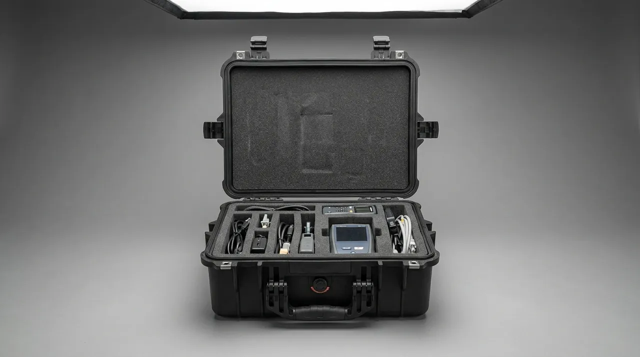
An equipment case protects the integrity of a die while it is not in operation. It cannot replace the safeguarding devices and management measures required on a press. This boundary should be written into the technical agreement and the training material so that nobody concludes that a dedicated case makes a press safe.
What a case cannot do.
- It cannot replace photoelectric guards, light curtains, two-hand controls, safety mats, or other safeguarding devices on the press.
- It cannot remove pinch, fall, or mechanical injury hazards during die changeover.
- It cannot substitute for periodic inspection, crack detection, and scrapping decisions on the die.
- It cannot repair an existing structural crack or fatigue damage.
- It cannot replace the interlock and safety gate management of a stamping automation line.
What a case can support.
- Rigid locating and clear labelling shorten the judgement time and trial-and-error moves during changeover, which reduces the exposure window.
- Weight and centre-of-gravity marking give the lift plan a factual basis.
- Status labels and an unpacking checklist turn die condition confirmation into a recorded, traceable step.
- A common insert architecture with insert numbering removes the improvised handling that comes from missing parts or wrong locations.
- Separate protected compartments for feeder components avoid the improvised dismantling and bypass work that follows component damage.
Safety note: changeover and feeder maintenance must follow the plant's established lockout-tagout, energy isolation, slide blocking, and lifting permit procedures. The case is one element of that system, not a substitute for it.
11. Sealing and Ingress Protection: An IEC 60529 and GB/T 4208 View
For a press die case, sealing addresses three intruders: dust, water vapour, and condensate. The classification framework is defined in IEC 60529 and its Chinese counterpart GB/T 4208.
| Rating | Dust | Water | Meaning for dies and feeder components |
|---|---|---|---|
| --- | --- | --- | --- |
| IP54 | Limited dust protection | Splash | In-plant short moves, dry workshops |
| IP55 | Limited dust protection | Water jet | General machining shops with washdown |
| IP65 | Dust tight | Water jet | Dusty shops, long road transit, common default |
| IP66 | Dust tight | Powerful water jet | High-pressure washdown or heavy rain exposure |
| IP67 | Dust tight | Short immersion | Flooded road sections or long open-air transhipment |
| IP68 | Dust tight | Continuous immersion | Special cases, specify depth and duration |
Selection logic. Do not chase IP67 by default. IP67 normally means a thicker gasket, higher latch preload, and more elaborate pressure equalisation, which affects ease of opening and case weight. Start from the worst credible case instead: will it be rained on, will it cross flooded ground, is the transhipment point under cover, is there high-pressure washdown in the shop? Then set the rating.
Cases containing electrical components. A case carrying a servo feeder, encoder, or control module should be at least IP65, with a pressure equalisation valve and desiccant. The reason is that the real enemy of electrical components is not immersion but condensation, and condensation is driven directly by internal humidity and temperature change.
Sealing versus pressure equalisation. A high sealing rating creates a significant pressure differential. A case cycling between 45 C by day and 10 C at night builds a marked negative pressure, opening becomes hard work, and the gasket is repeatedly compressed and released. A pressure equalisation valve allows gas to exchange slowly while blocking liquid water and dust, and is standard practice above IP65.
Gasket maintenance. The gasket is a wearing part. Inspect it periodically for hardness, rebound, and set, and replace it when it hardens, cracks, or takes a permanent compression set. Matching gasket material to environment is covered in waterproof case IP protection and seal design.
Documentation. Ask the supplier for a rating verification statement, type test report, or third-party conclusion, and put the sampling rule into the contract. Sampling and acceptance practice is described in custom case acceptance and AQL sampling.
12. Transport Validation: GB/T 4857, ISTA and MIL-STD-810H
The protection actually delivered by a die case has to be validated by transport testing, not by opinion.
The GB/T 4857 series. This is the basic Chinese test method system for transport packages, covering vibration, shock, stacking, and drop, and it suits domestic road transport scenarios. The stacking test matters especially, because storage stacking loads usually exceed transport loads, and heavy die cases are highly sensitive to stacking load. Key points are in GB/T 4857 transport packaging test methods.
The ISTA series. ISTA publishes transport packaging test procedures organised by distribution mode and package form. For die cases shipped as unitised loads, the ISTA 3 series unitised load procedures are the closest match. See ISTA transport testing procedure.
ASTM D4169. This standard uses a distribution cycle framework that combines handling, stacking, vibration, and shock into a complete test sequence, which suits export projects and situations where the acceptance basis must be common across parties. See ASTM D4169 distribution cycle testing.
Where MIL-STD-810H fits. This is a United States military standard for environmental test methods, frequently cited outside ISO-based industries as an environmental test basis. It must be stated clearly that citing MIL-STD-810H methods is an environmental test basis only. It does not indicate military certification, and it does not indicate compliance with any national military procurement requirement. For press die and servo feeder cases, the thinking in Method 514 (vibration) and Method 516 (shock) is useful as design input, but the test conditions must match the project's actual transport profile rather than being copied.
Validation points.
- Survey resonance first. Large progressive dies and long cases readily couple with the low-frequency vibration of road transport, so run a modal or sweep survey to identify the dominant resonances of the assembly.
- Evaluate case, insert, and die as one system. Testing the case alone or the die alone does not represent the real condition.
- Do a full functional check. After testing, inspect edge contours, guide mating faces, insert joint faces, roller outer diameters, and guide raceways, and re-measure die geometry and feeder positioning accuracy. Do not settle for whether the case itself survived.
- Evaluate electrical components separately. Vibration and shock limits for servo motors, encoders, and connectors should be specified separately from those for mechanical parts.
- Keep traceable records. Test conditions, sample identity, inspection method, and verdict should all be retained.
13. Labelling, Traceability and On-Site Unpacking
External labelling. At minimum include: die number and name, applicable product model, gross weight including the die, centre of gravity, lifting point identification, fork pocket positions, stacking limit, moisture and tip-over symbols, and orientation. Orientation and centre-of-gravity marks on heavy items should use high-contrast colours and remain readable in poor light. For long cases, mark both ends so that a single-direction read cannot cause a misjudgement.
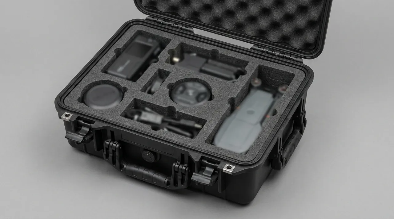
Internal manifest. Fix a manifest to the inside of the lid listing the component name, number, and quantity for each insert pocket. For segmented dies and feeder accessories, the manifest should state the assembly order. Its value is that anyone can complete a count and prepare for assembly without leaving the case to look up a drawing.
Status label. Use a four-field label: packing date, rust prevention method, expiry, and inspector. Both VCI and oil films have a finite life, and a status label turns expiry into a decidable fact.
Unpacking procedure.
- Before opening, check the case body, seals, and labels, and record anything abnormal.
- On opening, read the humidity indicator card and desiccant state before removing parts.
- Remove parts in manifest order so that adjacent compartments do not scrape each other.
- Inspect edges, guide mating faces, insert joint faces, roller outer diameters, guide raceways, and electrical connectors, then clean and re-oil or re-grease before use.
- Before mounting, verify shut height, blanking clearance, guide fits, feed pitch parameters, and ejection positions. Never assume the die is still at its as-shipped setting.
- Record any damage or deviation and feed it back to packaging and logistics so the loop closes.
Why traceability matters. Packaging and transport are where die damage concentrates and where the evidence chain is weakest. With a case number, a seal number, and an unpacking record, where the damage happened stops being a matter of argument. In subcontracting and OEM scenarios, that record also supports responsibility allocation and quality claims.
14. OEM/ODM Workflow, Acceptance and Reuse Management
Customisation workflow.
- Requirement input. Die and feeder component list with model, dimensions, weight, and centre of gravity; 3D models or physical samples; circulation mode (in-plant, inter-plant, export); transport modes; environmental conditions; moisture and ESD requirements for electrical components; compliance requirements.
- Design. Case size, insert architecture, locating and cushioning scheme, sealing rating, closure type, and labelling scheme.
- Prototype and verify. Trial fit the first insert, check clearances, ease of loading, and load paths on functional faces. For heavy dies and servo feeder cases, run vibration and stacking tests.
- Pilot use. Run the case on the real circulation route for a period and collect unpacking records and mounting feedback.
- Freeze and produce. Release the drawing and process, then move to volume supply.
- Reuse management. Establish case numbering, cycle counting, and replacement intervals for gaskets and inserts.
Acceptance points. Insert fit tolerance, locating repeatability, how the edge is loaded (whether the load lands on the plate outer rim), gasket compression, latch preload, material flammability rating, VCI expiry, completeness of labelling, and the antistatic properties of electrical component packaging. Build the sampling plan on AQL principles; the method is described in custom case acceptance and AQL sampling.
Reuse and life management. The hard shell normally lasts a long time, but inserts settle under repeated compression and gaskets age. Manage shell, insert, and gasket as three independent life items, and replace the whole case only when the shell cracks, distorts, or loses its closure function. The assessment approach is in protective case service life and reuse years.
Supplier selection. Press die cases are a classic non-standard custom plus volume supply category, so the supplier needs die design, foam machining, case moulding or assembly, and test coordination under one roof. An evaluation framework is given in how to choose a protective case OEM factory.
Cross-line standardisation with cookware and cutlery lines. A stamping line often supplies cookware, tableware, and appliance hardware at the same time, and dies are shared across several product lines. In that situation the cases should use one insert coding and labelling system so that tools can be shared across lines and changed over quickly, which reduces total tooling count. Unified removable partitioning is described in case removable divider system, and unified insert machining practice in custom EVA foam insert process.
What JUNZHJIA offers. As a brand of Kexin New Materials (Guangdong) Co., Ltd., JUNZHJIA supplies protective cases, tool boxes, and equipment cases to the hardware stamping and die industry on an OEM/ODM basis. Capabilities include conformal insert design and CNC machining from 3D die and feeder models, dedicated annular-support and edge-clear pocket geometry for stamping edges, isolated cushioned cavities and ESD packaging schemes for servo feeder assemblies, matched gaskets and pressure equalisation valves per case model, documentation supporting IP rating, material flammability rating, and transport testing, and volume acceptance against AQL rules. For dies above 800 kg, JUNZHJIA can supply an integrated case-and-pallet structure that supports lifting, forklift handling, and stacking in one design.
Frequently Asked Questions
Q: Should a press die edge be packed edge up, edge down, or edge sideways?
A: It depends on die structure and edge form, but the governing principle never changes: an edge must not touch a hard flat surface directly. Edge up is the first choice, because the edge carries no load and can be inspected the moment the case opens, and a low-strength strip or guard keeps objects out and prevents accidental contact. For highly integrated compound dies that cannot go edge up, edge sideways works, with lateral rigid supports carrying the load and the edge face held clear. If edge down is unavoidable, provide an annular rigid support face on the plate outer rim so the load lands on the plate body rather than on the edge contour, and never allow local loading on the edge itself. Whichever orientation is chosen, mark it on the outside of the case in high-contrast colour and write the first inspection step into the unpacking procedure. On progressive dies, also isolate adjacent station edges from one another so that a single chip cannot affect the whole process chain.
Q: A large progressive die weighs several tonnes. How should the case and lifting be designed?
A: For dies above 2000 kg, design the case and pallet as one integrated structure rather than placing a standard case on a generic pallet. The added stiffness measurably reduces low-frequency sway over long journeys, and it also allows the lift plan and forklift practice to be standardised. Six points govern the design. First, use a dense cross-ribbed base layout so that concentrated load spreads over a larger area. Second, place supports at roughly one fifth of the span in from each edge so the centre cannot sag. Third, always mark the centre of gravity, because a die with a high centre of gravity swings at the moment of lift and an unmarked centre of gravity leads to sling overload. Fourth, lifting points must be on the die body; the case provides protection only and is not a lifting device. Fifth, mark the fork pockets, because unmarked pockets get used incorrectly and the load path ends up somewhere the base was never designed for. Sixth, print the stacking load on the label, since storage stacking heights usually exceed transport stacking heights.
Q: Why do feeder rollers have such demanding packaging requirements?
A: Because both ends of a feeder roller are sensitive: the journal is the assembly datum and the outer diameter is the working surface, and neither may carry direct load. Once the outer diameter shows bruising, impact damage, or local rust spots, feeding slips cyclically, pitch fluctuates, and the product shows dimensional drift and burrs. Once a journal is damaged, coaxiality is out of tolerance after assembly, and the roller runs with runout and noise. There are further material issues: chrome plated roll surfaces are vulnerable to impact and to sulphur and chlorine contamination, while polyurethane coated surfaces dislike oil, ozone, ultraviolet, and heat, and take a permanent set under sustained compression. The correct approach is journal location with the outer diameter held clear, so the journals are the only support points and the working surface touches nothing. Rollers should be stored in separate compartments with enough spacing that they never rub during loading and unloading.
Q: What do servo feeders fear most in transport, and do they need special protection?
A: They fear shock and condensation above all, with dust and long-term vibration coming next. A servo feeder consists of a servo motor, a gearbox, and an encoder, and the encoder is the most fragile part. Impact causes signal fluctuation or permanent damage, and once the encoder is out of true the positioning accuracy of the whole feeder degrades irreversibly. Impact indentations in motor bearings make the unit run hot and fail quickly, and connectors loosen under vibration and produce intermittent faults. Condensation is a frequent problem on cross-climate transport: it lowers insulation resistance, corrodes terminals, and in severe cases causes a short circuit the moment power is applied. Specific measures include an integral cushioned seat to limit acceleration, a dedicated guard for the encoder that never shares a cavity with heavy components, connector locking or unit wrapping, a case sealing rating of at least IP65 with a pressure equalisation valve and desiccant, and keeping factory rust-preventive and cleanroom packaging on components and placing them in a separate cavity. After opening, let the unit reach room temperature before applying power.
Q: Is IP65 enough for a die case, and when is IP67 actually required?
A: IP65, meaning dust tight and protected against water jets under the IEC 60529 and GB/T 4208 framework, already covers the common situations in a stamping environment: dusty shops, shops with washdown, and ordinary long-distance road transport. It is the most common rating for press die cases. IP67 becomes necessary only when short-term immersion is a credible risk, for example when the route crosses sections prone to standing water, when the transhipment point is uncovered during heavy rain, or when in-plant movement passes through a washdown or flooded floor area. Moving to IP67 has side effects: a thicker gasket, higher latch preload, noticeably more effort to open, and a mandatory pressure equalisation valve, because otherwise the differential from temperature change makes opening difficult and fatigues the gasket. Note that a case carrying a servo feeder, encoder, or control module should be at least IP65 with a pressure equalisation valve and desiccant, because the real enemy of electrical components is condensation rather than immersion. In procurement, ask for the rating verification statement or type test conclusion and write the sampling rule into the technical agreement.
Q: Can an equipment case replace a press safeguarding system, and how should changeover safety be understood?
A: No, and it should not be presented as one. A case protects die integrity while the die is not running. Press safety during operation belongs to machine safeguarding and work management, and requires photoelectric guards, light curtains, two-hand controls, safety mats, lockout-tagout, and energy isolation as a complete set. Write this boundary into the technical agreement and the training material so that nobody concludes that a dedicated case makes the press safe. What a case can legitimately contribute is narrower but real: rigid locating and clear labelling cut the judgement time and trial-and-error moves during changeover; weight and centre-of-gravity marking give the lift plan a factual basis; status labels and an unpacking checklist turn die condition confirmation into a recorded, traceable step; a common insert architecture with insert numbering removes the improvised handling caused by missing parts or wrong locations; and separately protected compartments for feeder components avoid the improvised dismantling and bypass work that follows component damage. Treating packaging as part of changeover standard work is where its safety value actually comes from.
Q: Which transport tests validate press die cases and servo feeder cases?
A: Choose a standard combination that matches the transport modes, and make sure a functional check follows every test. For domestic road transport and warehousing, build on the GB/T 4857 series and prioritise vibration and stacking, because stacking loads usually exceed transport loads and are the main cause of case deformation; for large progressive dies, pay additional attention to the low-frequency vibration response. For export projects shipped as unitised loads, the ISTA 3 series unitised load procedures are a close match. Where the acceptance basis must be common across parties or the customer specifies a distribution cycle framework, ASTM D4169 applies. For air freight or extreme climate exposure, the environmental test thinking in MIL-STD-810H Method 514 for vibration and Method 516 for shock can be cited, with the explicit statement that this is an environmental test basis and not military certification. The design keys are: evaluate case, insert, and die as one system; after testing inspect edge contours, guide mating faces, insert joint faces, roller outer diameters, and guide raceways and re-measure die geometry and feeder positioning accuracy; specify vibration and shock limits for electrical components separately from mechanical parts; and record test conditions, sample identity, and verdict so the result is traceable.
Q: How long does a press die case last, and do inserts and gaskets need scheduled replacement?
A: Manage shell, insert, and gasket as three independent life items, because their failure mechanisms and service lives differ substantially. The shell usually lasts longest; provided it shows no cracks, no obvious distortion, and no structural damage at the closure, it can serve for years, with life driven mainly by cumulative handling cycles and load level. On heavy-duty cases, also watch the cross-ribbed base structure for fatigue cracking. Insert life depends on compression frequency and static load duration. Foam gradually loses rebound, which shows up as looser fits and reduced locating repeatability, and typically requires partial or full replacement after several years. Where a rigid support plus elastic cushion scheme is used, check in particular whether the cushion layer has collapsed to the point of no longer cushioning. The gasket is a wearing part; ageing appears as hardening, cracking, loss of rebound, and permanent compression set, driven by ozone, ultraviolet, oil contamination, and thermal cycling, so inspect it periodically and replace it on condition. In addition, VCI and oil films have finite lives and must be renewed on the interval stated on the label. Recording all three in a case log alongside unpacking records produces a predictable maintenance rhythm.
Q: Can hardware stamping die cases be shared with cookware and tableware production lines?
A: Yes, and they should be shared wherever possible, provided the tooling is standardised deliberately. A stamping line often supplies cookware, tableware, and appliance hardware at the same time, and dies are shared across several product lines. If each line maintains its own case and insert standard, the total tooling count grows, circulation becomes confused, and spare parts accumulate. Three practices work well. First, standardise the case size series, for example a small number of standard sizes graded by weight, rather than creating a new case for every product model. Second, standardise the insert coding and labelling system so that pocket numbering, manifest format, and status labelling are identical for the same die across lines, which enables cross-line sharing and fast changeover. Third, standardise acceptance and maintenance rules, including the AQL sampling plan, gasket replacement intervals, and case log format. The benefits are quantifiable: fewer tools overall, faster circulation, shorter counting time at unpacking, and clearer responsibility allocation in subcontracting. The material comparison and insert process referenced below can serve as inputs to that unified standard.
Conclusion & Related Reading
The essence of press die and feeder component protection is turning invisible loss into a managed process. Micro-chipping of an edge, guide post scoring, insert displacement, roller bruising, and lost servo accuracy do not announce themselves the way a cracked case does, yet their effect on production is more direct and more expensive: a die that will not dial in, feed pitch drift, out-of-tolerance burrs, and repeated clearance adjustment all resolve into yield, downtime, and delivery performance.
A competent hardware stamping die case has to solve five things at once: rigid locating to restrain the degrees of freedom, elastic cushioning to absorb vibration, sealing and rust prevention to control the environment, separate compartments to isolate precision feeder parts and electrical components, and labelling with traceability to build the evidence chain. For engineering and procurement teams, the productive comparison is not unit price but total cycle cost: arrival pass rate, unpacking and dial-in time, die repair frequency, downtime loss, and case reuse cycles.
Related Reading