


A single-aircraft case answers one question: how do we protect this airframe. A transport case faces a different order of problem. An operating unit usually deploys with two or more aircraft, several battery packs, a ground station, spares, and tools. If each item travels in its own container, departure means counting a dozen boxes, transit means handling each one, and arrival means reassembling the set in sequence. Consolidating the whole system into one case, or a small number of cases, so that it behaves as a single unit through transport, loading, storage, and field deployment — that is the engineering proposition of a UAV transport case.
This article approaches the subject from the structural design and manufacturing side of protective containers. It covers fleet payload lists and volume allocation, layering and isolated bays for multiple aircraft, container-level isolation for batteries and spares, stowage of ground stations and video terminals, large openings and load-bearing bases, casters and multi-person handling, lifting and forklift interfaces, and acceptance testing. Where standards are cited in this article they serve as test methods, not as a claim of certification. JUNZHIJIA's experience on these programs is that the difficulty is rarely the shell; it is deciding what goes in, how it is divided, and what comes out first.
The Engineering Question of Whole-System Transport
The fundamental difference between whole-system transport and single-aircraft protection is that the constraint shifts from protecting one device to coordinating a group of devices. When several aircraft, multiple battery formats, and ground equipment share one case, the design must satisfy four constraints at once. The first is volume: external dimensions are limited by vehicle bodies, aircraft cargo holds, and pallet modules, so the space cannot grow indefinitely and must be allocated carefully. The second is weight: consolidating raises total case weight sharply, so center of gravity, crew size, and running gear all need recalculation. The third is retrieval order: field deployment follows a fixed sequence, and the internal layout must let equipment come out in the order it is needed, or the efficiency advantage of consolidation is lost to rummaging. The fourth is compatibility: different devices tolerate temperature, humidity, and vibration differently, so they cannot simply be placed together by volume.
These four constraints shape the basic form of a whole-system case: modular isolated bays instead of one large cavity, layered structure instead of flat placement, and a defined retrieval sequence instead of casual packing. The single-aircraft adaptation logic is covered in Drone Transport Cases and Battery Cases: Agriculture, Inspection, Police and Fire Drones, and a whole-system scheme takes that as a starting point for system-level coordination.
Fleet Payload List and Volume Allocation
The first step in a whole-system scheme is a payload list built to device level rather than a vague note that several aircraft are involved. The list should itemize the number of aircraft and their packing attitude, each aircraft's weight and center of gravity, the number of battery packs and the weight of each, the composition of the ground station and its largest single component, the type and count of antennas, the list of spares and tools, and the volume of chargers, cables, and consumables. Only at this level does volume allocation have a basis.
A practical allocation method is to locate the incompressible items first. Aircraft and the ground station are rigid bodies whose envelopes define the primary zones. Battery packs can be positioned flexibly, but because they are heavy, their placement affects the overall center of gravity. Cables, consumables, and tools are compressible and suit the remaining space. A common error is assigning a fixed large bay to compressible items first, leaving the aircraft to squeeze into whatever remains. The correct order is to lock the primary envelopes, then fill the remainder with flexible items.
The other quantity easily overlooked is handling clearance. With equipment packed densely, the absence of room for hands and tools degrades usability quickly. Experience suggests reserving, in each bay's access direction, enough space for a hand and part of a forearm, and chamfering or flaring the opening so items do not scrape on every insertion. For field work with gloves, the allowance grows further. The sound approach includes clearance in the allocation table rather than checking what is left after layout.
Layering Multiple Aircraft: Shelves, Drawers, and Isolated Bays
When several aircraft share a case, layering is the most effective organization, far better than placing them side by side. Layering uses vertical space and sharply reduces the case footprint, which improves both handling and stacking. The basic unit is a shelf, each carrying one aircraft and its associated items, with defined locating and load-bearing structure between shelf and case so nothing shifts in transit and a full shelf can be lifted out as a unit.
Above the shelf level, the scheme subdivides into drawers and isolated bays. Drawers suit accessories, tools, and consumables, since pulling one open reveals the whole layer at once and retrieval is efficient. Isolated bays suit batteries and ground stations, which need separation or a fixed attitude. Layering must solve weight order first: heavy items low, light items high, because this lowers the center of gravity, improves rolling stability, and reduces lifting effort. Sequence comes second: if the workflow erects the ground station before launching aircraft, the ground station's bay belongs at the outermost or topmost position, so nobody has to move two aircraft out of the way first.
Shelf stiffness needs verification. The whole layer's load passes through four support points into the case walls, and an under-stiff shelf bows at full load, causing the upper equipment to interfere with the lower. Ribs or sandwich construction raise shelf stiffness, and locating features between shelf and wall prevent horizontal travel under vibration. The shelf handling interface deserves design too — handles, rails, or locating pins let one person remove a fully loaded shelf smoothly.
Container-Level Isolation for Batteries and Spares
In a whole-system scheme, batteries concentrate both risk and weight, and they must be handled separately. At the container level there are three goals: gather the packs into one physically isolated bay, give that bay a relatively independent thermal environment, and secure the packs against impact and vibration in transit. Physical isolation keeps batteries from crushing other equipment and gives routine pack swapping a fixed place and procedure, reducing mixed storage.
Bay placement must balance center of gravity against heat. Putting the battery bay low and near the middle of the case lowers the overall center of gravity, but packs retain heat after charging or recent use, so the bay should not sit hard against heat-sensitive equipment and should not be fully sealed without a ventilation path. A workable approach places an air gap or insulating liner between the battery bay and its neighbours and allows slow air exchange through a limited breathing path when the case is closed, provided that path does not compromise the overall protection rating.
Spares follow different logic. They include irregular shapes such as propellers and landing gear, and loose items such as tools and fasteners. The disciplined approach gives each category its own compartment with a shallow recess or elastic retainer so items do not collide in transit. Components that may carry residual oil or dust should be isolated with removable liner bags to keep neighbouring bays clean. More detail on independent battery transport appears in Isolated Transport and Isolation Design for Drone Battery Cases, and ground-station and video hardware stowage in Drone Accessory Cases: Controller, Propellers, Aerial Gear and Ground Station.
Stowing the Ground Station, Antennas, and Video Terminal
The ground station is usually the largest and heaviest single item in a whole-system case, and how it is stowed dictates both case dimensions and handling method. A ground station generally comprises a host unit, a display, a support frame, antennas, and a control panel, and it is normally folded and stripped of antennas before packing. The design must establish the folded envelope and provide separate support for host and display: the base carries the host, the sides locate the display, and a cushioning layer sits between them so impact cannot drive one into the other.
Antennas are the most damage-prone part of a ground station and the item most in need of dedicated provision. They are slender and connector-bearing, and they deform or damage at the connector under load. The robust approach gives each antenna its own slot or cradle, holds it vertically or in a fixed orientation, lines the slot with soft material, and adds an elastic retainer at the mouth to prevent escape. If antennas cannot be removed, they need generous clear space plus a flexible stop between ground station and case wall.
Video terminals and cables are handled frequently. A video terminal usually carries heat-sinking structure and connectors, so packing should orient connectors toward the access opening and keep them free of load, while cables should use removable bundling rather than forming random tangles. A useful habit is to give every cable its own home and put a loading diagram inside the lid, so field erection does not depend on trial and error. Accessories used with the aircraft are best stowed in a device-accessory-cable three-layer sequence, letting deployment proceed layer by layer.
Combined Insert Material Strategy
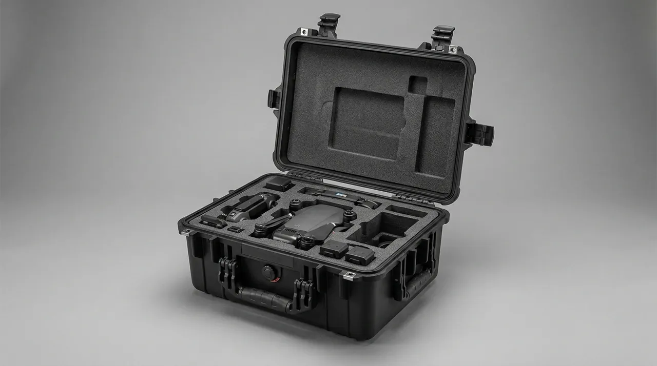
A whole-system insert rarely uses one material, because the case contains rigid bodies, precision equipment, and flexible items at the same time. A sound combination assigns materials by load-bearing role: a dense base plate with low compression set supports aircraft and ground station; side walls with good dimensional stability and wear resistance keep location accurate after many loading cycles; softer, resilient material at the top and around flexible items absorbs minor impacts and fills gaps.
Material combination must also consider contact compatibility. Hard material touching equipment directly can leave marks or wear coatings, so a soft pad normally sits between a rigid support and the device. Bonding method affects long-term reliability too, since adhesives can fail under temperature cycling, while mechanical fixing or keyed engagement is more stable. For programs that replace inserts frequently, a modular insert that can be removed piece by piece is better than one bonded solidly into the case.
Static control deserves separate consideration in whole-system cases. Electronics, cables, and spares coexist inside, and if insert material accumulates static charge through friction, discharge can affect sensitive circuits. Common practice applies antistatic material at the insert surface, or fits a grounding terminal inside the case and maintains a continuous conductive path. Whether static control is needed depends on how sensitive the equipment is, so the equipment owner should state the requirement rather than a default being assumed.
Case Structure: Large Opening, Ribs, and Load-Bearing Base
A whole-system case needs a large opening, because equipment is large and the access path is long. A large opening creates two structural problems: stiffness falls around the opening, making deformation under impact more likely, and the sealing path lengthens, making reliable sealing harder. The usual remedy is a reinforced frame around the opening plus matching ribs on the inside of the lid, so that when closed, lid and body form a box structure instead of being joined only by hinges and latches.
Rib layout must follow the load paths. The main loads in a whole-system case are equipment self-weight, stacking pressure, lifting loads during handling, and impact loads. Self-weight and stacking pressure travel mainly through the base and walls, so the base should be designed as a load-bearing structure, typically double-walled or thickened, with locating features matched to the pallet module underneath. Lifting loads act on handles or lifting points and must be routed into the primary wall structure to avoid local tearing. Impact paths depend on drop attitude, so the design should verify wall stress and insert displacement in the worst attitude.
The load-bearing base must also serve forklift and lifting needs. When a fully loaded case is too heavy to handle manually, forklift pockets or lifting points become a requirement rather than an option. Fork pockets should align with the center of gravity so the case does not tilt when lifted, and lifting points usually sit at the four corners, each rated for the total weight and the sling angle. The joint between base and wall is a stress concentration, so structural transitions or metal inserts should spread the load.
Casters and Multi-Person Handling
The weight of a whole-system case usually means it is moved by several people or by running gear. Caster design balances load sharing against steering agility. Four swivel casters steer freely but tend to wander when pushed, especially on slopes or uneven ground, while a two-fixed two-swivel combination tracks better over distance. Per-wheel rating should be total case weight divided by wheel count, multiplied by a dynamic factor, rather than a simple static split.
Multi-person handling requires predefined grip points. The usual provision is a top handle, side handles at both ends, and removable straps, so two or four people have defined places to hold and nobody is left without a grip. Handle positions should correspond to the center of gravity, keeping load close to vertical and reducing bending moment into the walls. For frequent vehicle loading, a retractable auxiliary handle or strap anchor on the side helps.
The caster-to-case joint governs long-term reliability. Caster mounting plates bolt directly to the base, and a base that is too thin allows bolts to loosen or the base to crack over long pushing. Thickening the base at the mounting zone or embedding a metal plate is the sound approach, combined with locking features at the bolted joint. For long-distance pushing over rough ground, a caster mount with damping reduces vibration reaching the case and its contents. Stacking and pallet coordination for whole-system cases is covered in Stacking and Pallet Planning for Protective Cases.
Lifting, Forklift, and Stacking Interfaces
When a whole-system case exceeds sensible manual handling weight, lifting and forklift provision moves from optional to essential. Lifting point design turns on three things: position, number, and per-point load. Positions should be symmetric about the center of gravity so the case hangs level; the usual count is four, with intermediate points where needed to reduce per-point load; and per-point load must be converted through the sling angle, since a wider spread increases the load in each sling.
Fork pockets must suit both fork dimensions and center of gravity. Once forks are inserted, the case should not tilt noticeably, so pocket position should coincide with or sit slightly offset from the case center of gravity. Pocket height must match common fork thickness, the inner surfaces need wear treatment so repeated handling does not spall the material, and the pocket zone needs local reinforcement to prevent the base cracking under offset load.
Stacking interfaces are the key to storage and transport efficiency. In storage a whole-system case is often stacked, and in transit it may be mixed with other cargo, so the top needs a load-bearing face and the base a locating face for stable stacking. The load-bearing face must spread upper weight into the walls rather than into the middle of the lid, and the locating face must prevent lateral sliding. For palletized use, recesses or locating feet matched to the pallet module keep the case from sliding. For air freight, restraint and pressure considerations are discussed in What to Consider for a Protective Case in Air Transport.
Sealing and Environmental Protection
Sealing a whole-system case is harder than a single-aircraft case because the opening is large, the perimeter is long, and the lid is more likely to distort locally when closed. The first task is ensuring that lid and body mate properly in the closed state, which requires a sufficiently stiff frame and evenly distributed compression from multiple latches. Too few latches leave the gasket under-compressed far from each latch, creating a leak path.
Gasket selection must consider operating temperature, weather resistance, and compression set. A whole-system gasket is long with multiple joints, and joints are common leak points, so molded corners or reliable hot-melt butt joints reduce weak spots. Cross-section also affects compression: a hollow or lipped profile forms a reliable seal under lighter compression, which suits large lids.
Environmental protection also includes internal moisture management. The internal volume is large, so the moisture carried in at packing time is greater and desiccant quantity and replacement interval should be calculated from net internal volume rather than estimated by rule of thumb. For long-term storage in humid regions, provisions for a humidity indicator and data logger plus a periodic inspection routine are worthwhile. A hygroscopic coating or replaceable liner on the inner wall further reduces condensation risk. Where equipment is electromagnetically sensitive, a shielding layer can be added to the liner, but this is a special requirement that should come from the equipment owner as a stated figure before design.
Air, Road, and Container Intermodal Transport
A whole-system case will cross several transport modes, each imposing different demands. Air freight cares about weight and restraint: weight drives freight cost and handling difficulty, so self-weight should be controlled as far as protection allows, while restraint needs lashing points or tie-down channels so the case cannot shift in the hold. Air freight also brings pressure and temperature changes, so sealing and valve configuration must match.
Road transport cares about vibration and impact: sustained vibration over long distances wears inserts and backs out fasteners, so loosening resistance and wear resistance belong in the design and periodic inspection belongs in the routine. For off-road programs, insert retention strength should be raised and shelf stability under bumping verified. Container intermodal transport cares about stacking and handling: once inside a container, the case is usually stacked with other cargo, so it needs sufficient compressive strength, and packing should follow the rule of heavy cases low, light cases high.
Intermodal transport also makes identification at handover important. The exterior should be clearly marked with program identification, a short contents summary, protection rating, and weight and center-of-gravity marking. Weight and center-of-gravity marking is especially important for lifting and forklift operations, because the operators are usually not the equipment users and can only rely on markings. Shipping documents belong in a fixed document pouch inside the case, covering the packing list, test records, and maintenance instructions for verification at handover.
Packing List and Inventory Management
The efficiency advantage of whole-system transport depends on always knowing what is inside. If every departure requires an open-case count, the convenience evaporates. A whole-system case therefore needs a matching list and management routine. The list belongs both inside and outside: an internal list on the lid for checking when open, and an external, replaceable label or pouch for quick confirmation without opening.
Inventory management turns on status records. Recording departure and return times, equipment condition, battery count and charge band, and any anomalies is worthwhile. For scheduled-maintenance programs, the record can note service items and due dates. For fleets of cases working together, each case should carry a unique number linked to its equipment in the list, avoiding mismatches between case and aircraft.
A further benefit of list management is early detection of shortages. A whole-system case holds many items, and a single missing piece is easy to miss until the field deployment stalls. Giving every piece a fixed position with a name label means any empty slot is immediately visible. This empty-slot visualization costs almost nothing but prevents many field surprises. For mission-configured programs, replaceable modular bays let different missions use different bay combinations, with the packing list switching per mission rather than the case being redesigned.
Inspection and Acceptance
Acceptance of a whole-system case is more complex than a single-aircraft case because it spans structure, system, and process. Structurally, check dimensions against the module, frame and rib layout, base load-bearing structure, lifting point and fork pocket position and strength, and hinge and latch reliability. Systemically, check that each isolated bay and insert matches its equipment, that battery bay isolation and thermal provisions are in place, and that ground station and antenna retention is reliable.
Process checks examine retrieval sequence and operating efficiency: how many steps from opening the case to full deployment, whether one person can complete the critical actions, whether extra tools are needed, and whether the lid stays stable when open. Actual users should take part in this evaluation, because designers rarely judge handling accurately from imagination. A full deployment drill is worthwhile at acceptance, starting from the transport state and recording the steps and time to reach a working state.
On documentation, request structural drawings, insert drawings, material specifications, test records, and maintenance instructions. Maintenance instructions matter especially for whole-system cases because there are many items and many wear parts, so inspection intervals and replacement criteria for gaskets, casters, inserts, and hardware must be explicit. For volume programs, test and drill the first article fully, sample later batches, and record critical dimensions and material lot numbers. General selection checks appear in Drone Case Buying Checklist and Drone Case Material Selection.
Common Failure Modes and Procurement Pitfalls
Whole-system cases show several characteristic failures. A shelf sagging is the first: upper equipment contacts the lower layer and drawer travel becomes difficult. The cause is insufficient shelf stiffness or poor support placement, prevented by raising stiffness and verifying at full load. Insert wear follows: equipment shifts inside its bay and location becomes imprecise, caused by surface wear from repeated loading, prevented by rigid locating elements at critical points plus periodic inspection.
Sealing leakage appears as condensation or dampness inside, usually caused by insufficient lid stiffness producing uneven compression or by poorly executed gasket joints. Prevention means stiffening the lid frame, using molded corner sections, and checking compression at intervals. Base cracking or caster loosening follows long-term overloaded pushing, prevented by thickening the caster mounting zone, embedding a metal plate, and using locking features. Loss of list control, where equipment goes missing or case and aircraft are mismatched, is a management problem that fixed positions and a visible list largely resolve.
Five procurement pitfalls stand out. The first is providing a device list without envelope data; whole-system schemes are extremely space-sensitive, and estimating without accurate envelopes produces dimensions that are wrong in one direction or the other. The second is comparing only shells and not internal zoning, which forfeits the whole point of consolidation. The third is ignoring retrieval order, which makes the case slower to deploy than separate boxes. The fourth is ignoring center of gravity, lifting points, and fork pockets, where the cost of an error is high. The fifth is ignoring maintenance and spares, since the many wear parts mean one gasket, caster, or insert can idle an entire case. Writing device envelopes, the deployment sequence, and maintenance requirements into the technical specification is the most direct way to avoid all five.
Closing Perspective: Transporting a System as One Unit
The goal of a UAV transport case is not to make a bigger box, but to manage an operating system as one unit. A fleet payload list gives volume allocation a basis. Layering uses vertical space. Isolating batteries and spares concentrates risk where it can be controlled. Dedicated stowage for ground station and antennas protects the fragile items. A large opening and a load-bearing base give the case structural integrity. Running gear, lifting points, and stacking interfaces plug it into a real logistics chain. When these elements work together, departure stops being a burden of counting and handling and becomes an orderly transfer of a complete system. JUNZHIJIA's habit on whole-system programs is to write the deployment sequence into the design inputs, because in the end a case is judged by those few minutes in the field.
Frequently Asked Questions
Q: When should a whole-system transport case be used instead of separate cases for each aircraft? A: The decision follows equipment count, coordination level, and operating rhythm rather than case size alone. When an operating unit has two or more aircraft and deploys them together with a ground station, spare batteries, and tools, a consolidated case usually wins, because counting and handling drop sharply and field deployment can follow a preset sequence. Conversely, when a mission uses one aircraft with few accessories, or when devices are carried by different people who meet at the site, separate cases are more flexible and avoid growing the box until mechanical handling becomes mandatory. Transport limits matter too: if external dimensions are constrained by a vehicle body or a cargo door, the consolidated scheme may be impractical, and several medium cases working in parallel become the better answer. A practical way to decide is to run a simple comparison. Estimate the counting and handling time saved by consolidation against the extra handling difficulty created by higher weight, then weigh that against how often the unit deploys. For high-frequency, fixed-fleet, fixed-sequence operations, the consolidated approach usually pays.
Q: With several aircraft in one case, how do we stop them from colliding? A: The answer is layering and independent location rather than packing tight. First, each aircraft should have its own shelf or isolated bay, so no two aircraft share a contact surface and the risk changes from whether one presses on another to whether a shelf shifts. Second, the shelf and bay must be located: a shelf needs horizontal restraint through rails, locating pins, or surrounding edges so it cannot travel as a unit under vibration. Third, equipment must be retained within its own bay, normally with matched support at critical load points, handling clearance in non-load areas, and elastic retainers against vertical bounce. Fourth, interlayer isolation helps: a soft pad under the shelf prevents the upper device base from hard contact with the lower device top during bumping. Finally, shake the packed case once to confirm there is no perceptible shelf movement or contact noise. That single check is more direct than any drawing.
Q: How should the battery bay be designed in a whole-system case, and how does it relate to the aircraft bays? A: The battery bay should be designed as a relatively independent sub-unit, separated from the aircraft bays physically and thermally. Physical separation keeps batteries from crushing aircraft and reduces how often aircraft bays must be opened for routine pack swaps, cutting the dust and moisture exposure of the airframes. Thermal separation gives the battery a more stable temperature environment, since packs are relatively temperature-sensitive while other equipment may not require the same conditions. In position, the battery bay should sit low and toward the middle of the case, which lowers the overall center of gravity and eases one-person handling, while avoiding direct contact with the floor or the outer wall to slow external temperature conduction. Structurally, the bay needs matched support and locating blocks plus an adjustable clamp to limit vertical bounce, because the battery pack is often the heaviest single item. The bay opening should also be offset from other bays so packs can be accessed without raising the main lid, which is very practical in operations that swap packs frequently.
Q: How should the ground station and antennas be secured, and do they need a separate bay? A: A separate bay or dedicated zone is advisable, because their shape, weight, and sensitive points differ completely from the aircraft. The ground station is usually the largest single item and is normally folded and stripped of antennas before packing, so the design inputs must include the folded envelope rather than the deployed dimensions. For retention, let the base carry the host weight, locate it laterally, and place a cushioning layer between host and display so impact cannot drive one into the other. Antennas should have individual slots or cradles, held vertically or in a fixed orientation, lined with soft material, with an elastic retainer at the mouth to stop escape; if they cannot be removed, they need generous clear space and a flexible stop. Packing the ground station in the same cavity as the aircraft usually produces one of two bad outcomes: the aircraft cavity is oversized to accommodate the ground station and space is wasted, or the ground station shifts in transit and strikes the aircraft. A dedicated bay adds a little complexity and weight but delivers clear retention and faster access.
Q: When a whole-system case is very heavy, how should lifting points and fork pockets be positioned? A: The principle is to keep both lifting and forklift loads as close to the center of gravity as possible while keeping the case level when lifted. Lifting points usually sit at the four corners, positioned symmetrically about the horizontal projection of the center of gravity so the case hangs level; per-point load must be converted through the sling angle, since a wider spread increases the load in each sling, so points should not be spread too far apart. Lifting points must be routed into the primary load-bearing structure, usually through metal inserts or thickened zones, to avoid tearing thin wall sections. Fork pocket position should coincide with or sit slightly offset from the horizontal center of gravity so the case stays stable once lifted; pocket height must suit common fork thickness, and the inner surfaces need wear treatment plus reinforcement at the mouth to prevent spalling and base cracking under repeated handling. The exterior should also carry clear weight and center-of-gravity markings, because the people executing lifting and forklift operations are usually not the equipment users and can only rely on the markings. That last point is among the most commonly neglected in whole-system safety.
Q: Why is sealing a whole-system case harder than sealing a single-aircraft case, and how is reliability achieved? A: The difficulty comes from three sources. First, a large opening means a long seal perimeter, and any poorly mated point becomes a leak path. Second, a large lid has relatively low stiffness and tends to distort away from the latches when closed, leaving the gasket under-compressed. Third, a long gasket has many joints, and joints are weak points. The remedies match the three. First, design both body and lid as box structures, with a reinforced frame around the opening and matching ribs inside the lid so closed stiffness keeps the faces mated. Second, calculate latch count and position so compression is even around the perimeter, and favour adjustable engagement so compression can be restored as the gasket ages. Third, form corners and joints with molded sections or reliable hot-melt butt joints, and choose a hollow or lipped cross-section that seals under lighter compression. Finally, because internal volume is large and carries more moisture in at packing time, calculate desiccant quantity from net volume rather than estimating by experience.
Q: Does a whole-system case need static-control treatment, and how is that decided? A: Whether static control is needed should come from the equipment owner as a stated requirement based on the sensitivity of the contents, not from a default assumption. A whole-system case usually holds electronics, cables, and various spares, and if insert material accumulates charge through repeated handling, discharge can damage sensitive circuits. Such damage is often not obvious but reduces reliability. Where the owner specifies static control, common implementations include insert material with a defined surface resistance, a grounding terminal inside the case with a continuous conductive path, and avoiding packing accessories that generate charge readily. In environments sensitive to charge accumulation, a conductive liner that routes static to the ground point can be added. Where no requirement exists, adding antistatic material blindly is not advisable either, because static-control materials have different mechanical behaviour from standard foam and an unplanned substitution can degrade cushioning. The sound approach confirms the static requirement, grounding method, and verification method at the design-input stage and includes them in acceptance documentation.
Q: What should acceptance testing cover for a whole-system transport case, compared with a single-aircraft case? A: Whole-system acceptance adds system and process layers to the structural checks of a single-aircraft case. Structurally, check case dimensions against the module, frame and rib layout, base load-bearing structure, lifting point and fork pocket strength, hinge and latch reliability, and evenness of seal compression. The system layer is specific to consolidation: verify that each isolated bay and insert matches its equipment, that battery bay isolation and thermal provisions are in place, that ground station and antenna retention is reliable, that shelves do not sag at full load, and that there is no interference between devices. The process layer checks the deployment sequence: how many steps from opening to a working state, whether one person can complete critical actions, whether extra tools are needed, and whether the lid is stable when open. A full deployment drill at acceptance, timed from the transport state to a working state, with actual users taking part, is strongly recommended. Documentation should add maintenance instructions to the structural drawings, insert drawings, material specifications, and test records, stating inspection intervals and replacement criteria for wear parts.
Q: What are the most common mistakes when procuring a whole-system transport case? A: Five dominate. First, providing a device list without individual envelope data; whole-system schemes are extremely space-sensitive, and estimating without accurate envelopes produces dimensions that miss in one direction or the other. Second, comparing only the shell and not the internal layout, which forfeits the point of consolidation, since a generic large cavity delivers none of the efficiency advantage. Third, ignoring retrieval order, which makes the case slower to deploy in the field than separate boxes; only writing the actual workflow into the design inputs prevents this. Fourth, ignoring center of gravity, lifting points, and fork pockets, where a handling error is costly, so these must be designed around the real center of gravity with strength verification. Fifth, ignoring maintenance and spares, because the many wear parts mean one gasket, one caster, or one insert section can idle the whole case, so the spares list, supply route, and replacement interval belong in the order. Writing device envelopes, the deployment sequence, and maintenance requirements into the technical specification is the most direct way to avoid all five.