

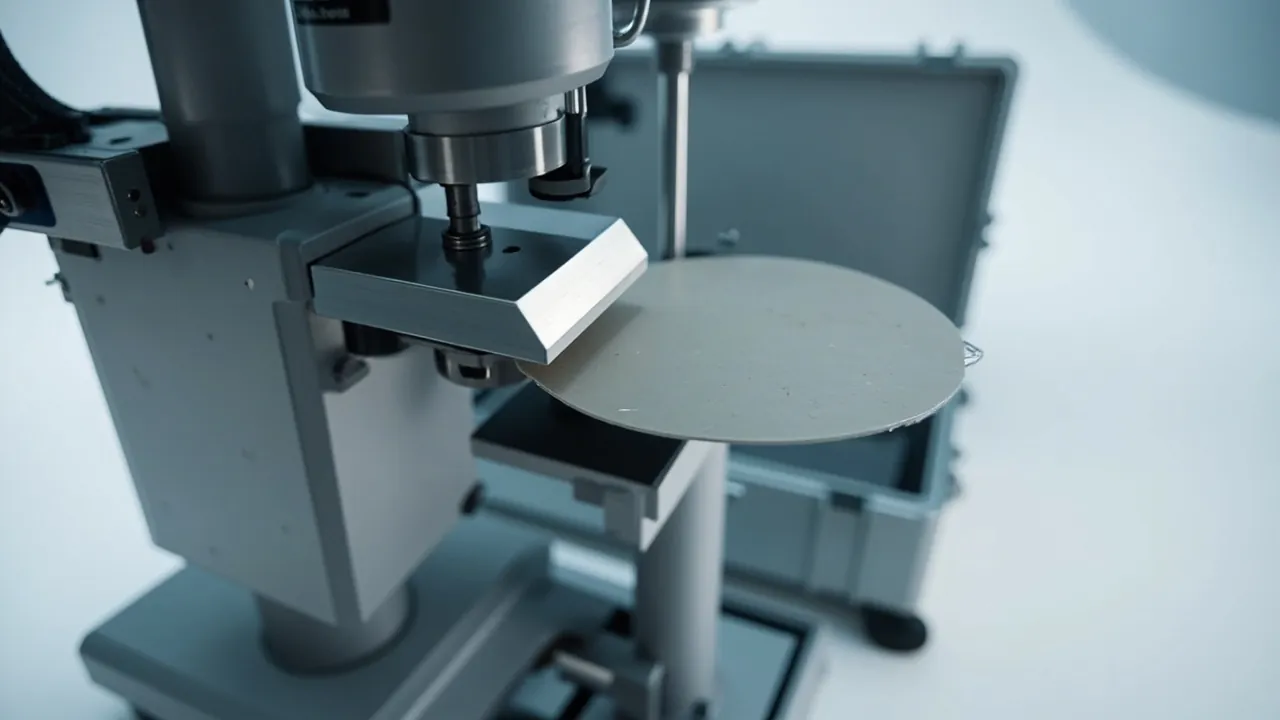
Wafer dicing spare parts logistics rest on a principle that differs from most semiconductor equipment: the spindle and the blade must be packaged separately, shipped separately, and accepted separately. The two work together once installed, but the mechanisms that damage them are entirely different. A spindle is vulnerable through its bearing system — micro-vibration and contamination. A blade is vulnerable through edge chipping and moisture corrosion. Put them in the same cavity and the mass of the spindle applies continuous pressure to the blade, while the blade's sharp edge can score the spindle flange face. The central conclusion of this article is that a dicing equipment component case must be designed along three independent lines — high-speed rotating precision parts, ultra-thin brittle consumables, and an ultra-clean environment — and then bound together by a common case body and cleanliness regimen.
Dicing is a critical back-end step in wafer manufacturing, and cut quality determines die chipping size and bending strength directly. Spindle rotation accuracy, blade edge condition, and coolant flow distribution jointly determine kerf quality. If any one of the three changes in transit, the result at the saw is larger chipping, kerf offset, or a whitened cut line, and these symptoms are usually attributed to process parameters first, with spare part condition traced last.
This article works in sequence through spindle, blade, flange and blade cover, motion stages, and alignment vision, and it sets out cleanliness mapping, insert compartmentalization, micro-vibration control, corrosion and humidity management, and verification and cleanliness re-test practice. It is written for equipment engineers at wafer fabs, dicing tool builders, and spare parts suppliers.
Table of Contents
- Why Spindles and Blades Must Ship Separately
- Component Inventory and Transport Risk Map for Dicing Equipment
- Dicing Spindles: Protecting Air Bearings and High-Speed Rotating Assemblies
- Dicing Blades and Bladed Wheels: Packaging Logic for Ultra-Thin Brittle Consumables
- Flanges, Blade Covers, and Coolant Circuit Components
- Work Tables and Motion Stages: Anti-Migration Design
- Alignment Microscopy and Height Measurement Modules
- Insert Design: Multi-Point Equal-Stiffness Support for Ultra-Precision Parts
- Micro-Vibration Control: From the Drop Spectrum to Low-Frequency Vibration
- Cleanliness, Static, and Cleanroom Unpacking Discipline
- Corrosion and Humidity: Protecting the Metal in Spindles and Blades
- Interfacing With the Wafer Carrier System
- Verification Plan and Cleanliness Re-Test
- Frequently Asked Questions
- Conclusion and Related Reading
Why Spindles and Blades Must Ship Separately
Start with the sensitivity mechanisms of the two parts.
A dicing spindle is a high-speed precision rotating assembly. Most use air bearings or high-precision angular contact bearings, with speeds reaching tens of thousands of revolutions per minute. Air bearing load capacity depends on a micron-scale air film gap, and that gap is extremely sensitive to contamination and distortion; rolling bearing versions depend on preload state and raceway integrity. The failure signature for a spindle is loss of rotation accuracy, appearing as increased radial runout and axial endplay, and ultimately as uneven kerf width and larger chipping.
A dicing blade is a different extreme. It is sintered from diamond abrasive and a bond matrix, with thickness typically between 20 µm and 100 µm, and the edge region is thinner still. That geometry makes it highly prone to edge chipping under lateral force or impact. After chipping, cutting capability drops sharply, and the dislodged abrasive becomes a contamination source that scores the wafer surface.
Putting both in one cavity creates two problems at once. First, spindle mass is typically hundreds to over a thousand times that of a blade. Under transport shock the spindle generates inertial loads far beyond what a blade can take, and if the two make contact, blade damage is nearly certain. Second, the blade's sharp edge scores the mating face of the spindle flange, and the flatness of that face is the foundation of spindle assembly accuracy. Separate packaging is therefore not the safer option; it is the only workable one.
After separation, one further scheduling point matters: spindles and blades should not arrive in the same delivery batch. Once a spindle is mounted on the tool it still needs running-in and rotation accuracy confirmation, and installing a blade before that is complete serves no purpose. Separate packaging also makes it natural to dispatch in assembly order.
Component Inventory and Transport Risk Map for Dicing Equipment
Before packing, inventory components by module and rank them. Dicing spares range from a blade weighing tens of grams to a gantry spindle mount weighing over a hundred kilograms.
| Assembly Group | Critical Geometry | Dominant Transport Risk | Countermeasure | Post-Transit Acceptance | ||
|---|---|---|---|---|---|---|
| --- | --- | --- | --- | --- | --- | --- |
| Dicing spindle body | Air-film gap, raceway form | Indentation, particle ingress | Sealed cleanroom bag, port plugs | Radial runout within spec | ||
| Spindle drive and encoder | Grating alignment, connector seating | Vibration, connector strain | Separate cable channel | Speed feedback stable | ||
| Dicing blade and wheel | Edge integrity, thickness | Chipping, moisture attack | One cradle per blade | Edge intact, runout checked | ||
| Blade flange and clamps | Mating face flatness | Scoring, point loading | Matched-face support, face cap | Flatness re-measured | ||
| Blade cover and guards | Wall concentricity | Denting under external pressure | Support from inside the wall | Concentricity verified | ||
| Coolant nozzle and tubing | Orifice size and angle | Blockage, tube collapse | Cleanroom cap, blown dry | Flow distribution tested | ||
| Work table and chuck | Table flatness, micro-pore patency | Local depressions, blocked pores | Full-surface even support | Holding force distribution checked | ||
| X/Y/theta stages and rails | Raceway, air gap | Precision loss | Travel blocks, three-point support | Repeatability verified | ||
| Alignment vision and height module | Beam path, optical centre | Contamination, datum shift | Rigid sleeve, isolated cavity | Imaging centre and zero checked | ||
| Wafer carrier and transfer parts | Contact surfaces | Static charge, warping | Dissipative materials | Charge and flatness checked |
This table is used differently from the ones for other equipment categories: dicing equipment has an unusually large number of very-high-sensitivity components. Spindle, blade, stages, and vision all fall in the top band. That means the design cannot be simplified by isolating only the sensitive parts; every high-sensitivity component needs its own support and cushioning scheme.
One exception is worth remembering: cleanliness requirements are harder to relax than mechanical requirements. Mechanical parameters can be improved by adding cushioning, but once cleanliness is compromised at the packaging stage it usually requires recleaning to restore, and recleaning itself carries risk for both optical parts and spindles.
Dicing Spindles: Protecting Air Bearings and High-Speed Rotating Assemblies
Dicing spindles divide into air-static and rolling-bearing types. The packaging requirements differ in emphasis, but the common ground outweighs the differences.
For an air-static spindle, the critical items are the air film gap and the restrictor orifices. The gap is typically on the order of a few microns, and any distortion or contamination changes the pressure distribution of the film, which alters load capacity and stiffness. Restrictor orifices are very small, and a single particle can cause a local blockage that shifts the spindle's vibration signature. Packaging for this type must therefore treat internal cleanliness as the primary objective: plug all air ports with cleanroom plugs, seal the entire spindle inside a cleanroom bag, and ensure no material inside the case can shed.
For a rolling-bearing spindle, the critical items are preload state and raceway integrity. Transport shock indents the raceway, and indentation converts into a vibration excitation at high speed. These spindles are extremely shock-sensitive and their allowable acceleration usually must be held at a low level.
Shared packaging points:
- Treat the spindle as its own packaging unit. Do not share a cavity with other components, and preferably not a case either. If a shared case is unavoidable, use an isolated sealed inner box.
- Restrict axial and radial freedom, but do not apply radial clamping force. A spindle's cylindrical surface should not be directly clamped by the insert, because clamping force distorts the housing, which in turn affects internal clearance. The correct approach is axial location on end faces or a flange, with only small-clearance radial restraint.
- Place support points near rigid structure. Support should land on the spindle housing or flange, never on a slender section.
- Give drive and encoder cables their own channel. Compressed or whipping cables cause conductor fatigue and stress at connectors.
- Close all air and water ports. Use plugs matched to the cleanliness class and record the plug specification so each item can be removed in a controlled way at installation.
Spindle allowable shock values should come from the maker's data. Where none is provided, take the more conservative band than for a general machine tool spindle, because a dicing spindle runs far faster and an equivalent indentation produces a stronger excitation at high speed. For general precision spindle protection logic, read alongside the packaging approach for CNC machine tool spindles; a dicing spindle is the higher-speed, stricter-cleanliness branch of that family.
Dicing Blades and Bladed Wheels: Packaging Logic for Ultra-Thin Brittle Consumables
Blade packaging faces an apparently contradictory set of requirements. It must prevent edge chipping yet must not press on the blade. It must resist moisture and corrosion yet must avoid materials that can contaminate the edge.
| Blade Type | Structural Feature | Main Brittle Point | Packaging Priority | Post-Transit Checks |
|---|---|---|---|---|
| --- | --- | --- | --- | --- |
| Metal-bond diamond blade | Sintered abrasive, very thin | Edge chipping | Individual division, zero hard contact | Edge appearance, outer diameter runout |
| Resin-bond blade | Softer bond, moisture sensitive | Distortion, moisture swelling | Dry sealing, light shielding | Thickness change, edge integrity |
| Electroplated diamond wheel | Thin substrate, plated edge | Plating flaking | Contact-free packaging | Plating integrity |
| Hub-type blade | Flanged hub | Scored hub mating face | Hub face protection | Mating face flatness |
| Ultra-thin blade | Thickness near the lower limit | Bulk distortion | Individual carrier | Flatness, cracking |
The logic reduces to four points.
Point one: individual support for every blade. Each blade should be carried by its own cradle or division, never stacked. When stacked, the lower blade carries the weight above, and ultra-thin blades have very low compressive and bending capacity, so sustained load produces permanent distortion.
Point two: zero hard contact. A blade must never contact hard material — case wall, metal part, or another blade — directly. Cradle contact surfaces should use a low-shedding soft material, and contact locations should stay clear of the edge region.
Point three: control humidity rather than relying on an oil film. The traditional approach applies anti-rust oil, but an oil film contaminates the edge and changes coolant distribution at the saw. A better approach uses vapor-phase corrosion inhibitor together with a controlled dry environment, holding internal relative humidity low while leaving no oily residue.
Point four: shield light and hold temperature. Some resin-bond blades are sensitive to light and heat, and long exposure ages the bond. Packaging should provide light shielding and avoid prolonged storage at elevated temperature.
One blade acceptance step is commonly skipped: measure outer diameter runout and inspect the edge before mounting. Outer diameter runout reflects directly whether the blade distorted in transit, and edge inspection is best done under magnification. Both steps are inexpensive and prevent mounting an already damaged blade on a spindle.

Flanges, Blade Covers, and Coolant Circuit Components
These three component families all participate directly in the geometry and fluid state of the cutting zone, so their distortion and contamination both affect kerf quality immediately.
Blade flanges determine blade mounting flatness and radial location. Once the mating face develops a dent or burr, the blade develops axial wobble, which appears as kerf width fluctuation. Flange packaging priorities are face-contact support and mating face protection: use a support face matching the mating face geometry to avoid localized loading, and fit a protective cover to the mating face using a material that will not shed.
Blade covers and guards are often thin-wall stainless steel or engineering plastic, and their impact resistance depends on their shape. The rule for thin-wall parts is to support from the inside: place support along the load direction inside the cover so shock travels through the support instead of bending the thin wall. Wrapping and compressing from outside actually dents thin-wall parts more easily. This is the opposite of the logic used for heavy structural parts and deserves particular attention.
Coolant nozzles and tubing risk blockage and distortion. Nozzle orifices are small, and particles or scale change the flow distribution, while uneven flow leaves the cutting zone under-cooled and causes thermal damage. Fit cleanroom covers to nozzles and cleanroom plugs to line ends during packaging. If residual water remains in a line, long storage can promote microbial growth or corrosion, so blow the lines dry before dispatch.
| Component | Critical Geometry | Failure Consequence | Protection Measure | Re-Check Method |
|---|---|---|---|---|
| --- | --- | --- | --- | --- |
| Blade flange | Mating face flatness | Blade wobble, kerf width fluctuation | Matched-geometry support, mating face cover | Flatness measurement |
| Blade cover | Concentricity to spindle | Interference, protection failure | Internal support, no external pressure | Concentricity and appearance |
| Coolant nozzle | Orifice diameter and angle | Flow distribution change, thermal damage | Cleanroom cover, blow dry | Flow testing |
| Tubing and fittings | Seal face at the joint | Leakage, unstable pressure | Cleanroom plugs, no compression | Leak check |
These parts share one packing pitfall: they are small enough to be used as filler in leftover voids. That is high risk, because void space usually sits next to heavy components and relative motion in transit causes repeated collisions. Each part family should have its own cavity, even at the cost of a larger case.
Work Tables and Motion Stages: Anti-Migration Design
The work table carries the wafer, and its flatness and holding capability determine cutting depth consistency. The X/Y/theta stages position the cut path. Both are datum-maintained precision parts, and the core transport risk is datum shift.
A work table fails in two ways. First, chuck surface flatness changes: a porous ceramic chuck develops micro-depressions under localized load, affecting wafer conformance. Second, the vacuum path changes: if the chuck's internal micropores are blocked by debris or particles, holding force distribution becomes uneven.
A motion stage fails mainly through rails and drives. Rail raceway indentation, linear motor air gap change, and lead screw axial clearance all reduce positioning accuracy.
Anti-migration design is the key to packaging these parts. Anti-migration means mechanically constraining moving parts to a defined position for transport, rather than relying on friction to hold them still.
In practice:
- Fit transport blocks. Use removable rigid blocks to limit travel on movable slides and rotary axes. The customer removes them at installation, so they need prominent marking and a line item on the packing list.
- Do not rely on friction. Holding a moving part only by friction pads or a clamp allows gradual slip under sustained vibration, and the slip amount cannot be predicted.
- Three-point support with face contact. As with other precision motion parts, use statically determinate support so the insert does not itself cause distortion.
- Mark lifting and load-bearing points clearly. A heavy stage case needs explicit lift markings so that lifting gear uses the intended points.
- Ship factory accuracy data. Include factory measurement records for repeatability, flatness, and holding force distribution so they can be compared on arrival.
For packaging and transport requirements on precision measurement parts, see the packaging approach for metrology standard artifacts. A work table's accuracy class is comparable to metrology equipment, so the packaging logic transfers well.
Alignment Microscopy and Height Measurement Modules
The alignment vision and height measurement modules determine how accurately the cut path aligns with existing features on the wafer. Their shared weak point is the datum that joins optical and mechanical elements.
Alignment vision comprises a camera, lens, illumination, and adjustment mechanism. Should the lens and camera body change position relative to each other, the imaging centre moves; uneven illumination then changes how edges are detected; and if the adjustment mechanism shifts in transit, even by a few tens of microns, the alignment datum changes.
The height module typically uses a laser displacement sensor or a contact probe to measure wafer surface height for depth control. The laser sensor's beam path is sensitive to both contamination and displacement, and a single dust particle on the window can produce a measurement jump, while a contact probe is vulnerable to stylus deformation under load.
Packaging points:
- Package optical modules as a unit. Do not separate camera and lens; cap the interface.
- Dedicated cavity and dedicated cushioning. Optical parts should not share a cavity with metal parts, nor share a cushioning system with heavy items.
- Fit a rigid protective sleeve to contact probes. A probe needs a rigid sleeve in transit that is stiff enough to absorb accidental impact while not pressing on the stylus.
- Dry and prevent mold. As with other optical parts, place enclosed desiccant in the case with a humidity indicator card to avoid mold growth in long storage.
- Ship calibration data. Include records for imaging center, zero position, and the environmental conditions at calibration, so they can be compared on arrival.
One caution: optical parts usually carry stricter cleanliness requirements than mechanical parts, while the dicing cutting zone itself contains abundant debris and coolant mist. Optical modules should therefore be protected to a higher level during transport and storage than they experience in their working environment — a requirement that is frequently underestimated.
Insert Design: Multi-Point Equal-Stiffness Support for Ultra-Precision Parts
The insert is the technical center of the case. For dicing equipment, the design objective can be summarized as multi-point equal-stiffness support.
Multi-point means support should not concentrate at a few locations. Concentrated support concentrates stress near the support points and creates local distortion, while distributed support spreads the load. For spindles, flanges, and work tables, support points should cover as much of the rigid contour region as possible.
Equal stiffness means the effective stiffness at each support point should be similar. If some points are much stiffer, shock load preferentially travels through the stiff points and creates local high stress. A practical way to achieve equal stiffness is to use identical material, thickness, and compression area at each support, never mixing foams of different densities.
| Component Feature | Support Strategy | Practice to Avoid | Reason |
|---|---|---|---|
| --- | --- | --- | --- |
| Cylindrical spindle | Axial end-face location plus small-clearance radial restraint | Radial clamping | Clamping force distorts the housing |
| Thin-wall blade cover | Internal support with external clearance | Wrapping and compressing from outside | External pressure dents the thin wall |
| Flat flange | Matched-geometry face support | Three-point local support | Local support changes flatness |
| Porous ceramic chuck | Uniform full-surface support | Edge-point support | Local loading creates depressions |
| Optical module | Low-stiffness suspension | Rigid compression | Compression transmits high acceleration |
| Irregular assembly | Compartmentalization with datum replication | Wrapping the whole unit | Wrapping makes the load path uncontrollable |
Inserts are usually CNC-machined, most commonly in closed-cell foam that machines cleanly. For components with very high cleanliness requirements, the contact layer needs cleanroom-grade material. For complex shapes or very small batches, a modular approach of standard cavities plus interchangeable adapter blocks reduces per-unit machining cost. For the general design workflow, see the custom insert design and validation workflow.
There is one further cleanliness-related insert constraint: an insert should not contain closed cavities. Air trapped in a closed cavity expands and contracts with temperature and pressure changes in transit, which can draw contaminants in or push them out, and it releases accumulated particles when the case is opened. Design cavities to be open or vented.
Micro-Vibration Control: From the Drop Spectrum to Low-Frequency Vibration
Dicing equipment components are more vibration-sensitive than most, because their failure mechanism is accuracy degradation, and accuracy degradation is the accumulation of vibration energy.
Vibration control has to address three frequency bands, each mapping to a different transport stage.
| Frequency Band | Main Source | Effect on Components | Control Method |
|---|---|---|---|
| --- | --- | --- | --- |
| High (tens of Hz and above) | Road excitation, engine vibration | Loosened fasteners, surface fretting | Damping layer, face contact |
| Medium (a few Hz to tens of Hz) | Trailer suspension, handling impact | Cushion compaction, cumulative displacement | Cushion curve matching, restrict freedom |
| Low (below a few Hz) | Ship roll, aircraft attitude change | Large displacement, package tipping | Restraint, securement, stacking check |
High-frequency control focuses on damping rather than stiffness. Increasing stiffness transmits vibration to the component; increasing damping converts vibration energy into heat. Common damping methods include placing a damping material between the cushion layer and the structural layer, or using a foam with high intrinsic damping.
Medium-frequency control focuses on cushion curve matching. If the static stress of the cushion at the given load falls in a low-efficiency region, performance will be poor. Material density and thickness should be selected from the cushion curve rather than chosen by habit.
Low-frequency control focuses on restraint and securement. Low-frequency vibration involves large displacement, and the cushion may bottom out completely, at which point it no longer functions and the only protection left is the restraint structure and securement method. Sea and air freight deserve particular attention here.
One parameter concerns the package itself: the natural frequency of the packaging system should avoid the dominant transport excitation bands. If the natural frequency falls inside an excitation band, the package amplifies vibration instead of attenuating it. The measurement method is normally a swept-sine vibration test on the package, observing where the content response peaks.
Detailed environmental test profile design can follow the relevant methods in MIL-STD-810H. To prevent any misunderstanding: MIL-STD-810H enters this article only as a catalogue of environmental test methods, and citing it does not make any packaging product or design military-certified. For export programs, the distribution cycle simulation approach is also useful. Where components are sensitive to pressure change, sealing and equalization practice is covered in sizing an equalization valve for a sealed case and the practical boundaries of IP ratings on equipment cases.
Cleanliness, Static, and Cleanroom Unpacking Discipline
Dicing sits in the back end of wafer manufacturing and usually runs in a controlled clean environment. Packaging's role here is to preserve cleanliness and manage the transition.
The cleanliness mapping principle is that the target environment class determines both the interior surface requirement and the opening location. Dicing areas commonly run between ISO 14644-1 Class 6 and Class 8 depending on the line and product. Opening should occur as close to the point of use as possible, reducing the time a clean component is exposed in an uncontrolled area.
Interior surface requirements reduce to three: low shedding, low outgassing, and wipeability. Low shedding means the material releases no fiber or debris. Low outgassing means it does not release volatiles that deposit on optical parts or inside spindle clearances. Wipeability means the surface is dense enough that the cleaning action itself generates no particles.
On static, some dicing equipment components — carriers, transfer parts, certain sensors — are static-sensitive, and packaging materials need dissipative performance with a bonding point provided. The principles and material selection are covered in building and specifying an ESD shielding case and transport packaging for cleanroom equipment components.
On unpacking discipline, fix the sequence in a work instruction containing at least these steps.
- Confirm the opening location matches the cleanliness assumption used in the design.
- Wipe the case exterior so external contamination is not carried inside.
- Strip the packaging in the designed layer order, removing the outer layer at its designated point and collecting it separately.
- Open the inner barrier inside the clean zone, avoiding tearing actions that generate particles.
- Separate insert and component smoothly to limit friction-generated particles.
- Keep the exit path for empty cases and inserts from crossing the component's entry path.
- Remove every cleanroom plug, protective cover, and transport block, confirming each against the packing list.
Step 7 deserves emphasis. Overlooked protective items account for a large share of installation failures: leave an air port plug in place and the spindle air film will never establish, and an unreleased transport block prevents the stage from moving, with forced actuation risking secondary damage. The packing list should therefore list protective items as separate line items with removal sequence noted.
Corrosion and Humidity: Protecting the Metal in Spindles and Blades
There is a genuine conflict between corrosion protection and cleanliness for metal parts. Traditional protection relies on an oil film, but an oil film is a contamination source in a clean environment, and on a blade it also changes coolant distribution. Dicing equipment metal parts are therefore better served by oil-free protection.
| Protection Method | Principle | Cleanliness Suitability | Suitable Components | Note |
|---|---|---|---|---|
| --- | --- | --- | --- | --- |
| Vapor phase inhibitor | Corrosion-inhibiting vapor forms protection in a closed space | High, requires low-volatility formulation | Spindles, flanges, tubing | Needs a closed space, protection ends at opening |
| Dry sealing | Low relative humidity suppresses corrosion | High | Blades, precision mating faces | Needs humidity indicator monitoring |
| Passivation | Forms a dense oxide layer | High | Stainless steel parts | Not applicable to all materials |
| Anti-rust oil film | Oil film isolates water and oxygen | Low, can become a contamination source | Rough machined faces | Must be fully removed before installation |
| Anti-rust paper | Inhibitor carried on a paper substrate | Low, paper sheds | General structural parts | Never use in a clean zone |
The standard combination is vapor phase inhibitor material plus controlled dryness plus a humidity indicator card. Its characteristic is that protection ends at opening, which suits transport. If a component must be stored long term, move it to a dry cabinet or controlled storage rather than relying on the desiccant inside the packaging.
Blade corrosion protection needs one additional caution: the blade edge must not contact any corrosion protection material directly, because the edge is a composite of diamond abrasive and bond matrix and contact pressure dislodges abrasive. The right approach keeps the blade in a closed vapor-phase environment without contacting the packaging material.
Humidity management also involves a cross-environment issue: components arriving from a cold environment into warm humid air may condense moisture on their surfaces. Condensation is especially harmful to a spindle, because water entering the air film gap or bearing clearance brings corrosion and contamination. Components that traveled cold should settle to equilibrium before opening, with the settling time derived from how large the temperature gap is and how much thermal mass the case carries. The same principle governs cold-chain and cryogenic equipment transport, as covered in packaging for extremely cold and extremely hot environments.

Interfacing With the Wafer Carrier System
A dicing component case does not exist in isolation. It circulates in the same clean environment as wafer carriers such as FOUP and FOSB types, and the two should be managed in a coordinated way.
One interface is exterior surface standard. Carriers interface with equipment load ports under defined exterior cleanliness and dimensional requirements. A component case moves through manual handling, but its exterior cleanliness management should match carrier standards so it does not become a contamination source.
A second interface is handling method. If cases and carriers circulate in the same area, handling tools and routes should be shared where possible, reducing the management overhead of dedicated tooling. Case dimensions and weight should suit the handling equipment already on site.
A third interface is the identification system. Carriers usually carry a unique identifier and traceability record. If component cases are enrolled in the same system, it becomes possible to trace which component was in which case, when it was opened, and who removed the protective items. That is valuable during quality investigations.
A fourth interface is opening area planning. Unpacking component cases is best scheduled in the same area used for carriers, so that cleanliness control, static protection, and personnel management are all reused rather than duplicated in a separate process for component cases.
For protecting the wafer itself, see protective transport for semiconductor wafers. Component cases and wafer cases follow different management logic but belong to the same cleanliness and static control system.
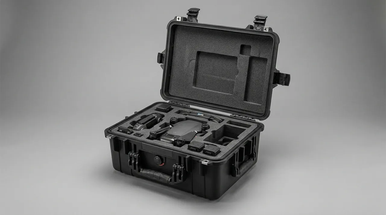
Verification Plan and Cleanliness Re-Test
Verification exists to demonstrate that a transport sequence leaves the critical performance of a dicing component unchanged. A dicing component verification plan should cover mechanical, environmental, cleanliness, and functional categories.
| Test Category | Method Family | Design Intent | Acceptance Basis | Record Kept |
|---|---|---|---|---|
| --- | --- | --- | --- | --- |
| Free-fall drop | ISTA program set with GB/T 4857 | Show the case survives a handling drop | Insert sound, spindle unmoved, blade edge intact | Drop height and orientation |
| Random vibration | ISTA program set with GB/T 4857 | Show road and rail excitation is survivable | No drift accumulation, no fastener loosening | Axis, level, duration |
| Swept-sine sweep | In-house work instruction | Confirm no resonance inside the excitation band | Response peak falls where the design predicts | Sweep rate and peak plot |
| Compression in stack | GB/T 4857 | Show stacking does not compact the insert | Insert compression inside allowance | Stack height and duration |
| Temperature and humidity | MIL-STD-810H method clauses | Show climate swings leave no damage | No dew, no rust, no mould growth | Cycle count and range |
| Reduced pressure | MIL-STD-810H method clauses | Show air freight does not deform the case | Seal undistorted, equalization open | Pressure level and hold time |
| Cleanliness after test | In-house work instruction | Show the insert still sheds nothing | Wipe and particle counts inside limits | Sampling points |
| Function after test | In-house work instruction | Show the part still meets specification | Runout, stage accuracy, imaging zero pass | Measured values |
Cleanliness re-test is the most dicing-specific item and the one most often omitted. Perform particle counting or wipe sampling on interior surfaces and component surfaces after mechanical and environmental testing, confirming the tests did not cause insert powdering or outgassing beyond limits. Once an insert has powdered, cracked, or taken a lasting compression set during the test sequence, the design must be turned down regardless of how the component fared on the shock table, since it would stop acting as a clean barrier after an actual journey.
Functional re-measurement answers the separate question of whether the component is still acceptable. Measure radial runout and axial endplay for a spindle, repeatability for a stage, and imaging center and zero position for vision and height modules. Only when functional re-measurement passes has the packaging met its purpose.
JUNZHJIA approaches a dicing component packaging program by modelling the insert from the customer's drawings, sensitivity grading, and cleanliness class, running a trial fit, keeping spindle and blade in strictly separate cases, and then setting case structure, sealing, pressure equalization, and static protection against the chosen transport mode. For spares that circulate long term, an insert inspection and replacement plan can be provided. Volume supply, OEM and ODM programs, and global delivery can be scheduled to the project's cadence, and paperwork covering materials and test records is available on request.
Frequently Asked Questions
Q: Why can a dicing spindle and a dicing blade never share the same case?
A: Because their mass and sensitivity mechanisms differ so greatly that co-packing creates two problems at once. The first is inertial loading. A dicing spindle typically weighs several kilograms to several tens of kilograms while a blade weighs from a few grams to a few tens of grams, a difference of hundreds to over a thousand times. Under transport shock the spindle generates inertial loads far beyond what a blade can withstand, so even occasional contact makes blade damage nearly certain. The second is surface damage. A blade edge is sintered from diamond abrasive and bond, so it is extremely hard, and its sharp edge scores the mating face of the spindle flange. That flange face determines spindle assembly accuracy, and once scored it must be reground. There is also an assembly-sequence reason: after a spindle is mounted it must go through running-in and rotation accuracy confirmation, and installing a blade before that is complete serves no purpose. Separate packaging therefore supports dispatch in assembly order and keeps blades out of the cutting-zone environment during installation.
Q: Why does an air-static spindle demand higher cleanliness than a rolling-bearing spindle?
A: Because its load-carrying mechanism depends on a micron-scale air film gap, and that gap is extremely contamination-sensitive. An air-static spindle supplies gas through restrictor orifices to form a load-bearing film in the bearing clearance, typically only a few microns thick. At that scale, a single particle larger than the gap can cause a local pressure anomaly that shifts the vibration signature or degrades rotation accuracy, and the small restrictor orifices can be locally blocked by a particle. A rolling-bearing spindle, by contrast, fails mainly through raceway indentation and preload change, so it tolerates particles somewhat better but is more shock-sensitive. Air-static spindle packaging must therefore make internal cleanliness the primary objective: cleanroom plugs in every air port, the whole spindle sealed in a cleanroom bag, and no shedding material anywhere in the case. Rolling-bearing spindle packaging should focus more on shock limits and cushion design. Both demand higher cleanliness than an ordinary machine tool spindle.
Q: Why must ultra-thin blades never be stacked in packaging?
A: Because stacking makes the lower blade carry the weight above for an extended period. Ultra-thin blades are tens of microns thick with low compressive and bending capacity, so sustained load produces permanent distortion, and the direct consequence is increased outer diameter runout and kerf offset. Even without an obvious impact, several days under static load can cause irreversible deformation. The correct approach is to carry each blade in its own cradle or division, with a low-shedding soft contact material on the cradle, positioned away from the edge region, and space left near the edge so no hard contact is possible in any direction. Beyond loading, stacking also risks edges scoring each other, and once an edge chips, cutting capability drops while the dislodged diamond abrasive becomes a contamination source that scores the wafer surface. Blade packaging therefore follows individual support and zero hard contact as the first principle, with moisture and corrosion control as the second.
Q: Why is vapor-phase corrosion protection better than anti-rust oil for blades?
A: Because the negative effects of oil appear during use, where the cost in a clean environment is high. The traditional method coats metal with an oil film that isolates water and oxygen, but a blade edge is a porous composite of diamond abrasive and bond, so oil penetrates the bond surface. After installation, that residue changes how coolant distributes across the edge and the cutting zone, causing local under-cooling and thermal damage. The oil film is also a contamination source in a clean environment, depositing on optical parts and inside spindle clearances. Vapor-phase protection works differently: the inhibitor material releases corrosion-inhibiting molecules into a closed space that form a molecular-level adsorbed layer on metal surfaces, leaving no liquid residue. It performs best combined with a dry environment, which is why the standard combination is vapor-phase inhibitor material plus controlled dryness plus a humidity indicator card. Note that vapor-phase protection requires a relatively closed space and its effect ends when the case is opened, so it suits transport only. Components stored long term belong in a dry cabinet or controlled environment.
Q: Why does thin-wall blade cover packaging invert the logic used for heavy structural parts?
A: Because the failure mechanisms are opposite. A thin-wall blade cover fails by being dented or bent, meaning buckling under external pressure, so the correct approach is internal support: place support inside the cover along the load direction so shock travels through the support structure and the thin wall itself does not carry bending. Wrapping and compressing from outside, as one would for a heavy part, makes a thin-wall part dent more easily. A heavy structural part is different: it is stiff enough not to distort under external wrapping, so its packaging focus is limiting displacement and spreading shock, and external conforming support achieves that. This difference causes frequent errors in practice, because thin-wall and heavy parts often share a case and operators naturally apply the same wrap-and-compress method to both. Classify components by buckling resistance rather than by weight, and treat thin-wall, hollow, and frame-type parts as internal-support cases.
Q: Why do dicing motion stages need transport blocks?
A: Because a moving part cannot be reliably held in a defined position by friction alone. Transport vibration is continuous and multi-directional, and friction restraint gradually slips under repeated excitation, with a slip amount that cannot be predicted and cannot be judged from appearance on arrival. A rigid transport block mechanically locks the moving part to a defined position, so the displacement is known at the design stage and can be verified on arrival by checking whether the block is still in place. Three points govern their use: blocks must be removable with clear marking and a defined removal sequence; they must appear as separate line items on the packing list and be checked off; and no drive force may be applied to a motion axis before its block is removed, since that risks secondary damage. For heavy stages, the case should also spell out its lift points and load-bearing structure, so that tines never end up under a random part of the base and the load never travels into the stage.
Q: Why must cleanliness re-test follow mechanical testing rather than precede it?
A: Because mechanical testing itself can change the cleanliness performance of the packaging, and that change is only detectable by testing afterwards. During drop, vibration, and compression tests, the insert undergoes compression, shear, and impact that can produce microcracks, surface powdering, or edge fracture. For open-cell foams, exposed cross-sections after testing release markedly more debris; for outgassing-sensitive materials, compression accelerates volatile release. Testing cleanliness only before mechanical testing gives the performance of a new package, whereas the customer actually uses a package that has already been through vibration, and the two are not equivalent. The correct sequence is to complete mechanical and environmental testing first, then perform particle counting or wipe sampling on interior and component surfaces to confirm nothing exceeds limits, while also inspecting the insert for powdering, cracking, or significant compression set. If the insert has lost its ability to serve as a cleanliness barrier, the design should not be accepted even if the component passed the shock test.
Q: How should dicing equipment component cases interface with the wafer carrier management system?
A: The existing carrier management logic can be reused at four levels. First, exterior surface standard: carriers interface with equipment load ports under defined exterior cleanliness and dimensional requirements, and a manually handled component case should match that exterior cleanliness standard so it does not become a contamination source. Second, handling method: if cases and carriers circulate in the same area, handling tools and routes should be shared where possible, and case dimensions and weight should suit tools already on site, reducing the overhead of dedicated equipment. Third, identification system: carriers normally carry unique identifiers and traceability records, and enrolling component cases in the same system makes it possible to trace which component was in which case, when it was opened, and who removed the protective items, which is valuable in quality investigations. Fourth, opening area: unpacking component cases in the same area used for carriers lets cleanliness control, static protection, and personnel management be reused rather than duplicated. Compared with wafer cases, component cases share the same cleanliness and static control system but require higher mechanical protection.
Conclusion and Related Reading
What makes a wafer dicing equipment component case hard to design is that it faces three protection targets of entirely different natures: a high-speed precision spindle, a brittle blade only tens of microns thick, and optical and fluid components that demand ultra-clean handling. These three share almost no protection parameters in common, and forcing one scheme to cover all of them guarantees that one category is sacrificed. The first principle this article returns to is therefore separation: spindles and blades in separate cases, optical parts and metal parts in separate cavities, elastic parts and rigid parts in separate zones. The second principle is to treat cleanliness as a hard constraint that cannot be relaxed, because mechanical parameters can be compensated with more cushioning while compromised cleanliness usually costs more to restore than to re-source. The third principle is that verification must include functional re-measurement and cleanliness re-test, because dicing components fail through accuracy degradation rather than visible damage. For a fab equipment engineer, writing those three principles into a purchase specification is more effective than specifying materials item by item. For tool builders and spare parts suppliers, a packaging design that withstands re-measurement is among the most effective ways to cut overseas after-sales cost.
Related Reading