

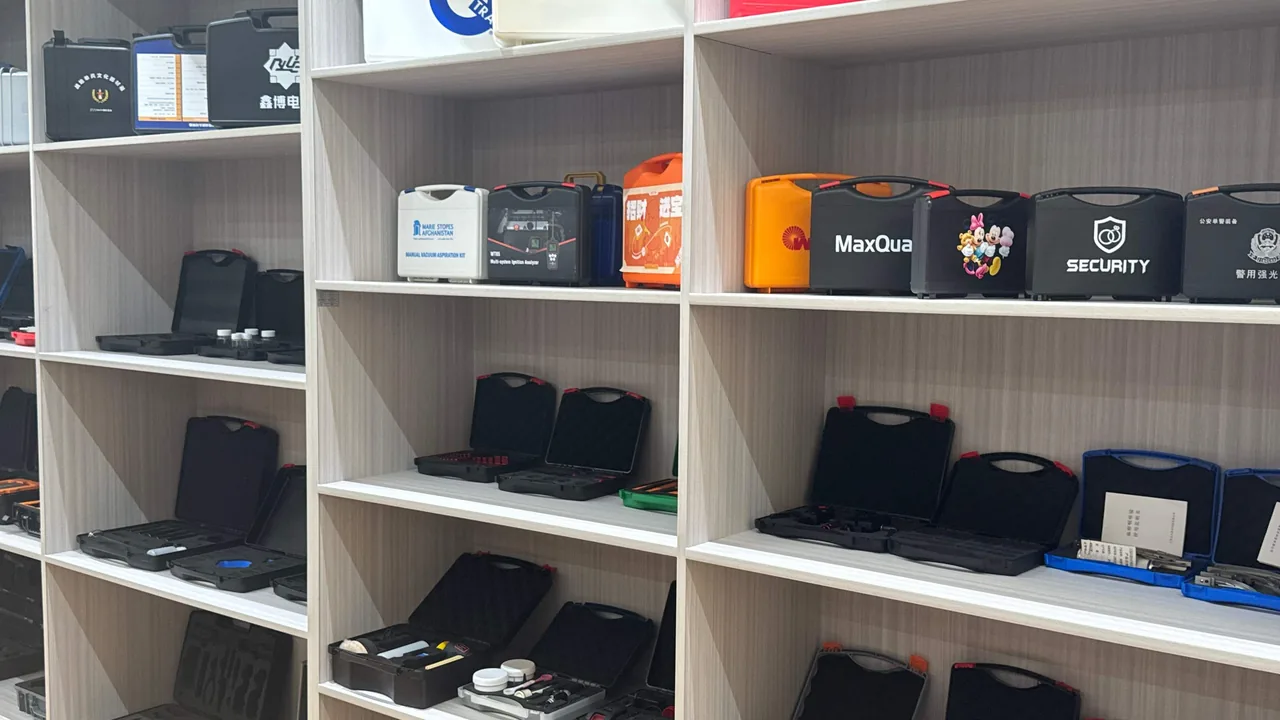
Field inspection of wind turbine blades is, in essence, the practice of carrying a set of high-precision instruments into an environment that is fundamentally hostile to precision instruments. The blade root sits inside the tower, where space is tight and dust coexists with condensation. The outer blade surface is exposed to day-night temperature swings, ultraviolet radiation, and the steady attack of sea mist and salt. Borescope insertion tubes, ultrasonic phased-array probe wedges and arrays, couplant, encoder cabling, and drone inspection payloads all travel from the warehouse to the work site and back, passing through highway vibration, nacelle lifting, ladder carrying, and rain-forced shutdowns along the way. A single water ingress, dust intrusion, or drop can waste an entire shutdown window.
Protection principle: wind blade inspection equipment must follow a one-case-per-instrument rule where the case opens ready to use and closes sealed the moment work stops. JUNZHIJIA builds custom compartmented liners and stable sealing levels around each instrument outline so that water, dust, temperature, and vibration are all held outside the case during transport and operation, rather than remedied after a failure occurs. The JUNZHIJIA wind blade inspection case family is designed around the field rhythm of four core item groups: the borescope main unit, the phased-array acquisition unit, the probe set, and the drone payload.
Table of Contents
- Field Conditions and Equipment Risks at Wind Blade Inspection Sites
- Inspection Equipment Inventory and a Protection Requirement Matrix
- Housing Materials and Structure: PC, ABS, Rotomolded and Stainless Steel
- Sealing Ratings: What IP65 and IP67 Actually Mean Inside a Nacelle
- Rain, Moisture and Condensation Control in Three Layers
- Temperature Range: Low-Temperature Brittleness, Heat Softening and UV Aging
- Dust, Salt Spray and Corrosion at Coastal Wind Farms
- Shock, Vibration and Transport Drop: From Package to Instrument
- Foam Liners and Compartment Design: By Outline, Not by Dimensions
- Packing Drone Inspection Payloads and Rope-Access Gear
- Field Workflow: Opening, Assembling, Resetting and Counting
- Stacking, Transport and Storage Load Planning
- Customization, Tooling, OEM/ODM and Incoming Acceptance Criteria
- Frequently Asked Questions FAQ
- Conclusion and Related Reading
Field Conditions and Equipment Risks at Wind Blade Inspection Sites
Onshore and offshore wind farms present very different working conditions, yet the categories of risk are shared. Internal blade inspection normally begins at the blade root manhole. The opening is small, and the technician crawls in carrying a strap-mounted borescope unit and lighting power supply. The case itself often stays on the nacelle platform or at the tower base while the instrument sits partly exposed in a carry bag. External blade inspection relies on rope access, aerial work platforms, or drones flying close to the surface. Ultrasonic phased-array scanning requires the probe to be moved chordwise in small steps, with couplant, marker pens, and encoder cabling repeatedly picked up and set down on the blade surface.
The risks fall into four groups. The first is water: rainfall, sea mist, condensation, and wash-down spray. Condensation is the most insidious of these, because an instrument brought from a cold night environment into a warm daytime nacelle can experience a surface temperature difference of more than ten degrees Celsius, causing moisture to deposit directly on cold surfaces. The second is dust and particulates. Blade sanding dust, grit, and fiber debris enter connectors and cooling vents, and the damage to optical surfaces and cooling fans is irreversible. The third is temperature. Blade interiors at northern wind farms can fall below minus twenty degrees Celsius in winter, while nacelle interiors under direct summer sun can exceed sixty degrees, well outside the comfortable operating band of most electronic instruments. The fourth is mechanical shock and vibration: the road spectrum during highway transport, swaying during lifting, and knocks during temporary on-site storage are all transmitted through the case to the equipment inside.
These four risk groups are not independent. Low temperature reduces the elasticity of gaskets, and sealing performance falls with it. High temperature accelerates foam softening and adhesive creep, so liner positioning accuracy degrades. Salt spray corrodes latches and hinges, making the case harder to open and close. Case selection must therefore be evaluated against the combined environment rather than a single metric, which is the main difference between a wind farm scenario and a conventional laboratory scenario.
Inspection Equipment Inventory and a Protection Requirement Matrix
Listing the equipment commonly used for wind blade inspection and mapping each item to its protection priorities produces a clear requirement matrix. This table becomes the basis for case, liner, and sealing level selection.
| Equipment category | Typical form and weak points | Main protection priorities | Suggested sealing and cushioning |
|---|---|---|---|
| --- | --- | --- | --- |
| Borescope main unit | Display, insertion tube port, battery bay | Drop resistance, rain, dust-blocked ports | IP65 or better, PE base plus compartments |
| Insertion tube and tip | Long flexible tube, optics and light guide | Crush, kink and abrasion resistance | Curved channel plus soft EVA collar |
| Phased-array acquisition unit | Multi-channel connectors, cooling vents | Moisture, vibration, connector strain | IP67, custom EVA cavity |
| Phased-array probe and wedge | Array face, wedge coupling face | Impact and abrasive contamination | Separate recess plus cover plate |
| Couplant and consumables | Bottles and tubes | Leak and inversion resistance | Upright slot plus drip tray |
| Encoder and cabling | Long cable runs, circular connectors | Tangling and connector strain | Cable spool position plus plug cradle |
| Drone inspection payload | Gimbal camera, lidar | Vibration, dust, lens scratching | High-density EVA plus damped suspension |
| Rope-access and safety gear | Rope, hardware, harness | Moisture and metal corrosion | Breathable mesh bag plus separate cavity |
| Spare power and chargers | Lithium packs, adapters | Short circuit, impact, fire | Thermal barrier cell plus separate retention |
| Records and calibration tools | Calibration blocks, recording terminal | Loss, impact, moisture | Small compartments plus desiccant |
The matrix shows that one case often has to hold items that fear water, dust, vibration, and temperature simultaneously, and their needs do not agree. A borescope main unit fears drops but tolerates light humidity; a phased-array probe fears impact but tolerates rainfall; lithium packs fear heat and must not be mixed with metal tools. This is why the one-case-per-instrument compartment philosophy exists. Rather than piling instruments into one general-purpose case, equipment is grouped and each group is isolated in its own cavity.
For teams working across consecutive wind farms, a typical configuration is one main unit case, one probe and cable case, one consumables and tool case, and several carry bags. The main unit case handles electronic protection, the probe case handles precision mechanical parts, and the consumables case holds couplant, marker pens, and desiccant. All three can be stacked for transport using a unified case type and stacking structure. Teams that also cover substations and collector lines may follow the approach described in Power Inspection Equipment Cases and manage general meters and blade inspection gear in separate cases, so that the protection level of one category never has to be compromised for the other.

Housing Materials and Structure: PC, ABS, Rotomolded and Stainless Steel
The shell material of a wind blade inspection case directly determines cost, weight, and service life. The trade-offs among the four mainstream options are as follows.
Engineering plastic injection-molded cases are mainly made of PC or PC/ABS alloy, with wall thickness typically between two and four millimeters and ribbed reinforcement in the shell. Tensile and impact performance is good, self-weight is low, and the format suits a borescope main unit case that must be hand-carried and hauled up ladders. PC offers better low-temperature toughness than ordinary ABS and retains some impact resistance at minus twenty degrees Celsius, but long-term ultraviolet exposure brings yellowing and surface chalking that must be watched.
Rotomolded cases are produced in a single rotationally molded pass from LLDPE or cross-linked PE. Wall thickness is large, the body has no seams, impact and compression resistance are strong, and very large sizes are feasible, which suits whole-unit transport. The drawbacks are higher self-weight, lower dimensional accuracy than injection molding, and the need to fasten liners separately. For situations requiring crane lifting of the whole case or air transport alongside the equipment, the rotomolded option is more dependable.
Stainless steel or aluminum cases excel in strength and corrosion resistance and suit fixed storage that stays on site and is exposed to salt spray for long periods. They are heavy and costly, and metal shells behave differently from instruments during condensation, so an insulating liner is required.
PP housings are inexpensive and chemically resistant, but markedly brittle at low temperature and not recommended as the primary housing for northern winter work at height.
Structural detail matters just as much. Side-wall ribs, a double-wall lid, inset hinges, and over-center self-locking latches all influence deformation and sealing after long service. For wind farm use, prefer a case with an integrally molded handle or with wheels and a telescopic handle, because the walk from the vehicle to the tower base is often hundreds of meters over gravel or grass, and carrying a case by hand is the norm.
Sealing Ratings: What IP65 and IP67 Actually Mean Inside a Nacelle
Ingress protection ratings are defined by IEC 60529 and its national counterpart GB/T 4208. The first digit after IP denotes protection against solid foreign objects and dust, and the second denotes protection against water. A first digit of 6 means dust-tight, and water digits range from 5 for water jets to 7 for temporary immersion.
In wind blade inspection, rating selection must distinguish where the equipment is used. The tower base and nacelle platform are usually sheltered, where wind-driven rain and condensation are the main threats and IP65 is sufficient. External blade work, rope-access points, and drone launch and recovery areas are fully exposed, and equipment may be set down on the blade surface or briefly on grass and gravel with standing water present, which calls for IP67. It is important to note that IP67 temporary immersion is conditional. The standard specifies a particular depth and duration and assumes an undamaged sealing surface and fully closed latches.
Real sealing performance depends on three elements. The first is gasket material: silicone tolerates a wide temperature range and recovers well, EPDM offers excellent weather and ozone resistance, and nitrile resists oil but has modest weathering performance. The second is groove geometry: whether the groove cross-section matches the gasket and whether compression stays within the design window. The third is latch count and distribution. If there is no latch at the midpoint of a long side, the lid can bow under load and a gap opens along the sealing surface. Many cases sold as IP67 that nevertheless leak trace back not to the gasket itself but to excessive latch spacing or insufficient wall thickness.
Rain, Moisture and Condensation Control in Three Layers
Moisture control at a wind farm cannot rely on the gasket alone. Three layers must work together.
The first layer is isolation. Case sealing keeps external liquid water and spray out, and this is the foundation. The rating should be chosen according to where the equipment will be exposed, not according to which number is higher.
The second layer is internal humidity management. Even with perfect sealing, the air trapped at closing time contains moisture, and that moisture condenses on cold surfaces as the temperature falls. Practical measures include placing reusable desiccant inside with a humidity indicator card, closing the case in a dry and thermally stable environment, and choosing a case with a pressure equalization valve whose hydrophobic membrane slowly balances the pressure difference so the gasket is neither forced open nor able to draw in damp air.
The third layer is recovery and regeneration. After every opening, wipe the shell and the gasket groove, check the sealing surface for grit and scratches, then replace or regenerate the desiccant before closing. If water has entered, remove all liner sections and instruments, air dry or use gentle low-temperature drying, and never bake EVA or PE liners at high temperature, which causes shrinkage and distortion.
These three layers align with the practice described in Outdoor Case Rain and Humidity Design for rainy-season work, with the added wind farm factors of rapid temperature change inside the nacelle and altitude-driven pressure differences.
The value of a pressure equalization valve is easily underestimated in wind farm work. Cases are frequently moved from low-altitude warehouses to higher mountain sites, or transported by air through alternating hot and cold conditions. The resulting pressure difference makes lids hard to open and accelerates gasket fatigue. A valve-equipped design noticeably improves both opening feel and gasket life.
Temperature Range: Low-Temperature Brittleness, Heat Softening and UV Aging
Temperature is the long-term variable that wind blade inspection equipment must live with. Blade interiors at northern sites can reach minus twenty-five degrees Celsius in winter, nacelle interiors under direct sun can exceed sixty degrees in summer, and ultraviolet intensity on the outer blade surface is far above ground level.
The main effect of low temperature is embrittlement. Ordinary ABS loses impact strength noticeably around minus twenty degrees, foam hardens and its cushioning capacity falls, and gaskets lose elasticity so sealing degrades. Selecting PC/ABS alloy, modified low-temperature formulations, and EVA foam that stays flexible in the cold is the mitigation.
The main effect of high temperature is softening and creep. Shell rigidity falls, so deformation is more likely under stacking; softened foam widens the locating channels and lets equipment move inside; adhesives can bleed or debond under prolonged heat. Choose materials whose rated range covers minus thirty to seventy degrees Celsius, and verify with thermal cycling.
Ultraviolet exposure mainly affects case surfaces and rubber parts. Cases parked outdoors for long periods chalk, discolor, and embrittle, and gaskets age and crack. Formulations with UV stabilizers, or a simple shade cover during storage, extend service life. For equipment that must remain outdoors, pair the case with a field cabinet that has a sunshade top.
Dust, Salt Spray and Corrosion at Coastal Wind Farms
Air at offshore and coastal onshore wind farms carries a high salt load, and metal parts corrode far faster than inland. Blade sanding dust is both abrasive and hygroscopic, and once it settles in a sealing groove it becomes a path for water ingress.
| Environmental factor | Effect on case and equipment | Mitigation |
|---|---|---|
| --- | --- | --- |
| Chloride salt spray | Latches, hinges and screws corrode; opening becomes difficult | Stainless hardware, plated finishes, periodic fresh-water rinse |
| Blade sanding dust | Abrades sealing surfaces, clogs ports and vents | Regular groove cleaning, port dust caps |
| Sea mist and high humidity | Internal condensation, damp circuit boards | Desiccant, equalization valve, higher sealing rating |
| Blowing sand | Enters latch mechanisms, wears sliding surfaces | Dust-resistant geometry, sheltered storage |
| Day-night temperature swing | Internal pressure cycling, gasket fatigue | Pressure equalization valve, correct gasket selection |
Salt spray testing usually follows GB/T 10125, subjecting the case and hardware to a neutral salt spray test to evaluate corrosion resistance over a defined concentration and temperature. During selection, ask the supplier for salt spray records for the hardware and judge against the actual inspection cycle whether higher-grade stainless parts are needed.
In practice, salt spray performance and sealing performance are not the same thing. A case with a high sealing rating but ordinary hardware treatment may keep its seal intact in a coastal environment while the latches seize and refuse to open. For coastal users, hardware corrosion resistance deserves the same weight as the sealing rating in the purchasing specification.
Shock, Vibration and Transport Drop: From Package to Instrument
Mechanical risk in transport falls into two categories: low-frequency, high-amplitude drops and impacts, and continuous high-frequency vibration. Transport testing of packages commonly follows the GB/T 4857 series, the ISTA series, and ASTM D4169. The core logic of these standards is to simulate real distribution hazards and thereby verify how well the package protects its contents.
Drop performance depends strongly on weight, attitude, and cushion thickness. The drop height a case can survive is not the drop height the instrument can survive, because impact travels through the case and liner to the equipment. Design should set the allowable drop height from the cushioning stroke of the liner, not from a marketing claim that the case survives a one-meter drop.
The main hazards of vibration are resonance and loosening. When the vehicle vibration spectrum approaches the natural frequency of the case or the instrument, amplitude is amplified, leading to loosened screws, worn connectors, and displaced optical parts. If the array and wedge of a phased-array probe develop even slight play, coupling quality and signal integrity suffer directly. Liner design should therefore hold the instrument in a state of moderate clamping without over-compression, avoiding both rattle and long-term preload that fatigues the structure.
A practical rule for inspection teams: during transport, place the main unit case and probe case near the middle of the vehicle, away from the rear where bounce is greatest, and avoid stacking them directly against generators, tool chests, and other heavy items. After every long trip, inspect the exterior, latches, and sealing groove first, then power up and run a self-test. Where borescope and phased-array units share a case, the damping requirements follow the same practice used for Industrial Detection Cases, and the cushioning stroke figures from that reference can be used to set the drop acceptance height.
Foam Liners and Compartment Design: By Outline, Not by Dimensions
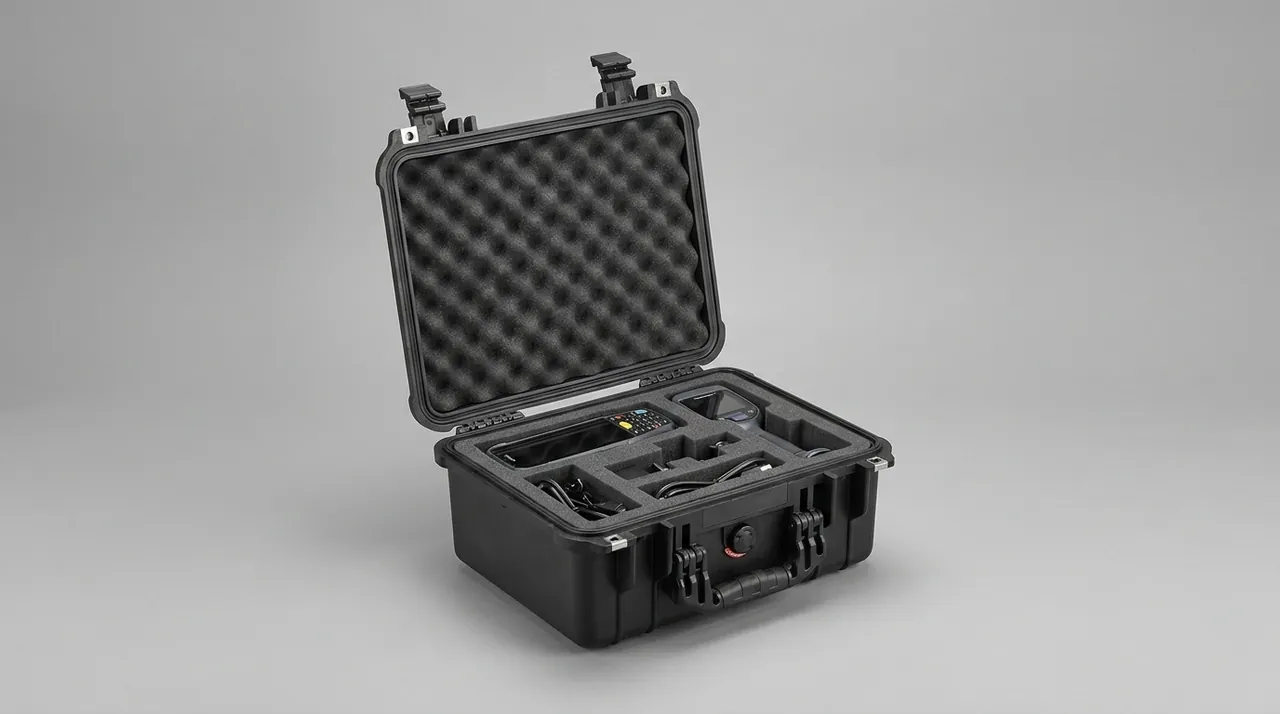
The liner is what turns a protective case from a shell into a protection system. A square cutout sized only to length, width, and height still lets the instrument move, and impact travels straight to the equipment during a drop. The correct approach is a cavity that follows the instrument outline while controlling clamping force.
The trade-offs among common foam materials are as follows. EPE pearl foam is inexpensive and light with moderate resilience, suited to filling and padding. EVA foam is dense, resilient, and resistant to repeated compression without collapsing, suited to supporting and locating precision equipment. PE foam is harder and load-bearing, suited to the base cushion of long, heavy items. IXPE cross-linked foam is thin and dense, suited to thin cushioning layers and surface facing.
Compartment design should follow several principles. First, place heavy items low in the case or near the hinge side, so the center of gravity does not rise when the lid opens and tip the case over. Second, use curved or coiled channels for long slender items such as insertion tubes and ultrasonic cabling, preventing bends tighter than the minimum bend radius. Third, give liquid consumables their own cavity with a cover so leakage cannot contaminate other equipment. Fourth, separate precision parts from metal tools to avoid mutual impact and galvanic corrosion. Fifth, reserve dedicated positions for desiccant and humidity indicator cards so they never touch the instruments directly.
For equipment that is used frequently on site, cut finger notches along the cavity edge so the item can be lifted out one-handed even with gloves on. Anti-slip gloves are standard at wind farms, and finger notches should be at least thirty millimeters wide. For items such as drone payloads that are mounted and removed repeatedly, a quick-release base can be combined with the liner so the payload is located the moment it enters the case and ready to fly the moment it leaves. The practice of grading foam density and compression by instrument weight is described in more detail in Field Inspection Equipment Cases, and can be applied item by item to set support and cushion thickness.
Packing Drone Inspection Payloads and Rope-Access Gear
Drone-based blade inspection has become routine, and payloads include visible-light gimbal cameras, thermal imagers, lidar, and high-resolution lenses. What these payloads share is a precious optical surface, a fragile gimbal mechanism, and sensitivity to vibration. When packing, use a layout in which the lens faces upward, the gimbal is locked, and the airframe is suspended. Build a wrapping EVA cavity and set a damping pad at the cavity floor so transport vibration is not transmitted directly into the gimbal motors.
Rope-access gear includes static rope, harness, descender, carabiners, pulleys, and rope protectors. This gear is bulky, heavy, moisture-sensitive, and vulnerable to sharp contact. Pack it in a separate breathable cavity or mesh bag so residual moisture can evaporate. Separate metal items with soft dividers to prevent rubbing that raises burrs. Coil the rope and secure it on a dedicated hook so it cannot tangle with the hardware.
The two categories can share one large case, but they must occupy separate compartments that never touch. If they do share a case, install a removable internal divider so the case can switch between a payload-plus-rope configuration and a payload-plus-spares configuration. For remote mountain sites reached on foot, consider putting the rope-access gear in a backpack-style soft bag and leaving the payload in the hard case for vehicle transport.
Field Workflow: Opening, Assembling, Resetting and Counting
A disciplined opening and reset routine significantly reduces equipment attrition. Open and self-check at the inspection vehicle or the site staging area rather than improvising at the tower base.
The recommended sequence is as follows. First, lay the case flat in a dry, sheltered staging area, check the shell and latches for damage, and record the seal number and tag. Second, photograph the internal layout before removing anything, so items can be returned to their correct positions. Third, remove items one by one against the checklist and record battery state and calibration status. Fourth, return lids and liner cover plates to the case or to a designated spot so nothing is left on the blade surface or in the nacelle. Fifth, after work is complete, clean, dry, reset, and count everything in the staging area, and confirm nothing is missing before closing the case.
Counting is best supported by an in-case checklist card and QR asset labels. JUNZHIJIA custom cases can be specified with a label recess in the liner or lid for the equipment list, calibration expiry, and responsible person. When a case is handed to another crew, the contents can then be confirmed quickly.
Stacking, Transport and Storage Load Planning
Stacking load is a long-neglected specification. Cases stored in a warehouse are stacked for months, so the bottom case bears the weight of everything above it. Inside a truck, cases also bear dynamic loads from acceleration and braking. Stacking design must account for both static and dynamic load.
A practical approach is to confirm the loaded weight of a single case, then determine the number of tiers from the rack or truck interior height. Because a lid is usually weaker than a base, place heavy cases at the bottom and light cases on top, and never stack a rope-access gear case above a drone payload case. For long journeys, strap the whole stack so it cannot slide forward under braking, and place anti-slip pads between cases to prevent creep and abrasion.
The storage environment matters equally. Keep the warehouse dry and ventilated, and avoid leaving cases in contact with the floor for long periods. Do not store cases in direct sunlight, which causes UV aging. Confirm the interior is dry and replace desiccant before closing. For cases not in use for a long time, leave the latches open so the gasket is not permanently compressed and deformed. For wheeled and telescopic-handle models, avoid storing them with load resting on the wheels, which flattens the wheel faces.
Customization, Tooling, OEM/ODM and Incoming Acceptance Criteria
Wind blade inspection equipment is updated frequently, and new models, payloads, and probe sets change dimensions and layout regularly. General-purpose cases rarely satisfy fit, access, and stacking requirements at the same time, so customization becomes the mainstream choice. Customization usually has three levels: liner-level cutting to an existing case type, which is fastest and least expensive; case-level changes to dimensions, latches, handles, and colors, which requires new tooling; and system-level design that combines case, liner, labels, and accompanying documents, which suits standardizing an entire inspection team.
When choosing an OEM or ODM partner, the technical agreement should state the following: material grade and flame retardancy requirements, sealing rating and test method, hardware material and corrosion grade, liner material density and tolerance, case dimensional tolerances, stacking load requirement, printed content and position, accompanying documents such as the certificate of conformity, test report, packing list, and operation and maintenance manual, and the first-article acceptance criteria. First-article acceptance should cover appearance, dimensions, sealing, latch cycle life, drop, and stacking, and production batches should be rechecked against a sampling plan.
This case family is manufactured by Kexin New Materials (Guangdong) Co., Ltd., which can provide an integrated service from liner design through tooling and sampling to volume delivery based on a team's actual equipment list, and can print team numbers, equipment lists, and warning marks on the case and liner. For projects that interface with international inspection bodies, turbine OEMs, or wind farm owners, confirm the language versions and compliance statements required for the accompanying documents at the purchasing stage. Where structure is more complex and tolerances are tighter, such as a borescope main unit case, the fit between liner and shell can follow the tolerance and clamping recommendations in Precision Instrument Protective Case Design.
On arrival, verify each case against the following criteria: no visible deformation or scratches; latches operating smoothly and symmetrically; gasket seated correctly without twisting; no visible gap with the lid closed; marking and printing consistent with the order; liner cavity dimensions matching the measured equipment; and complete accompanying documents. If sealing performance is disputed, confirm it by an air-tightness hold test or a spray test.
Frequently Asked Questions FAQ
Q: Why can't wind blade inspection cases be selected by outer dimensions alone, and what does a custom liner actually add?
A: Outer dimensions only answer whether the equipment fits; the liner answers whether it stays fixed. Within a wind blade inspection kit, the borescope main unit and phased-array acquisition unit are electronics, probes and wedges are precision mechanical parts, and insertion tubes are long flexible items, and each requires a completely different retention method. A cavity cut only as a rectangular void lets equipment move continuously under transport vibration, and protruding parts are damaged first. During a drop, impact travels directly through the base with almost no cushioning stroke. A liner cut to the outline supports the item at multiple contact points, absorbs impact energy through foam compression, and confines the insertion tube above its minimum bend radius. More practically, a custom liner enforces a fixed position for every item, so any operator can return it correctly and no lens is scratched or probe dropped through careless placement. Verify the finished liner by measuring the gap between the cavity wall and the instrument surface, which should stay within two to three millimeters, and confirm it with a loaded drop test at the agreed height.
Q: How should IP65 and IP67 be chosen for wind farm work, and is a higher rating always better?
A: Higher is not automatically better; choose by the exposure point of the equipment. The tower base and nacelle platform are sheltered, where the main threats are wind-driven rain, condensation, and dust, so IP65 is sufficient. External blade work, rope-access points, and drone launch areas are fully exposed, and equipment may be set down on the blade surface or on grass with standing water, which calls for IP67. A higher rating usually means heavier latch structure, greater gasket compression, and harder opening, and if the equipment is never exposed to standing water this simply adds operating burden. What actually determines real water resistance is not the nominal rating but whether groove geometry, gasket material, and latch distribution match. Set the sealing rating, the test method, and the hardware corrosion requirement together in the purchasing specification, and decide case by case against the real exposure scenario. For nacelle use, specify the gasket in silicone or EPDM, and check that latches are spaced no more than three hundred millimeters apart along the long sides.
Q: Condensation appears inside the case even though there is no obvious water ingress. What causes it, and how is it solved?
A: This is usually not external seepage but moisture sealed in at closing time that deposits as the temperature falls. Wind farms have large day-night temperature swings, and after the case cools overnight the internal moisture condenses on metal and optical surfaces. There are three layers of remedy. First, make sure the case and equipment are dry before closing, and work in a thermally stable indoor or sheltered staging area wherever possible. Second, place reusable desiccant inside with a humidity indicator card and replace or regenerate it on a schedule. Third, choose a case with a pressure equalization valve, whose hydrophobic membrane balances the internal and external pressure and reduces the chance that the gasket is forced open and draws in damp outside air. If condensation has already appeared, remove all liner sections and instruments and dry them in moving air, avoiding high-temperature baking, which shrinks and distorts the liner. Note also that desiccant saturation depends on how often the case is opened: a case opened twice a day on a two-week campaign needs a larger charge than one opened weekly.
Q: What are the most common failure modes of an ultrasonic phased-array probe in transport, and how does the liner address them?
A: The most common are array-face impact, wear of the wedge coupling face, and cable connector strain. Once the array face is scratched or dented, coupling consistency falls, which shows up as unstable signals and degraded imaging. Wear on the wedge coupling face changes the beam entry angle and affects defect positioning. If the cable connector is repeatedly pulled during transport, internal solder joints fatigue. Targeted design measures include a separate recess with a cover plate for the probe body so it never contacts other equipment, a soft EVA slot for the wedge so its coupling face never rests against a hard surface, and a cable spool that limits the run to the minimum bend radius together with a dedicated plug cradle that carries the load so pulling force never reaches the connector body. After each trip, perform an external inspection and a power-on self-test. Record the probe serial number and coupling check result on the same sheet, because a probe that fails after a specific trip is easier to trace when a transport log exists.
Q: Why does packing a drone inspection payload emphasize locking the gimbal and suspending the airframe?
A: Because a gimbal is a multi-axis mechanism, and its motors and reduction stages are most vulnerable to sustained vibration and external twisting when unpowered. If the payload is rigidly supported inside the case, the airframe weight and vibration act repeatedly on the gimbal joints, and over time this increases play, causes zero-point drift, and can even damage the motors. The correct method is to lock the gimbal with the original transport lock before packing so it is in its travel position, build a wrapping cavity so the airframe is supported by foam as a whole rather than through the gimbal, place a damping pad at the cavity floor to isolate vehicle floor vibration, and orient the lens upward with a safe clearance so it never contacts the lid or liner. For high-value payloads, add a shock indicator label inside the liner to make abnormal impacts traceable. Mark the transport lock position with a visible tag, since the most common operator error is forgetting to lock the gimbal before the payload returns to the case after a flight.
Q: How should case hardware be protected against rust at coastal wind farms, and is good sealing enough?
A: No, sealing is not enough. Salt spray mainly corrodes metal parts such as latches, hinges, screws, and telescopic handles, and sealing performance and hardware corrosion resistance are two independent performance lines. No matter how good the seal is, a seized latch makes the case impossible to open and disrupts the whole inspection window. Coastal cases should use stainless steel hardware or a dependable plated finish, and the supplier should be asked for neutral salt spray records with the test conditions and duration confirmed against the GB/T 10125 method. In daily use, rinse the shell and hardware with fresh water after each job and dry them before storage so salt does not remain on the surface. Cases stationed on site for long periods should have a sun and rain cover, and hinge and latch pivot points should be lubricated on a maintenance schedule. Specify the torque and thread treatment for every stainless fastener too, because stainless-on-stainless threads gall, and a latch screw seized by galling is as immobilizing as one seized by rust.
Q: Which transport tests should a wind blade inspection case undergo, and what value do those reports have for purchasing decisions?
A: Common tests include drop, vibration, stacking, and compression tests per the GB/T 4857 series, the ISTA series, and ASTM D4169, plus spray and immersion tests for sealing performance. Their value lies in converting a claim about how much impact an empty case can survive into evidence about whether a package containing the specified equipment still protects its contents in a simulated distribution environment. When purchasing, check whether the test article was an empty case or a fully configured one, and whether cushion thickness, drop attitude, and drop count match actual transport conditions. For wind farm use, low-frequency vibration and dynamic stacking load also matter. Reports should also identify the testing laboratory and the date of the test. Test reports can serve as an annex to the technical agreement and as one basis for first-article acceptance and batch sampling, though they should not be the only criterion. Ask as well for the drop height and number of drops in the report, and for vibration request the axis directions and test duration so the data can be compared with the actual route.
Q: As an inspection team grows, how can case configuration improve equipment management and handover efficiency?
A: The core idea is to move equipment management from human memory into a physical constraint formed by the case and its labels. First, deliver cases as fixed kits, where each case corresponds to one equipment list, with item names and quantities printed inside and a unique storage position for every item, so mixed loading is avoided. Second, assign a QR asset number to each case and critical instrument, and register movements by scanning at check-in and check-out so handover can be verified against the list. Third, provide a label recess inside the lid for calibration expiry and the responsible person, keeping status information with the case as it travels. Fourth, standardize case type and stacking geometry so cases from different crews stack interchangeably for consolidated transport. Finally, include a maintenance schedule fixing service intervals for gaskets, desiccant, foam, and hardware, so staffing changes never create management gaps.
Conclusion and Related Reading
Wind blade inspection succeeds only if instruments survive the journey. JUNZHIJIA builds custom compartmented cases and liners that absorb water, dust, temperature, and vibration, so every shutdown window counts.
Related Reading