

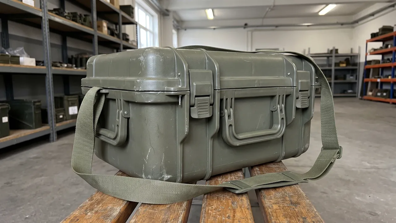
Half of what an ammunition storage box delivers comes from its shell, and the other half comes from how the interior is partitioned. Armoury keepers and storage-and-transport contractors learn this the hard way: two cases with identical wall thickness and an identical protection rating can produce very different outcomes for the goods inside once those goods have been handled repeatedly and moved over long distances. Working with armouries and logistics contractors, JUNZHIJIA treats the article described in military nomenclature as "Box, Ammunition Stowage" as a product whose internal space has to be engineered rather than merely enclosed. The shell answers rain, impact and stacking load; the layout answers interference between stored items, retrieval efficiency and counting accuracy. This article works through four layers of that logic: dividers, foam compartments, drawer trays and stacking.
In military naming convention, "Box, Ammunition Stowage" is the inverted form, and the equipment it describes sits closer to the Ammunition Storage Box idea than to a single-use shipping crate: the emphasis is on repeated circulation between storage, transfer and issue, not on one journey. That circulation creates a central tension, because the interior must keep different categories of goods apart while still leaving enough working space inside a fixed volume for retrieval and counting. Our engineering sequence is to settle the compartment logic first, then the retention method, and only then the external form of the case. Everything below stays within packaging-container engineering; local regulations and export-control requirements govern, and this article discusses packaging containers only.
Why the Interior Layout of an Ammunition Storage Box Decides Transport Safety
In a real armoury, damage is rarely caused by one violent impact. It accumulates through hundreds of small movements. When a cavity is larger than the item it holds and that item can slide freely, every lift, every loading step and every kilometre of road produces friction between the item and the cavity wall, and between item and item. Individually invisible, these displacements add up to worn coatings, chipped corners and precision features that no longer sit where they should. The first job of an interior layout is to remove that free movement at the source, so that the item is restrained by structure in every attitude.
The second job concerns retrieval. Counting and issuing in an armoury follow strict procedures, and if the case is a single loose pile, the keeper has to disturb everything else to reach one item. That lengthens the task and raises the odds of a knock. Once the case is divided by category, retrieval becomes a matched action: to take one item you open one compartment. Over months of repetition, that change contributes more reliability than any headline strength figure for the shell.
The third job is counting. A compartment layout provides a natural visual cue, because an empty slot means a missing item. For armouries that reconcile quantities on a schedule, a structure that shows absence at a glance is harder to get wrong than a list alone. We treat "can a missing item be seen immediately" as a stated design requirement rather than a feature added afterwards.
The fourth job is isolation. Different items tolerate humidity, vibration and compressive load differently, and placing them in one cavity means the sensitive item inherits the environmental stress introduced by the insensitive one. Dividing the case and giving each compartment its own liner and rust-control provision creates several small, independent environments inside one box. That principle runs through every section that follows, and it is the starting point for understanding partition logic.
The Starting Point of Partition Logic: Dividing the Case into Compartment Cells
The first step in fixing compartment cells is not drawing a grid. It is classifying what will go inside by handling behaviour. Our engineering team usually sorts items into three groups: precision parts that need individual locating, heavy parts that need load-bearing support, and general parts that can be stored in groups. These three groups need fundamentally different retention, and designing them together guarantees that at least one is compromised.
Precision parts are geometrically complex and have small clearances, so they are the most sensitive to impact and relative displacement; they suit a CNC-moulded foam cavity that holds them by contact. Heavy parts have high mass and a high centre of gravity, so what they face in transit is mostly the crushing and tipping risk created by their own inertia; they need cradles, support bars and locating channels to carry load. General parts are regular in shape and numerous, so they suit adjustable dividers forming a tidy grid, where the goal is counting efficiency rather than maximum cushioning.
Only after classification does volume allocation begin. One practical rule is not to allocate volume in proportion to item count, but in proportion to retrieval frequency multiplied by unit volume. Frequently drawn items should sit near the lid and near the outer face, while low-frequency items go to the bottom or the inner side, so that daily work disturbs the smallest possible area. In armoury use, moving high-frequency items forward typically cuts the number of handling actions per retrieval noticeably.
Once the cells are fixed, the case contains a position map. That map has to satisfy three constraints at once: like items adjacent for group retrieval; unlike items separated to avoid interference; and heavy items low to keep the centre of gravity down. When the three conflict, heavy-low wins, because centre-of-gravity height feeds directly into stability during lifting and stacking — a safety floor rather than an efficiency preference.
Divider Systems: Choosing Between Removable Bars and Fixed Partitions
Dividers are the most direct expression of partition logic, but in practice removable bars and fixed partitions are not a simple either-or. A fixed partition is moulded with the shell or permanently assembled; it is stiff, its sealing boundary is continuous, and it suits configurations that never change. Its weakness is rigidity: change the item model and the internal layout cannot follow. Removable bars, made of insert slots and divider plates, can be repositioned and replaced, which suits armouries whose contents shift with the task.
In most stowage cases we use hybrid partitioning: the interior is split into a few fixed zones, and each zone is subdivided with removable bars. The fixed zones carry structural stiffness and the load path; the removable bars carry subdivision. Each does its own job, and this division of labour is the compromise we keep returning to after real projects.
The cross-section of the bar matters as much as its position. A thin flat bar is cheap but weak against lateral bending and will bow under heavier contents, deforming the grid. A folded or ribbed section is far stiffer at the same thickness. Slot depth also has to match the weight of the contents: too shallow and the bar works its way out under vibration; too deep and adjusting plates becomes hard, which kills the flexibility that justified removable bars in the first place.
A detail that is often missed is how the bar meets the floor. If a bar simply hangs in the side slots, a gap opens between its lower edge and the case floor, and small parts migrate into the neighbouring cell. We close that gap either by seating the lower edge in a floor locating groove or by fitting a thin floor pad that the bar rests against. Either approach seals the gap and gives the bar lateral support from the floor, which reduces flexing under load.
Foam Compartments: How EVA and EPE Liners Achieve a Close Fit
When a compartment has to follow a complex outline, dividers stop being enough and foam compartments take over. EVA and EPE are the two most common liner materials, and the choice depends on whether the item needs cushioning or support. EVA is closed-cell, denser and slower to recover, with strong resistance to permanent compression set; it holds cavity shape over years, which suits parts that are located precisely and handled often. EPE is lighter and softer at a lower cost per volume, and suits cushioning layers or general-purpose liners.
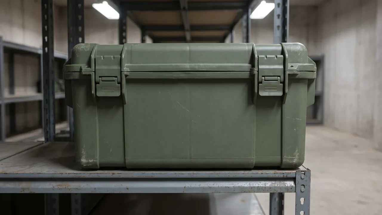
The key to CNC moulding is a close fit, not a tight fill. The cavity outline should be cut with a controlled clearance around the real item so that it is held lightly but still easy to place and remove. Too much clearance and the cavity no longer locates anything; too little and every retrieval requires force, which accelerates fraying and collapse along the foam edges. We usually fine-tune that clearance according to whether the item's edges are rounded and whether its surface scratches easily.
Layering is the other route. For tall items whose top faces need protection, the liner can be built as two layers: a lower layer that cradles and locates the base, and an upper layer in the lid that mirrors the top face, so that closing the lid sandwiches the item between them. This two-sided clamping restrains vertical bounce better than side support alone, and it suits items with a high centre of gravity that would otherwise ride up and down on rough roads.
Foam upkeep also affects how long a layout lasts. Repeated handling sheds debris from the foam edges, and debris trapped between foam and item becomes a local hard point that can mark the item's surface over time. We recommend a removable liner tray so the cavity floor can be cleaned on a schedule, and a rounded cavity lip on high-frequency cells to reduce tearing. Removable foam strips combined with a pre-cut grid are worth considering too, because they keep the close fit while leaving room for later changes.
Drawer Trays and Layered Retrieval
Not every stowage case suits a lift-the-lid layout. When the case is deep and the contents are stacked in several layers, digging downwards steadily destroys retrieval efficiency, and drawer trays earn their place. A drawer layout splits the interior vertically, with each level a tray that slides out as a whole; the tray is then subdivided with the dividers or foam described above, which turns "searching at depth" into "pulling out a tray and working near the surface".
The sliding fit between tray and case is the hard part. Too tight, and the tray jams once it has absorbed moisture or grit; too loose, and it shifts fore and aft in transit, making noise and scuffing the contents. We fit guide ribs on both sides of the tray to run in grooves on the case wall, which constrains lateral movement while keeping the pull smooth, and we add a stop at the rear so the tray cannot be pulled free and dropped.
The number of levels has to be settled together with case height and per-level load. More levels mean less clear height per level, which suits flat general parts; fewer levels mean more clear height, which suits bulky items. Tray load capacity matters too: if every tray is specified full, the lower trays carry the weight of everything above them, so the tray floor needs matching stiffness and, where necessary, additional ribs.
A further benefit of layering is that the working surface stays in view. A keeper standing at the case can comfortably reach only the front and middle of a deep tray; once the contents are layered, every level falls inside reach. The working posture is more natural, and fatigue and mis-handling over long shifts both fall. Ergonomically, that is worth more than squeezing out the last of the volume.
Cushioning and Location: Three Basic Ways to Limit Freedom of Movement
The purpose of an interior layout is to keep contents in a controlled attitude during transport and use, and the means fall into three families: clamping, locating and suspension. Clamping lets a flexible liner conform to several faces of the item so contact area spreads the impact. Locating places rigid stops or pins against a boss or hole to restrict movement. Suspension lifts the item clear of the case floor so elastic supports carry the whole load and cut the floor's impact path entirely.
Each family has a boundary. Clamping adapts well to complex shapes but depends on the liner's condition, which declines once it ages or absorbs moisture. Locating is stiff and precise but demands a thorough understanding of the item, and a stop position is hard to change once set. Suspension isolates best but places a fatigue requirement on its supports, and if a support fails the item drops directly. In practice we lead with clamping, support it with locating, and use suspension only in localised areas for unusually sensitive items.
A quick test of a layout is to imagine the case turned over, tilted and stood on end: does the item stay where it was designed to sit? If it would slide or topple in some attitude, that direction of freedom is unconstrained. In design review we have engineers simulate each attitude the case might see in service and then add stops or adjust the liner, rather than verifying only the normal resting position.
Fitting method matters too. A stop screwed directly to the wall can loosen under repeated impact as stress concentrates at the fastener, and it leaves holes that compromise sealing. Clip-in or inset locating parts are easier to replace and leave the wall intact. For users who expect substantial layout changes over the life of the case, we favour removable locating parts on pre-formed mounting positions: stability now, room to change later.
How Stacking and Palletisation Constrain the Interior Layout
Interior layout is often treated as a matter inside the case, but in real engineering, stacking and palletisation constrain it from the outside. When several cases are stacked, load must travel down through the walls and corner posts. If the layout puts all the heavy items on one side, the centre of gravity shifts away from the geometric centre, and stacking produces an eccentric load that tilts or even slides the upper case. So compartment allocation has to balance weight front to back and left to right at the same time.
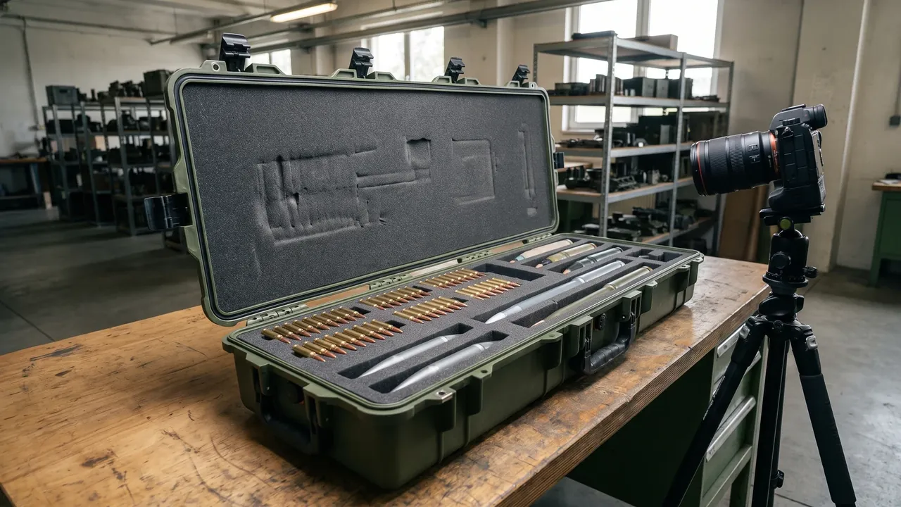
Palletisation constrains the layout through dimensions and height. A standard pallet has a fixed footprint, so case dimensions are usually set to a pallet module, and that external size then limits how the interior can be divided. With the case size and internal volume fixed, adding levels compresses clear height, and adding compartments shrinks each cell. We normally confirm the pallet and container loading plan with the customer before fixing the number of cells, so that a layout which looks good inside does not turn out not to fit a standard pallet.
Stacking also couples vertical load to internal cushioning. Compressive load on the lid travels through the lid into the liner and the contents. If the liner lacks vertical support, the lid deflects and presses on the contents. The fix is a support post running between the upper and lower walls, or a load pad between lid and liner, so stacking load bypasses the contents and reaches the case floor. A layout has to plan the load path and the storage function together.
Stacking height is part of the layout discipline as well. More layers are not automatically better: once the layer count exceeds the design capacity of case and pallet, the bottom cases creep under sustained load, the sealing faces distort, and the protection rating drops. We advise users to calculate the permitted layers per pallet from contents weight and case structure, and to mark that number clearly on the pallet so that site staff can stack correctly without doing the arithmetic.
Sealing Boundaries and Where the Pressure-Equalisation Valve Sits
Sealing is an external property, but how its boundary passes through the interior affects reliability. Once a case is split into compartments, air in each compartment can only equalise slowly through gaps between dividers, so under temperature or pressure change the compartments respond at slightly different rates, especially where loading density and liner compression differ. In high-integrity sealing designs, the layout should therefore avoid sealing any one compartment into a fully independent air pocket.
A pressure-equalisation valve handles exactly this. Mounted on the case wall, it allows slow gas exchange while a waterproof breathable membrane blocks liquid water and dust. For cases that fly or face large temperature swings, the valve is close to mandatory. Its position is usually chosen high on a wall on a serviceable side, and it must avoid areas that the liner would cover, otherwise changing the membrane means stripping the whole case. The layout should reserve a serviceable path to the valve.
Sealing-face maintenance is affected by layout too. The gasket between lid and body is the weak point of the whole case, and once grit or liner debris is trapped there, sealing fails. If the liner runs close to the sealing face, its edges or fibres are easily pressed into the gasket groove when the lid closes. We keep a clean transition band between liner and sealing face and inset the liner edge slightly, so liner material cannot interfere with the seal.
Where a low-humidity environment has to be held inside the case, sealing carries an implicit requirement: compartments must allow the desiccant to be replaced and humidity checked easily. If desiccant is buried inside the liner, the user cannot judge its condition quickly and will keep relying on a spent charge. So the layout normally places desiccant near the compartment mouth or in a dedicated cell, making scheduled replacement straightforward.
Placing Desiccant and VCI Rust Protection Inside the Compartments
In humid conditions, interior protection rests on two measures: humidity control by desiccant, and corrosion inhibition on metal surfaces by VCI material. Their placement inside a compartment is not the same. A desiccant's reach depends on air moving between it and the target compartment, so it belongs where air circulates. VCI works by releasing inhibiting molecules that form a film on metal, so its effectiveness depends on its distance from the metal surface and on how enclosed the compartment is.
The worst approach to a compartmented layout is one desiccant charge per case. If the interior is divided into near-sealed cells, a single location cannot bring every cell to the same humidity: cells near the charge run dry while distant cells stay damp. The better answer is a charge in each main compartment, or a vent gap in the dividers so compartments remain in slow air communication.
VCI placement puts more emphasis on proximity to metal surfaces. In a tightly fitted cavity, VCI film on the cavity wall or a VCI sheet is enough to keep concentration high in a small space; in larger compartments the quantity should scale with volume. Note that VCI is of limited use on surfaces that have already corroded, so items must enter the case clean and dry, otherwise the protective film cannot form evenly.
Replacement intervals for desiccant and VCI belong in routine management. We suggest a status indicator area on the outside of the case, or a visible humidity card, so a keeper can judge without opening the case. For long-sealed cases, a reusable desiccant with a defined regeneration cycle works well; for frequently opened cases, tie replacement to the return-and-count step, so it becomes a fixed part of the routine rather than something to remember.
Locks, Seals and the Mapping Between Security Zones
An interior layout serves access control as well as retrieval. Armouries usually manage their holdings in security tiers, and different tiers need different access. That requirement shows up in the layout: a high-security compartment should sit where it cannot be reached directly, or be a separately locked sub-cell, while general compartments can be grouped on one side so a single opening covers routine work.
Lock choice and layout interact. A single-point lock is simple but secures the lid at one place; if the layout lets contents be removed from any part of the lid opening, the real security of a single-point lock rests on the overall stiffness of the case. For higher security we fit a lockable sub-compartment, or use multi-point latches around the lid edge, which both tightens the lid-to-body fit and makes prying a single latch harder.
Tamper-evident seals form another layer. A seal does not stop a determined forced opening; it records that opening happened. For cases handed between units, a numbered seal fitted in addition to the lock lets the receiving side judge whether the handover was interfered with by checking the seal's condition and number. The seal should be fitted where opening must destroy it, and it should work with the lock structure so there is no path that breaks the seal while leaving the case closed.
Security zones also have to be tied to the labelling system. Where a case holds compartments of different tiers, external labelling should show each compartment's position and tier, so a keeper cannot open an unauthorised cell in a hurry. We suggest an internal layout diagram as a label inside the lid, updated whenever the layout changes, which helps daily work and also supports handover and audit.
Labelling and Traceability: Where RFID and Barcodes Land in a Divided Case
When a stowage case manages contents by compartment, identification has to reach compartment level, not stop at case level. A single barcode or RFID tag on the shell only answers where the case is; compartment-level marking answers what is in a cell, when it was placed there and by whom. For armouries and logistics contractors that need fine-grained management, that is often the main reason to choose a divided layout at all.
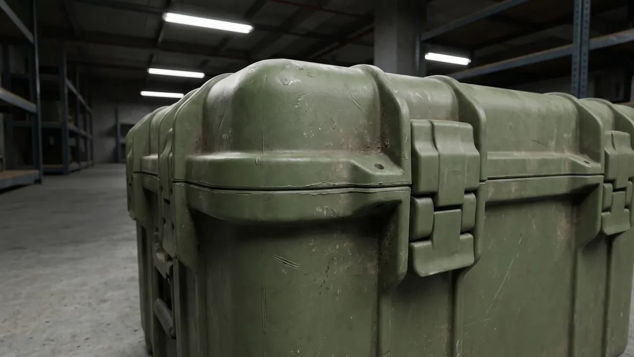
Tag position has to be planned. A barcode label sits on the compartment rim or a divider, where it is easy to scan and unlikely to be hidden by contents. An RFID tag has to account for the shielding effect of metal contents on radio signals, so it normally goes on the liner surface or a non-metallic part of a divider, spaced away from metal. We run read-write tests on a sample case and confirm the read rate in every compartment before fixing tag positions.
Tag durability is part of the layout brief as well. Tags in high-frequency cells wear or peel from friction, and tags near the compartment mouth can lose adhesion in humid airflow. We specify laminated labels and recess high-contact positions so the tag face sits flush with the liner and cannot be caught by an item edge. On removable dividers, the tag travels with the divider, so the recorded position always matches the physical one.
A traceability system has to stay in step with layout changes. Flexibility is an advantage of compartment layouts, but if a user repurposes a cell without updating labels and records, traceability drifts — the system says one thing and the case does another, which is more dangerous than having no system. So where removable dividers are used, the management routine should state that any layout change is followed by an update to the internal diagram and the traceability record, treated as a fixed step in the change process.
Materials and Structure: Matching Engineering Plastics, Steel and Fibre to the Layout
Case material limits what the interior can do. A rotationally moulded polyethylene shell is tough, moulded in one piece and corrosion resistant, but its inner wall usually has natural undulations and wall-thickness variation, so the layout must clear the high spots or use a liner to level the floor. An injection-moulded engineering-plastic case holds tight tolerances and a regular inner wall, which suits a precise grid, though tooling for large parts is costly. A metal case is stiff and takes stacking load well, which suits heavy items and long storage, but its hard inner surface means a liner is essential to keep goods off bare metal.
Fibre-reinforced cases sit between the two: light, with high specific strength, which suits frequent transfer where self-weight matters. Their walls are usually thin and carry point loads less well than metal, so a layout should avoid concentrating heavy-item load on a few contact points and should spread it with distributed supports instead. On fibre cases that will be lifted, the layout also has to reconcile lifting points with the internal centre of gravity, so a lifted case does not tip from an offset load.
Structurally, wall ribs and the interior layout interact. Ribs run at intervals along the walls and create slight inward bulges, so cells placed at those points need the liner to relief them. The relationship can be used deliberately: position the bearing points of heavy-item cells near ribs so load transfers into the reinforcement close by and local wall deflection falls. Letting the layout follow the structural load path this way visibly improves real carrying performance.
Sealing details, hinges and latches are boundary conditions for the layout. A hinge wall is usually thicker and offers less usable clear space; latch positions must match the load distribution across the lid, and if the layout makes one side clearly heavier, latch sealing pressure may be uneven. We check hardware positions against the compartment division on the same drawing during design, so a liner never blocks a latch and a heavy item never sits over a poorly sealed edge.
Testing and Acceptance: Validating the Layout Against MIL-STD-810H and GJB
Whether a layout is reliable is settled by testing. For military transport and storage environments the common references include the environmental test methods covered by MIL-STD-810H and the corresponding GJB series, alongside the GB/T 4857 series for transport packages and the ISTA procedures. These standards examine vibration, shock, drop, temperature, humidity and salt fog from different angles, and the role of the interior layout is to hold attitude and cushioning performance under exactly those conditions.
Vibration testing examines the layout most directly. It simulates sustained transport vibration and reveals whether liners and locating parts loosen, wear or resonate over long exposure. If a cell lets an item sit in a state of slight movement, vibration tends to amplify that movement until the liner collapses locally. So during layout validation we pay particular attention to cells whose clearance is not tightly controlled and which can micro-move.
Drop and shock testing examines the cushioning path. The package is struck from different angles and heights, and the check is whether the liner can absorb energy and keep the item from taking the impact directly. In layout terms the cushioning path should be continuous: from wall to liner to item there should be no hard-to-hard contact. If a boss on an item lines up with a thin spot in the liner, that point becomes a stress raiser under impact, and the layout fix is more local thickness or a revised cavity outline.
Temperature, humidity and salt-fog testing checks the moisture and corrosion arrangements. Heat and humidity accelerate liner ageing and metal corrosion, and salt fog worsens it. These tests require the desiccant and VCI placement to be effective and the sealing boundary to be sound. We inspect liner compression recovery, seal deformation and metal surface condition before and after, and use those changes to decide whether the layout needs revision. Once testing is complete, measured data and layout drawings are archived together as the baseline for later production.
The Customisation Process: Confirming the Layout from Drawing to First Article
Customising a compartmented stowage case normally starts with requirements. We collect the item list, external dimensions, weights, retrieval frequencies and storage conditions, and from these form a first compartment plan. What matters most at this stage is not drawing detail but settling the classification principle and the volume allocation, because once structural design begins the room to change shrinks quickly.
The second step is designing the layout and the case structure together. The interior has to be considered alongside external form, rib positions, hardware positions and the sealing boundary, and optimising any one in isolation will conflict with another. At this stage we issue a layout drawing showing compartment division, liner type, locating positions and label positions for customer confirmation. That approved drawing then becomes the shared basis for sampling and acceptance, which prevents later misunderstandings.
The third step is first-article sampling and physical validation. Once the sample is built, we run a full retrieval test with the real items, checking fit, ease of handling and clarity of counting. Physical validation regularly surfaces what drawings do not, such as a boss that is harder to insert than the drawing suggested or a cell that is too deep for fingers to reach. We feed these findings straight into layout revision rather than waiting until after mass production.
The last step is production and delivery management. Once the layout is frozen, the liner mould, divider specifications and label positions all become fixed, and batch consistency leans on those fixed elements. We suggest users keep a final layout drawing and first-article photographs as the reference for acceptance and later spare-part ordering; where removable dividers are used, the spare divider list should be defined too, so a single damaged bar cannot leave the whole layout unsupported.
Ammunition Storage Box FAQ
Q: Why can the same case produce very different outcomes depending on its interior layout?
A: Because the shell only addresses the external environment and overall strength, while the attitude and loading of the contents are set by the layout. When a cavity is larger than the item and the item can slide, every lift, loading step and kilometre of road creates reciprocating friction. Each displacement is tiny, but over hundreds or thousands of repetitions it becomes worn coatings, chipped corners and precision features that no longer sit correctly. A sound layout constrains that freedom to near zero through close-fitting cavities, locating stops and sensible subdivision, removing relative motion at the source. We treat "the item stays where it was designed to sit in any attitude" as the acceptance standard, rather than checking only the normal resting position. Subdivision also means a retrieval action disturbs only the current cell, which cuts the secondary knocks that come from moving other items aside. A related gain is that the layout fixes what a correct load looks like. When every item has a designated cell, a case that has been loaded carelessly looks different from one that has been loaded properly, and a supervisor can see the difference without opening a checklist. Over the life of the case, that visual standard is what keeps handling discipline from drifting.
Q: How should I choose between removable divider bars and fixed partitions?
A: The deciding factor is whether the contents will change with the task. A fixed partition is moulded with the shell or permanently assembled, so it is stiff and its load path is continuous; it suits configurations that stay constant, but it cannot follow a change of item model. Removable bars made of insert slots and divider plates can be repositioned and replaced, which suits armouries whose contents shift. We usually combine them: fixed partitions divide the case into zones that carry stiffness and load, and removable bars subdivide each zone into cells, balancing structure and flexibility. When specifying bars, note that cross-section stiffness, slot depth and how the lower edge meets the case floor all affect real performance, so state the contents weight to your supplier at selection time rather than assuming any bar will do. Also confirm how the bars are retained when the case is tipped, because a bar that relies on gravity alone can drop out of a shallow slot during handling and leave a cell open. A repeatable retention method, such as a clip or a captive end, costs very little and prevents a small part from migrating between cells after the case has been tipped or inverted in transit.
Q: Should foam compartments use EVA or EPE, and on what basis is that decided?
A: The choice follows whether the item needs cushioning or support. EVA is closed-cell, denser and slower to recover, with strong resistance to permanent compression set, so cavity shape holds over years; that suits precision parts that are located closely and handled often. EPE is lighter and softer at a lower cost per volume, which suits cushioning layers or liners for general parts where support demands are modest. Clearance design matters as much as material: too much clearance and the cavity locates nothing, too little and every retrieval needs force, which wears and collapses the foam edges. We fine-tune clearance based on whether item edges are rounded and whether surfaces scratch easily, and round the cavity lip on high-frequency cells. For tall items whose tops need protection, we build the liner in two layers so the upper and lower cavities clamp the item together and restrain vertical bounce. Remember that foam and the items it holds both age. A liner that held a part firmly on the first day will feel looser after a year of use, so the layout should be reviewed whenever a case is reissued or its contents change. Replacing a worn insert is far cheaper than replacing the item it was meant to protect, which is why we treat liner condition as part of routine maintenance rather than a one-off choice.
Q: How should desiccant be placed in a compartmented case to work properly?
A: It should be placed per compartment rather than as one charge for the whole case. A desiccant's reach depends on air moving between it and the target compartment; if the interior is divided into near-sealed cells, one location cannot bring every cell to the same humidity, and cells near the charge run dry while distant ones stay damp. The better approach is a charge in each main compartment, or a vent gap in the dividers so compartments stay in slow air communication. We also suggest putting desiccant at the compartment mouth or in a dedicated cell for easy replacement. For long-sealed cases, a reusable desiccant with a defined regeneration cycle works well; for frequently opened cases, tie replacement to the return-and-count step so it becomes routine, and a spent charge is never left in place by mistake. Where the budget allows, a small visible humidity indicator removes the guesswork entirely. A keeper who can see that the indicator has changed colour will replace the charge on the spot, while a case that gives no feedback tends to keep a spent charge for months without anyone noticing. Simplicity of checking is what makes the whole arrangement reliable in daily use.
Q: Where should RFID and barcode tags go in a divided stowage case?
A: Balance readability, durability and metal shielding. A barcode label suits the compartment rim or a divider, where scanning is easy and contents rarely hide it. An RFID tag must account for the shielding effect of metal contents, so it usually goes on the liner surface or a non-metallic part of a divider, spaced away from metal. Before freezing positions we run read-write tests on a sample case and confirm the read rate in every compartment, so we do not discover after production that some cells cannot be read. On durability, tags in high-frequency cells wear and tags near the compartment mouth can lose adhesion in humid airflow, so we specify laminated labels and recess high-contact positions so the tag sits flush with the liner. On removable dividers the tag travels with the bar, keeping recorded position aligned with physical position. One more point is scope. Decide early whether traceability is needed at case level, compartment level or both, because a system designed for one level cannot simply be extended later without re-tagging. Where compartment-level records are required, plan the tag positions and the database fields together, so that the physical layout and the digital record are designed as one system rather than two.
Q: Does the interior layout affect how well the case stacks? A: Yes, and the effect is often underestimated. Stacking load must travel down through the walls and corner posts; if the layout puts all heavy items on one side, the centre of gravity shifts from the geometric centre and the stack carries an eccentric load that tilts or slides the upper case. Stacking load also reaches the liner and contents through the lid, so if the liner lacks vertical support the lid deflects and presses on the goods. We therefore plan the load path alongside the layout: a support post running between the upper and lower walls, or a load pad between lid and liner, so stacking load bypasses the contents and transfers to the case floor. The layout should also be confirmed together with the pallet plan, fixing case size against the pallet module before setting the number of cells.
A tall, dense column of small cases also behaves differently from a low, wide footprint, so the layout decision belongs to the storage plan, not only to the item list. Check the corner posts and lid lands for crush damage during audits, because those are the points where a poor interior layout first shows up as a structural complaint.
Q: What is the relationship between a pressure-equalisation valve and the sealing boundary of a divided case? A: It concerns how the sealing boundary runs. Once a case is split into compartments, air equalises only slowly through gaps between dividers, and under temperature or pressure change the compartments respond at slightly different rates, especially where loading density and liner compression differ. If one compartment becomes a fully independent air pocket, pressure change can destabilise the seal. A pressure-equalisation valve on the wall allows slow gas exchange while blocking liquid water and dust, and it is close to mandatory for cases that fly or face large temperature swings. Position it on a serviceable side and clear of areas the liner would cover, otherwise changing the membrane means stripping the case. We reserve a serviceable path to the valve in the layout and include the valve in the maintenance checklist, so a dust-clogged membrane is caught before it fails.
Treat the valve as part of the sealing boundary that happens to move. Specify a membrane rated for the same pressure band as the gasket, mount it where cleaning is possible without tools, and include a simple function check in the periodic inspection so a blocked valve is caught before it turns a sealed case into a drum.
Q: What steps does a custom compartmented stowage case go through from requirement to delivery?
A: Four steps in practice. First, requirements: collect the item list, external dimensions, weights, retrieval frequency and storage conditions, and form a compartment plan; the priority is to settle the classification principle and volume allocation, because room to change shrinks once structural design starts. Second, design the layout and case structure together, considering liner type, locating positions, ribs, hardware and the sealing boundary, and issue a layout drawing for confirmation. Third, first-article sampling and physical validation, running a full retrieval test with the real items and feeding findings directly into layout revision. Fourth, production and delivery management, where the frozen layout fixes the liner mould, divider specifications and label positions so batch consistency is maintained. Keep the final drawing and first-article photographs, as they are the reference for acceptance and spare-part ordering.
Related Reading
- Customizing Ammunition Box Foam Inserts: Engineering the Close Fit
- Comparing Internal Foam Types: EVA, EPE and Polyurethane
- Removable Divider Systems for Protective Cases
- Dividers or Foam: Choosing the Right Interior Solution
- Pre-Cut Foam in Protective Cases: The Trade-offs of a Standard Grid
- Tactical Gear Box Interior Layout: Organising Equipment Zones
- Modular Case Systems: Design Logic for Combinable Compartments
- Stacking and Storing Military Ammunition Boxes: Palletisation Points