

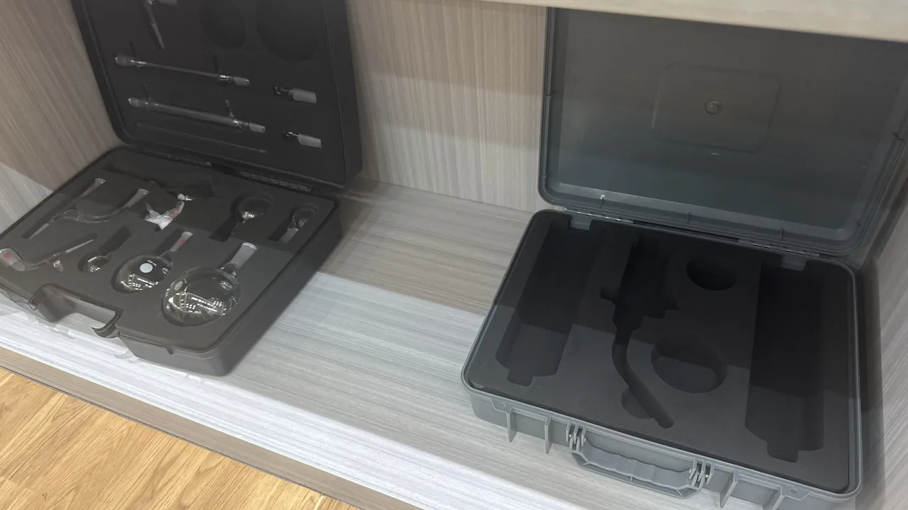
A line-replaceable unit, or LRU, travels a long way between removal from an aircraft and reinstallation: the apron, the hangar, a bonded store, a road vehicle and sometimes the hold of a freighter. During that path none of the operations is supervised by the aircraft's own systems. The electronics enjoy shielding, grounding and temperature control only while powered and installed; the moment they are de-energised and off the airframe, all of that disappears, leaving only the case, the liner and the operator's hands.
JUNZHIJIA takes a firm position on this category: packaging for airborne electronic units must be designed for the worst site the unit will see after removal, not for the comfortable conditions of the hangar. Protection for static-sensitive assemblies, precision connectors and vibration-sensitive racks must hold simultaneously across handling, transport and storage, and every step must be recorded and traceable. Treating the case as a passive box is the single most common reason expensive avionics arrive damaged in ways that only surface as intermittent faults after power-up.
Table of Contents
- 1. Field Risks for Airborne Electronic Units
- 2. Handling Path Through Line Maintenance and MRO
- 3. ESD-Sensitive Component Protection: Bonding, Conductive Liners, Humidity
- 4. Connector Protection: Dust Caps, Pins and Insertion Limits
- 5. Shock and Vibration Limits for Racks and Modules
- 6. Recording and Documentation of Handling
- 7. Traceability: Labor Tags, Part Numbers and Serial Numbers
- 8. Transport Between Bases, Hubs and Shops Including Air
- 9. Site-Type Environment Limits Comparison
- 10. Handling Checklist
- 11. Shell Structure, Sealing and Pressure Equalisation
- 12. Liner and Compartment Design
- Frequently Asked Questions FAQ
- Conclusion and Related Reading
1. Field Risks for Airborne Electronic Units
Airborne electronic units share a set of traits that set their storage and transport risk apart from ordinary industrial electronics: high unit cost, precision interfaces, sensitivity to electrostatic discharge and vibration, and a daily handling model built around removal and replacement rather than repair. That combination means a unit is almost always picked up and set down on its own, rather than shipped inside a larger assembly, and it is almost always moved through several sites of very different character.
| Risk category | Typical manifestation | Effect on the unit | Packaging countermeasure |
|---|---|---|---|
| --- | --- | --- | --- |
| Electrostatic discharge | Dry climate, synthetic gloves, friction in plastic totes | Input-stage device breakdown, latch-up | Conductive liner, equipotential point, humidity indicator |
| Moisture and condensation | Hangar air conditioning versus apron temperature swings | Connector pin oxidation, board leakage | Desiccant, humidity card, equalisation valve |
| Vibration and shock | Road roughness, handling knocks, hold loading | Fastener loosening, crystal and relay damage | Cushioning liner, compartment location, shock indicator |
| Connector damage | Repeated mating, off-angle insertion, debris | Bent pins, worn key, rising contact resistance | Dust caps, blind-insertion guides, insertion log |
| Mixed or wrong units | Same type, different configuration stored together | Wrong fit, hidden functional loss | Compartment label, part and serial tag |
| Broken traceability | Labor tag lost, paperwork separated from unit | Missing maintenance record, unclear responsibility | Case binding, document pocket, QR association |
What unites these risks is that none of them reveals itself the instant the case is opened. They appear later, as intermittent faults after the unit is reinstalled and powered. The value of storage and transport protection, therefore, is not "preventing breakage" but holding damage within a detectable level and leaving a traceable record behind.
2. Handling Path Through Line Maintenance and MRO
The same LRU experiences completely different conditions during line maintenance on the apron and during a visit to an MRO workshop. Line maintenance happens on the open apron, under time pressure, exposed to wind-blown grit and wide temperature variation; an MRO shop has a controllable pace, a stable environment, but high batch throughput and strict work-order binding.
| Path node | Environment | Main risk | Packaging requirement |
|---|---|---|---|
| --- | --- | --- | --- |
| Apron line swap | Open, gritty, temperature-variable, time-limited | ESD, debris, knocks | Portable tote, one-hand access, single-hand retrieval |
| Hangar staging | Temperature-controlled, medium cleanliness | Mixed units, lost tags | Compartment location, visible part and serial |
| Bonded store | Constant temperature, account managed | Broken traceability, over-stay | Case-number binding, validity and QR |
| Road transfer | Vibration, stacking, handling | Shock, liner shift | Cushioning liner, stacking-limit mark |
| Freighter air leg | Low pressure, low temperature, multiple transfers | Seal negative-pressure deformation, condensation | Equalisation valve, humidity indication |
| Workshop bay | Stable, testable | ESD, unpacking damage | ESD workstation, conductive liner |
In the apron swap scenario, the real constraint on packaging design is the working posture: one person, one free hand, strong wind, poor light, uneven ground. If the lid needs two hands to open, the latch needs precise alignment, and the liner needs to be pried out, the operator will simply carry the case half-open. Protection that conflicts with the real posture on the ground is useless no matter how high its rating. A line tote should meet three requirements: one-hand lid opening, part number visible the instant the lid opens, and the unit released from location with no extra tool.
3. ESD-Sensitive Component Protection: Bonding, Conductive Liners, Humidity
Avionics assemblies are almost always static-sensitive, and the protection logic should follow the electrostatic-control practice described in the IEC 61340 family: manage the three paths of charge generation, accumulation and dissipation together.
The first element is equipotential bonding. The operator, the bench, the case and the unit should sit at the same potential, so that no potential difference drives a discharge. The most direct practice is to have the operator touch a metal bonding point on the case with a wrist strap or a conductive glove before opening the lid.
The second element is a conductive or static-dissipative liner. The liner surface resistance must sit in the dissipative band, not the insulating band. A fully insulating foam lets charge sit on the surface for a long time and concentrates it into a discharge the moment the part is touched. A conductive liner, combined with a compartment layout, drains charge along the liner to the case ground.
The third element is humidity control. When relative humidity is too low, for example below 30 percent, almost every material accumulates static charge more readily; too high promotes corrosion. Practice usually holds storage between 40 and 60 percent relative humidity and records the limit with a humidity indicator card.
| Control element | Target state | Common error | Check method |
|---|---|---|---|
| --- | --- | --- | --- |
| Equipotential bond | Operator and case at same potential | Bare-hand contact with board | Wrist-strap test, visual bond point |
| Liner material | Static-dissipative band | Insulating foam used | Surface-resistance record |
| Relative humidity | 40 to 60 percent RH | Long periods below 30 percent | Humidity card reading |
| Ground continuity | Case to ground bar conductive | Loose ground wire | Continuity sampling |
| ESD gloves | Equivalent to wrist strap | Synthetic glove substitute | Glove specification check |
| Transport friction | No relative liner slip | Excess compartment clearance | Post-transport liner check |
A reminder worth repeating: static damage is often delayed. A single discharge may only weaken a device without immediately breaking it, showing up as an intermittent anomaly months later. ESD protection is therefore a procedure repeated at every pick-up and set-down, not a one-time action.
4. Connector Protection: Dust Caps, Pins and Insertion Limits
The connector is the most exposed part of an airborne electronic unit and the part with the highest count of life-cycle actions and the highest chance of injury. Its failure modes fall into three classes.
Bent or deformed pins come from off-angle insertion or side load during mating. The prevention is a blind-insertion guide: a slot on the connector side of the case that holds the unit at the correct attitude during removal and replacement.
Foreign-object contamination is the second class. Aviation sites carry dust, sealant debris and fibre. Once debris enters a socket it raises contact resistance or, with moisture present, forms a corrosion nucleus. A dust cap is the cheapest countermeasure, but the cap must travel with the unit, the case and the position; the moment it is removed and dropped into a pocket, the loss rate climbs sharply. The case should hold a dedicated pocket for the removed cap.
Insertion-count accumulation is the third class. Most connectors carry an explicit mating life, after which contact resistance and insertion-force scatter rise markedly. Recording mating count on the labor tag is one of the lowest-cost management tools available.
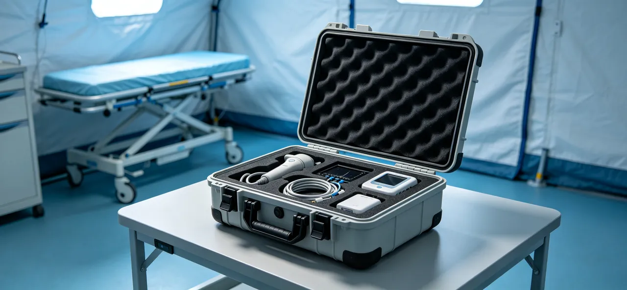
| Connector failure mode | Trigger | Consequence | Packaging and procedure countermeasure |
|---|---|---|---|
| --- | --- | --- | --- |
| Bent pin | Off-angle insertion, side load | Poor contact, short risk | Guide slot, attitude limit |
| Worn key | Forced mating | Lost error-proofing, wrong mate | Insertion-force limit, no forced mate |
| Debris ingress | Dust, debris, fibre | Rising resistance, corrosion | Dust cap, dedicated pocket |
| Seal ageing | Long exposure, temperature cycles | Lower protection | Environmental seal, periodic change |
| Over-mating | Repeated assembly | Contact scatter, bit errors | Log record, life warning |
| Lost label | Tag detached | Wrong mate, broken trace | Laser etch, dual label |
For frequently swapped units, printing a connector insertion-count sheet inside the lid, ticked by the operator after each cycle, costs a few seconds yet warns of end-of-life before a contact problem is misdiagnosed as a board fault.
5. Shock and Vibration Limits for Racks and Modules
Rack-mounted avionics sit in a controlled vibration environment on the aircraft, while in storage and transport the vibration and shock spectrum is set by vehicles, handling and manual moves, which do not match. The goal of transport protection is therefore not to reproduce the on-board environment but to hold the peak acceleration of transport within the range the liner can absorb.
| Unit type | Typical mass | Main sensitivity | Cushioning strategy |
|---|---|---|---|
| --- | --- | --- | --- |
| Board assemblies | 0.3 to 1.5 kg | Board edge, connector root | Board-edge support, avoid cantilever |
| Small and medium LRU | 2 to 12 kg | Mounting ears, shell corners | Corner wrap, bottom load layer |
| Larger rack unit | 12 to 35 kg | Panel, handle, rail | Bottom load beam, handle clearance |
| Rotating parts | Variable | Bearing, rotor | Axial limit, radial support |
| Optical and display | Variable | Glass panel, backlight | Panel relief, pressure-free liner |
Experience shows that manual-handling shock is often more severe than vehicle vibration: a single drop from, say, 0.8 metres produces a peak acceleration far higher than hours of road transport. Drop tests are therefore banded by mass, while vibration tests are applied as a spectrum. To judge after the fact whether a rough-handling limit was exceeded, an irreversible shock or tilt indicator on the case provides objective evidence of whether the unit was handled roughly.
The transport test exists to verify the packaging's resistance to shock and vibration, and its pass or fail criterion should come from the purchase specification and the agreed test plan. It should not be read as any statement about the unit's own airworthiness, installation qualification or any form of approval. The MIL-STD-810H case compliance discussion sets out how such test plans are framed without implying any certification of the unit itself.
6. Recording and Documentation of Handling
The special problem with avionics units is that the same unit changes hands between several organisations: base, hub, shop and carrier each hold part of the record, and any gap creates a responsibility vacuum. The case should therefore carry a light but complete record carrier.
| Record carrier | Content | Location | Purpose |
|---|---|---|---|
| --- | --- | --- | --- |
| Shock and tilt indicator | Whether a limit event occurred | Outside of case | Post-event handling judgement |
| Humidity indicator card | Whether internal humidity exceeded limit | Visible inside lid | Moisture judgement |
| Temperature and humidity logger | Full temperature and humidity curve | Liner recess | Objective data in dispute |
| Opening record | Open time, appearance, accessory completeness | Document pocket | Handover confirmation |
| Handling note | Both parties and time | Document pocket | Responsibility split |
| Repair and test record | Fault description and conclusion | Travelling with unit | Trace closure |
The value of a record is traceability, not volume. The practical move is to compress that information onto a single travelling tag: case number, part number, serial number, last calibration or test date, shock-indicator status. The rest of the documents go into the document pocket or an electronic ledger. The approach mirrors the thinking behind asset QR-code tracking, where one scan reads every key field, and it is why JUNZHIJIA treats the case as a data object as much as a physical one.
7. Traceability: Labor Tags, Part Numbers and Serial Numbers
Part number and serial number are the identity of an avionics unit. The most common traceability failure in storage and transport is not "no record" but "record not matching the physical unit": the case holds the same part number but a different serial, or the labor tag falls off during handling.
Identification should be redundant in three layers: an etched or nameplated mark on the unit itself, a matching mark at the compartment, and a label outside the case. As long as any one layer is readable, the trace chain holds.
| Identification layer | Content | Durability requirement | Note |
|---|---|---|---|
| --- | --- | --- | --- |
| Unit body | Part number, serial, configuration | Same life as unit | Use manufacturer marking |
| Compartment mark | Serial matching the body | Abrasion and wipe resistant | Print or laminated label |
| Outside label | Case, part, serial, quantity | Weather and handling resistant | May carry QR |
| Labor tag | Removal date, operator, mating count | Removable, no residue | Replaced each cycle |
| Document pocket list | Packing list and certificates | Moisture-proof or laminated | Checked item by item |
The position of the labor tag matters: it should sit at the first sightline after opening, not at the case bottom or under the liner. If the tag sits where the unit must be removed to see it, the on-site check is routinely skipped and the trace step becomes formal only. JUNZHIJIA therefore prints the tag position into the liner layout rather than leaving it to chance.
8. Transport Between Bases, Hubs and Shops Including Air
The typical avionics logistics structure is a three-tier base-hub-shop model. The base owns line maintenance and inventory, the hub owns transit and consolidation, and the shop owns deep repair and test. The packaging requirement changes with each leg.
| Transport mode | Environment | Main risk | Packaging point |
|---|---|---|---|
| --- | --- | --- | --- |
| Short road leg | Vibration, frequent handling | Shock, stacking crush | Cushioning liner, stacking limit |
| Long road leg | Sustained vibration, temperature change | Liner shift, condensation | Reliable location, valve, desiccant |
| Freighter air leg | Low pressure, low temperature, many transfers | Seal negative pressure, condensation, loss | Valve, reliable seal, clear marking |
| Hand-carry or dedicated | Manual handling, strong temperature swing | Drop, ESD | Portable case, ESD liner |
| Small-parcel express | Sorting shock | Extreme shock, mixed load | Shock-resistant liner, separate pack |
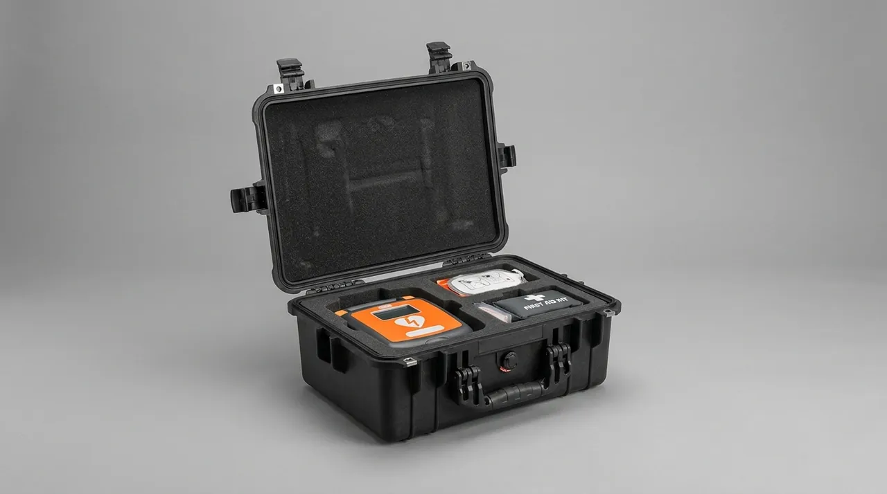
The most overlooked factor on the air leg is low pressure. The cruise-altitude hold sits well below ground pressure; a well-sealed case without an equalisation valve builds positive differential that keeps pressing the seal, then on landing turns to negative pressure that sucks humid outside air in on opening. A hydrophobic breathable equalisation valve avoids this. The discussion of pressure equalisation valve selection applies here directly. Air waybills and travelling documents should be stored separately so the case is not opened repeatedly for document checks, and the transport vibration testing basis should be stated in the procurement specification rather than assumed.
9. Site-Type Environment Limits Comparison
The table below summarises the packaging and storage requirements of different sites so they can be quoted directly in a purchase specification. The figures are common ranges from engineering practice; the actual project should follow the unit's own environmental specification and the procurement agreement.
| Site type | Temperature range | Relative humidity | Cleanliness and dust | ESD control | Recommended protection |
|---|---|---|---|---|---|
| --- | --- | --- | --- | --- | --- |
| Apron line work | With climate, minus 10 to plus 45 C | With climate | Sand and dust evident | Required | Portable tote, dust seal |
| Hangar | 15 to 30 C | 40 to 60 percent | Medium | Required | Compartment case, ESD liner |
| Bonded store | 15 to 28 C | 45 to 60 percent | Low | Required | Sealed case, account binding |
| Workshop bay | 20 to 26 C | 40 to 60 percent | Low | Required | Sealed case plus ESD bench |
| Road vehicle | minus 10 to plus 50 C | Highly variable | Medium to high | Liner dependent | Cushion plus valve |
| Freighter hold | Often 0 to 30 C, can be lower | Low to medium | Low | Liner dependent | Valve plus anti-condensation |
| Open temporary store | Extreme swings | Rain and snow | High | Liner dependent | High-grade seal plus rain cover |
Two boundary conditions matter when using the table. First, the temperature range describes the environment, not the inside of the case; the case temperature lags because of the thermal inertia of the cushioning, which is decisive for condensation judgement. Second, the "required" in the ESD column refers to the working condition: regardless of packaging rating, personnel on the apron and in the hangar must follow ESD procedure.
10. Handling Checklist
Compress the conclusions of the preceding sections into an executable checklist that can be printed inside the lid or on a travelling card.
| Stage | Check item | Criterion |
|---|---|---|
| --- | --- | --- |
| Before pickup | Case appearance and seal | No damage, no lifted edge, no debris |
| Before pickup | Shock and tilt indicator | Not triggered, not changed colour |
| Before pickup | Humidity indicator card | Within allowed band |
| Before pickup | Outside mark matches work order | Part, serial, quantity match |
| On opening | Equipotential action | ESD step executed |
| On opening | Dust caps and accessories | Complete, correct position |
| During handling | Case attitude | "This way up" as marked |
| During handling | Stacking tiers | Within marked limit |
| On refit | Compartment location | Unit fully seated, no cantilever |
| On refit | Labor tag update | Mating count ticked |
| On handover | Opening record | Both parties confirm and sign |
| On arrival | Appearance and accessory check | Matches packing list item by item |
The difficulty with the checklist is not content but timing: apron work happens under time pressure. Keep the list under ten items and place the actions completable outside the case — appearance, indicator, humidity card, mark check — at the front, so the operator completes most confirmation before lifting the case.
11. Shell Structure, Sealing and Pressure Equalisation
The shell of an avionics case is built around three points: light, strong and reliably sealed. Injection-moulded shells suit the batch rotation of small and medium LRUs; rotomoulded shells suit higher mass and impact requirements.
Sealing structure. The gasket should be embedded as a continuous joint-free ring in a groove, compressed by lid closure to form the seal. Compression is usually held at 20 to 30 percent; too little leaks, too much accelerates ageing. The seal material can follow the gasket and O-ring material selection guidance, trading temperature range against media resistance.
Pressure equalisation valve. This is essential on the air leg. A hydrophobic breathable membrane allows slow pressure balance, avoiding the case being pressed against its seal at low pressure and sucking moisture in on landing. The valve body should be mounted clear of any floor pooling zone.
Structure and reinforcement. Corner and stacking-bearing faces need reinforcement ribs; handle and latch load paths should connect directly to the shell frame rather than only to thin walls. For larger cases needing forklift or crane handling, fork slots or lifting points should be reserved in the base.
| Structure element | Key parameter | Common failure | Design point |
|---|---|---|---|
| --- | --- | --- | --- |
| Shell wall thickness | 3 to 6 mm with ribs | Corner cracking | Corner reinforce, radius transition |
| Gasket | 20 to 30 percent compression | Age hardening, permanent set | Joint-free ring, silicone or EPDM |
| Equalisation valve | Opening differential and flow | Membrane clog | Clear of pooling, periodic check |
| Latch | Open force and cycle life | Jam, break | Match seal compression |
| Hinge | Opening angle and play | Sag, loose lid | Metal pin with stop |
| Handle | Static and dynamic load | Root crack | Load to frame |
Sealing performance should be verified under load. When the case is stacked and bearing weight, the side walls flex slightly, and if the gasket contact face sits mid-wall, the flex changes the actual compression. The test should therefore include a loaded sealing check.
12. Liner and Compartment Design
Airborne electronic units vary enormously in shape: boards are thin plates, LRUs are boxes, rack units carry panels and handles. The liner must simultaneously locate, cushion, resist moisture and dissipate static.
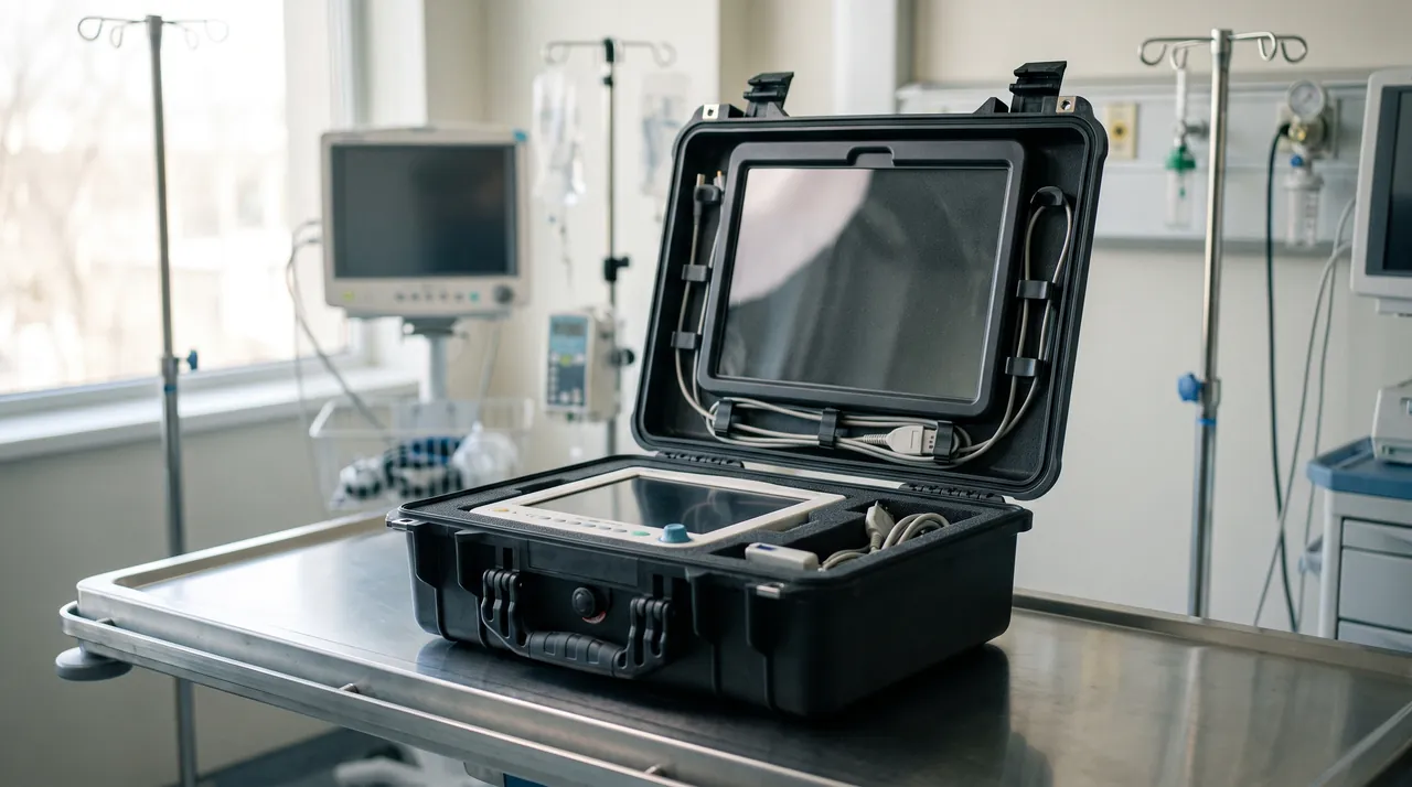
The common combination is an EVA locating skeleton, an EPE shock-absorbing layer and an IXPE moisture barrier, with a conductive layer laminated on the contact face. EVA is numerically cut to grip the unit outline and stop relative sliding in transit; EPE fills the inter-compartment gaps and absorbs shock energy; IXPE, with high closed-cell ratio, reduces vapour penetration; the conductive layer drains static to the case ground.
| Material or structure | Function | Suits | Caution |
|---|---|---|---|
| --- | --- | --- | --- |
| EVA skeleton | Precise location | LRU, board box | Avoid interference that hampers pick-up |
| EPE cushion layer | Absorb shock | All assemblies | Thickness matches limit |
| IXPE moisture layer | Reduce vapour | Humid routes | Does not replace desiccant |
| Conductive laminate | Drain static | Static-sensitive parts | Must connect to ground |
| Dedicated pocket | Hold caps and accessories | Connector accessories | Fixed position, easy reach |
| Document pocket | Hold certificates and records | Travelling documents | Separate moisture barrier |
Compartment design should also consider finger access. If adjacent cells sit flush together, a gloved finger cannot insert, and the operator will instead pull the unit by its edge, which over time damages the board edge or mounting ear. A 10 to 15 mm finger-notch per cell, placed away from the connector side, is the usual remedy. The aerospace equipment case practice of treating the liner as a removed-as-one-piece assembly is the model JUNZHIJIA applies here.
Frequently Asked Questions FAQ
Q: Why can avionics not simply use a general industrial electronics packaging scheme?
A: Because its handling path and disposition are more complex. Industrial electronics often ship as a whole and arrive once, whereas an airborne unit is handed between apron, hangar, bonded store and shop, and every handover includes opening, pick-up and repacking. That means high exposure frequency, large site differences and each site owning only a short segment of responsibility. If a general industrial pack is reused, the common problems are not obvious breakage but three hidden damages: static accumulation, connector debris and broken traceability. An avionics scheme must therefore meet location precision, static dissipation, connector protection and a record carrier together, not merely thicken the wall. The cost of getting this wrong is not a cracked shell but an intermittent fault that appears only after the unit is reinstalled and powered, by which point the storage and transport phase is no longer under observation. The economic argument points the same way: a single airborne unit can cost more than a thousand plain boxes, so the packaging budget is best spent on the four functions that actually fail in the field rather than on a thicker wall that still leaves static, debris and traceability unsolved.
Q: When line-maintenance conditions are constrained, what should packaging prioritise?
A: It should prioritise the real constraints of working posture. Apron work is typically one person, one free hand, wind and poor light; if the lid needs two hands, the latch needs precise alignment and the liner needs forceful extraction, the operator will carry the case half-open and protection fails. A line tote should meet three conditions: one-hand lid opening; part and serial visible at first sightline after opening; and unit removal without extra tools. These three seem unrelated to protection rating yet decide whether protection is actually executed. Removing inconvenience lowers field failure rates more than thickening the wall. The practical test is simple: if a procedure cannot be completed outdoors, in wind, by one gloved hand, it will be skipped, and the rating printed on the nameplate will not protect the unit in the field. Field audits of line operations repeatedly show the same pattern: the best-designed case is the one whose protection survives being opened in a hurry, in the rain, by a tired technician. Design that ignores the hurry, the rain and the tiredness is design for a laboratory, not for an apron.
Q: Why does static protection stress equipotential bonding rather than just conductive material?
A: Because the root of static damage is the discharge driven by a potential difference, not merely the presence of charge. If the operator, bench and unit sit at different potentials, even a conductive liner can still form a discharge path at the moment of contact. Equipotential practice puts operator, bench, case and unit at the same potential so there is no driving force. A conductive or dissipative liner then provides the drain path so charge does not linger on insulating foam; the two are complementary, not alternatives. Humidity control also matters, because below about 30 percent relative humidity almost every material accumulates charge more easily, and holding storage near 40 to 60 percent is the usual safe band. None of these three elements works alone, which is why a single antistatic bag is never an adequate substitute for a bonded procedure. Documenting the bond step also matters: a signed ESD check on the opening record proves the procedure was followed, which protects both the maintainer and the operator when a unit later shows a static-related fault and the question becomes whether handling was at fault.
Q: Why record the connector mating count specifically?
A: Because most connectors have an explicit mating life, and once exceeded the scatter of contact resistance and insertion force rises markedly, with faults appearing as intermittent bit errors or signal drift that are easily misdiagnosed as board or software problems, triggering whole-unit replacement. Recording the count on the labor tag costs almost nothing yet warns of end-of-life inside a planned window instead of during operation. The record also serves traceability: as the unit moves between sites, the mating count is the only objective indicator of its actual usage intensity. For high-value or safety-related units this count can be linked to a removal schedule, so the connector is replaced on a planned basis rather than after a fault, and the cost of one connector is traded against the far larger cost of an unplanned aircraft-on-ground event. When the same part number circulates through several workshops, the count tells the maintainer whether a connector is near its limit long before a contact fault forces an unplanned removal on the line.
Q: Why does the freighter air leg need a pressure equalisation valve?
A: Because the cruise-altitude hold sits well below ground pressure, and a well-sealed case builds positive differential during climb that keeps pressing the seal, then turns to negative on landing and sucks humid outside air in on opening. That push and pull both ages the seal and carries moisture inside. A pressure equalisation valve uses a hydrophobic breathable membrane for slow pressure exchange, blocking liquid water while preventing differential build-up. Selection should consider opening differential, flow and membrane area; too small an area cannot balance during fast pressure change. The mount should clear floor pooling and be checked periodically for dust or grease. Without the valve, the case that protects perfectly on the ground can still admit moisture at the very moment it is opened after a flight. Carriers and forwarders rarely know the case contains sensitive electronics, so the valve and its membrane rating should be specified by the buyer, not left to a generic "sealed case" description that says nothing about pressure behaviour across the flight profile.
Q: Why make part and serial identification redundant in three layers?
A: Because the most common traceability failure in storage and transport is a record that does not match the physical unit, not the absence of any record. The three layers cover different scenarios: the body mark serves long-term identity, the compartment mark serves quick check at opening when the body is hidden, and the outside label serves inventory and handover without opening. They differ in role and cannot replace each other. The labor tag should also sit at the first sightline after opening; if it needs the unit removed to be seen, the check is routinely skipped and trace becomes formal only. Redundancy is not wasted effort here, because a single lost label on a high-value unit can stop a maintenance action or, worse, cause a wrong-fit that only shows up in service. In practice the three layers also speed up every handover: the outside label lets stores scan without opening, the compartment mark lets the bay confirm identity in seconds, and the body mark remains as the final court of appeal if the other two are damaged or lost.
Q: What are the key criteria for avionics case sealing and structure?
A: Three points. First, gasket compression, usually 20 to 30 percent; too little leaks, too much accelerates ageing, and the gasket should be a joint-free continuous ring in its groove. Second, sealed performance under load: stacked cases flex their side walls, and if the gasket contact face sits mid-wall the flex changes actual compression, so a loaded sealing check is mandatory. Third, load path: handle and latch loads should transfer to the shell frame, not only to thin walls, or roots crack after repeated handling. Larger cases needing forklift or crane should reserve fork slots or lifting points in the base. JUNZHIJIA specifies all three as acceptance clauses rather than marketing claims, because the first two decide whether the cavity stays clean and the third decides whether the case survives its own handling. Each of the three points is independently verifiable at goods-in: compression can be measured, the loaded seal can be pressure-tested, and the load path can be checked against the drawing, so the specification turns a marketing claim into three accept-or-reject measurements.
Q: Beyond cushioning, what else must liner design consider?
A: At least four more functions: location, moisture resistance, static protection and accessory storage. Location decides whether the unit slides in transit and is usually done by a numerically cut EVA skeleton, but interference fit that hampers pick-up must be avoided. Moisture resistance combines high closed-cell material with desiccant, and material alone does not replace desiccant. Static protection requires a dissipative contact face connected to case ground. Accessory storage targets the most lost items, dust caps and terminal guards, with a fixed dedicated pocket. Between cells, a 10 to 15 mm finger-notch placed away from the connector prevents edge-pull damage. A liner that does only one of these four will either let the unit move, let moisture in, let charge build, or let the cap disappear.
Conclusion and Related Reading
Storage and transport protection for airborne electronic units is really about covering the un-supervised interval after removal: a locating liner replaces the mounting rack, static dissipation replaces on-board grounding, and a record carrier replaces the maintenance ledger. Design for the worst site and fold every opening into procedure.
Related Reading