


The purpose of a railway signal equipment case is not to prevent breakage, it is to prevent performance drift. These are completely different objectives. A signalling system is built from a large number of components that operate at low voltage and very low current: relay contacts carry milliamps, track circuit receivers discriminate millivolt differences, and point machine indication circuits depend on the consistent position of contacts. The common characteristic is that the signal-to-noise margin is inherently small, so any change in contact resistance, any shift in a magnetic air gap, and any invisible oxide film can leave equipment that looks fine, measures marginally out of tolerance, and behaves erratically once installed. Arrival inspections of signalling equipment pass on appearance almost every time, yet contact pressure changes, partial demagnetisation, insulation resistance falling to a marginal value and core air-gap variation are exactly the faults that are hardest to trace during commissioning.
The second difficulty comes from the environment. Trackside equipment lives in lineside cabinets, location cases and equipment rooms, exposed for years to vibration, humid heat, dust and temperature cycling. The rail industry describes this severity through GB/T 21563, on shock and vibration testing of rolling stock equipment, and IEC 61373, which define shock and vibration levels for equipment mounted on car bodies, bogies and axles, while EN 50155 specifies the operating conditions and test requirements for electronic equipment used on rolling stock. Those standards address in-service conditions, but the transport chain simply applies the same severity one step earlier: road roughness, shunting impacts, and the long-period roll plus salt spray of a sea voyage all complete a first screening round before the equipment ever reaches the depot.
This article is written for signalling equipment manufacturers, railway signalling and telecommunications department staff, metro construction and maintenance organisations, signal equipment traders and exporters, and the procurement and logistics teams of system integrators and third-party test houses. It covers transport protection for safety relays, track circuit equipment and impedance bonds, point machines and switch control components, trackside electronic units, power supply panels and surge protective devices, and cable, terminal and connector accessories, including failure modes, moisture-control design, retention and zoning, standards references, a selection comparison table, a packing SOP and goods-in verification methods. All figures are typical industry values or empirical ranges; the equipment technical specification, drawings and destination regulations take precedence. JUNZHJIA provides model-specific custom inserts, contact-system vibration retention, sealing and humidity-control configurations, ESD configurations, and OEM/ODM support with test documentation for this category.
Table of Contents
- 1. Why railway signal equipment fears moisture and vibration, and above all invisible drift
- 2. Category map and failure mode comparison
- 3. Safety relays: contact systems, permanent magnets and operating characteristics
- 4. Track circuits and impedance bonds: cores, coils and magnetic components
- 5. Point machines and switch control components: mechanisms and sealing
- 6. Trackside and onboard electronics: EN 50155, GB/T 21563 and IEC 61373
- 7. Power supply panels, surge protective devices and batteries
- 8. Cables, terminals and connectors: oxidation, loosening and identification
- 9. Moisture and insulation: IEC 60529, GB/T 4208 and desiccant sizing
- 10. Vibration and retention: controlling micro-movement of contacts and magnets
- 11. Transport test references: ISTA, GB/T 4857, ASTM D4169 and MIL-STD-810H
- 12. Packing SOP and goods-in verification
- 13. High-cycle depot circulation, storage and reuse management
- 14. Procurement evaluation and the OEM/ODM path
- Frequently Asked Questions
- Conclusion & Further Reading
1. Why railway signal equipment fears moisture and vibration, and above all invisible drift
To understand the protection logic, you have to understand why signalling equipment is so sensitive to very small changes.
First, the system operates at very low energy levels. Safety relay contacts often carry milliamps, and at such currents the contact material, whether silver, silver-carbon or a cadmium-free alternative, cannot break down surface films. This makes the contact extremely sensitive to surface contamination and oxidation. A track circuit receiver has to discriminate a weak signal returned through the rails, so any increase in contact resistance directly eats the margin. Such systems are designed with margin, but that margin absorbs site ageing and environmental variation, not new variables introduced by transport.
Second, correctness in signalling is geometric correctness. Whether a relay operates reliably depends on contact gap, contact pressure, armature travel and magnetic air gap. Whether a point machine indication circuit is reliable depends on the relative position of the locking block and the indication rod. Whether an impedance bond works correctly depends on the clamping state of the core laminations and the air gap. All of these geometric quantities can shift slightly under transport shock and prolonged vibration, and the result is not failure but marginality. A marginal state is more dangerous than an obvious fault: it passes self-test, passes bench testing, and then fails intermittently on site when temperature, humidity and vibration combine, with poor repeatability.
Third, the environment is a fourth long-term variable. Trackside equipment is exposed year-round to humidity, temperature cycling, dust and salt spray. If packaging fails to deliver the equipment in a dry state, the first months in service stack an undried condition on top of site humidity. This affects insulation components, cable terminations and electronic boards most visibly.
An engineering observation: among arrival complaints for railway signal equipment, the proportion of "looks fine, passes self-test, fails intermittently on site" is clearly higher than the proportion of "visibly damaged". Acceptance criteria for transport schemes must therefore move from appearance to electrical and mechanical characteristics, particularly insulation resistance, contact resistance and operating characteristics.
One further point deserves emphasis. Signalling equipment is safety-related, so packaging protection cannot be treated as a peripheral matter. Because changes introduced in transport can affect the reliability of a safety function, the packaging scheme documentation should be tied to the equipment technical specification, stating transport locking requirements, cleanliness requirements and arrival inspection items. For the underlying mechanics see shock and vibration damping case design and cushion liner structures.
2. Category map and failure mode comparison
Railway signalling equipment spans a wide range, from relays weighing tens of grams to point machines weighing hundreds of kilograms. The table below maps structure, vulnerable points and preferred protection by category and can serve as a design starting point.
| Category | Typical weight class | Vulnerable points | Main failure modes | Preferred protection |
|---|---|---|---|---|
| --- | --- | --- | --- | --- |
| Safety relays, gravity and spring type | Light | Contact system, permanent magnets, armature and magnetic circuit | Contact gap and pressure change, demagnetisation, sticking | Separate compartments, attitude fixing, anti-vibration, humidity control |
| Neutral and polarised relays | Light | Magnetic air gap, coil, contacts | Operating value drift, contact oxidation | Attitude fixing, moisture protection, avoid strong magnetic fields |
| Time and pulse relays | Light | Mechanical timing mechanism, springs | Timing deviation, spring fatigue | Attitude fixing, avoid sustained compression |
| Track circuit transmitters and receivers | Medium | Electronic boards, transformers, tuned units | Board moisture, component vibration, tuning shift | Moisture control, anti-vibration, ESD packaging |
| Impedance bonds and rail connections | Heavy | Core laminations, coils, air gap | Lamination loosening, air gap change, oil seepage | Heavy-duty cradle, clamping retention, anti-tilt |
| Point machines and switch control parts | Heavy | Locking mechanism, indication rod, gearbox | Mechanism displacement, seal leakage | Load-bearing cradle, mechanism locking, port plugs |
| Trackside electronic units and cabinet modules | Medium | Boards, connectors, heat sinks | Connector fretting, board moisture | ESD, moisture control, anti-vibration, compartments |
| Power supply panels and modules | Heavy | Transformers, capacitors, terminals | Terminal loosening, capacitor vibration | Load-bearing structure, terminal protection, anti-tilt |
| Surge protective devices | Light to medium | Gap structures, non-linear elements | Structural displacement, package cracking | Compartments, no sharp edges, moisture control |
| Signal cables and earth conductors | Heavy when reeled | Sheath, screen, cable ends | Sheath scoring, end moisture ingress | Reel support, end sealing, crush protection |
| Terminals, connectors and fuses | Light | Pins, spring contacts, threads | Deformation, oxidation, mixed parts | Lidded compartment boxes, numbering, moisture control |
| Batteries for standby power | Medium to heavy | Plates, case, terminals | Case distortion, terminal corrosion, leakage | Follow dangerous goods rules, terminal insulation, anti-tilt |
Two rules emerge. First, mechanical quantities are protected by restraint and electrical quantities by environment. The core risk for relays, point machines and impedance bonds is drift of a geometric quantity, addressed by attitude fixing, mechanism locking and retention. The core risk for boards, terminals and surge devices is moisture, oxidation and static discharge, addressed by sealing, desiccant and ESD packaging. Second, magnetic parts fear external fields and contacts fear contamination. Relays containing permanent magnets must avoid prolonged exposure to strong magnetic fields, including large transformers, electromagnets and magnetic tools, while contact systems are most vulnerable to dust, fibre and oil.
A note on terminology and specification. In practice, terms such as railway signal box, track relay case, trackside equipment case, signal equipment transport case and railway signalling depot case are used interchangeably, and enquiries often simply say "signal case". Yet their protection priorities differ completely. A track relay case holding relays must solve contact-system vibration and humidity control. A trackside equipment case holding electronics must solve board moisture, ESD and connector fretting. A signal equipment transport case holding point machines must solve heavy-load support, mechanism locking and sealing. A signalling depot case holding terminals, cables and spares is primarily about compartmentalisation, numbering and moisture control. If an enquiry only says "signal case", the supplier can only quote a generic scheme, and the result is usually over-design or under-protection.
3. Safety relays: contact systems, permanent magnets and operating characteristics
Safety relays are the fundamental components of railway signalling and the category that demands the most careful handling in transport. Their reliability is determined by a set of geometric quantities and material states.
The contact system. A contact consists of contact blades, contact material and a pressure spring. The critical geometric quantities are contact gap, contact pressure or overtravel, and contact alignment. Shock in transit produces three classes of change. Blade deformation, altering gap and pressure. Contact material damage, in the form of indentations, scoring or material transfer. Alignment change, reducing the effective contact area. All three raise contact resistance and degrade consistency of operation. At low current, rising contact resistance does not cause immediate failure; it makes the device unreliable under marginal conditions.
Permanent magnets and the magnetic circuit. Polarised relays and relays using permanent-magnet arc blowout contain permanent magnets. Magnetic materials are sensitive to strong reverse fields and to heat, so the principal transport risks are partial demagnetisation from prolonged proximity to a strong magnetic source and irreversible magnetic loss at high temperature. Packaging and storage should therefore avoid sharing a zone with large transformers, electromagnets, magnetic tools or loudspeakers, and the sustained high temperatures inside a sea container deserve attention too.
Armature and moving parts. Armature travel, bearing or knife-edge position and return spring condition determine the operating value. Shock can displace the armature, damage the bearing or shift springs, showing up as drift in pickup voltage or current and in operating time. Cleanliness of moving surfaces directly affects friction, and dust changes operating characteristics.
Packaging practice. First, fix the attitude: relays must be packed in the attitude the manufacturer specifies, usually the designed working attitude, never inverted or on their side, because the operating characteristics of gravity-type relays depend on orientation. Second, compartmentalise: one relay per cavity, no part touching another, cavity dimensions matched to the envelope to prevent movement. Third, soft surface contact: restraint force should be distributed through compliant padding, never applied as a hard point against the case or contact cover. Fourth, control humidity with desiccant and a humidity indicator card to prevent contact oxidation and insulation degradation. Fifth, avoid strong magnetic fields and elevated temperatures. Sixth, keep the factory inner packaging, particularly moisture-barrier bags and ESD bubble bags. Seventh, mark attitude and orientation clearly on the case, including this way up and do not invert. For insert design methods see the custom foam insert design guide.

4. Track circuits and impedance bonds: cores, coils and magnetic components
Track circuit equipment, including transmitters, receivers, tuned units, impedance bonds and rail connections, spans a wide range of sizes and weights, with impedance bonds and rail connections falling into the heavy category.
Impedance bonds and rail connections. The heart of these devices is a core and a coil. Cores are usually built from clamped laminations, and the air gap directly determines inductance, while coil mounting condition determines vibration resistance. Three transport risks dominate. Lamination loosening, where prolonged vibration relaxes the clamping structure, raising noise and changing inductance. Air gap change, where shock and stacking pressure deform the magnetic circuit. Oil seepage on oil-filled designs, where an incorrect attitude lets oil escape and contaminate other components. The correct approach is a heavy-duty cradle carrying the load in the manufacturer's intended attitude, usually vertical, with clamping retention on the magnetic circuit, plugs on every port and oil connection, and a strict ban on using the coil or terminals as load points. Heavy items must never be stacked above precision items.
Tuned units and track circuit electronics. These contain adjustable elements such as inductors, capacitors or tuning structures, and the transport risk is a change of tuning state. Adjustable elements normally have locking features, and the packaging scheme should confirm that locking devices are engaged, as most manufacturers ship them locked and marked. On arrival, verify against the technical specification. The electronic board sections need moisture control and ESD protection, as covered in sections 9 and 10.
Cables and earth conductors. Signal cables usually travel on reels and are heavy. The priorities are: the sheath must not be scored or flattened; reels must have adequate stiffness and cables must not be force-coiled to a small diameter; cable ends must be sealed, because a damp cable end wicks moisture along the conductors, dropping insulation resistance in a way that is difficult to reverse; and reels must be secured so they cannot roll. On arrival check the sheath for crushing and damage, the end seals, and reel deformation.
On hygroscopic insulation. Insulation parts, coil formers and laminated boards used in track circuit equipment absorb moisture. Once damp, insulation resistance falls and drying may be required before installation. Sealing, desiccant, humidity indicator cards and the discipline of reading the indicator before opening are therefore mandatory for this category.
5. Point machines and switch control components: mechanisms and sealing
Point machines are the heavy mechanical members of a signalling system, and their transport protection centres on load-bearing support, locking and sealing.
Structure and vulnerable points. A point machine contains a motor, gearbox, friction clutch, locking mechanism, indication rods and contact sets. Vulnerable points include the fit between locking block and indication rod, which determines the correctness of the indication circuit; gearbox and gear tooth flanks; the condition of contact sets; and sealing faces and oil seals throughout. Shock can displace the locking mechanism, bend indication rods, chip gear flanks or dislodge seals.
Packaging practice.
- Load-bearing cradle. Carry the weight on the main housing structure. Never use the indication rod, drive rod, terminal block or oil pipes as a load point or lifting point.
- Mechanism locking. Use the manufacturer's transport locking devices. Where none are supplied, provide equivalent restraint through the insert so that the indication rod and locking mechanism cannot shuttle back and forth in transit.
- Rod protection. Fit protective sleeves or relief cavities over exposed drive and indication rods to prevent impact and bending. Cap end threads and connection holes.
- Port and oil sealing. Handle oil ports, cable entries and breathers as the manufacturer requires, keeping foreign matter and moisture out.
- Fix the attitude specified for transport and mark the orientation.
- Anti-tilt. Keep the centre of gravity of heavy cases low, provide lashing points, and follow the principle of heavy below light and large below small when loading.
Switch control and installation accessories. Mounting assemblies, connecting rods, locking irons and insulated joints are complex metal parts whose main risks are impact damage and thread damage. Compartmentalise by part, protect threads, and support long rods so they do not bend while unsupported. Insulated joints are electrical insulation components and must be kept free of oil and moisture.
On the boundary with site commissioning. Point machine indication and locking adjustment is a commissioning task, but the transport packaging's job is to ensure the mechanism arrives in its original state. If arrival inspection shows clear evidence of displacement in the indication rod or locking mechanism, verify against the technical specification first rather than going straight into site adjustment, because site adjustment can mask a transport-induced change, and the masked state may not match the design intent.
6. Trackside and onboard electronics: EN 50155, GB/T 21563 and IEC 61373
Trackside electronic units such as axle counters, track circuit electronic units and switch control modules, along with onboard electronics such as trainborne signalling, speed measurement and communication equipment, are built around boards, connectors, power modules and heat sinks. Their protection logic differs completely from mechanical items.
What the standards contribute. EN 50155 specifies operating temperature, humidity, vibration and shock, supply and EMC conditions for electronic equipment on rolling stock, while GB/T 21563 and IEC 61373 provide shock and vibration severity categories. These standards address in-service vehicle conditions and do not apply directly to packaging, but they contribute two useful reference points. First, this equipment already withstands severe in-service conditions, so transport should not become an additional screening stage for failures. Second, the test severity can serve as a worst-case route anchor when evaluating whether a transport scheme is adequate. Actual packaging validation should still be based on transport packaging standards such as ISTA, GB/T 4857 and ASTM D4169.
Principal failure modes.
| Failure mode | Cause | Consequence | Protection |
|---|---|---|---|
| --- | --- | --- | --- |
| Board moisture | Condensation, adsorbed water, insufficient desiccant | Reduced insulation, corrosion, power-up faults | Sealing, desiccant, indicator card, pressure equalisation valve |
| Connector fretting | Vibration and thermal cycling | Rising contact resistance, intermittent signals | Secondary connector fixing, anti-vibration padding, retention |
| Component damage | Shock and resonance | Solder joint cracking, component fracture | Surface-contact support, anti-vibration, no unsupported boards |
| ESD damage | Charged packaging materials, human discharge | Latent device damage | ESD packaging and handling discipline |
| Heat sink deformation | Compression and point contact | Reduced cooling capability | Surface-contact support, relief cavities |
| Marking loss | Handling and counting | Mixed parts, wrong installation | Compartmentalisation, numbering, list verification |
Packaging practice. The ESD line: static-sensitive boards and modules should use ESD packaging such as shielding bags, with wrist straps and bench mats in use during handling; the configuration logic is described in ESD shielding case design. The moisture line: desiccant and a humidity indicator card, plus a pressure equalisation valve where condensation risk is high. The vibration line: boards and modules supported across their surfaces rather than left unsupported, connectors secured with the secondary retention the manufacturer provides, and no loose metal parts inside the case. The isolation line: electronic modules separated from mechanical and magnetic items such as impedance bonds, avoiding both vibration transfer and magnetic interference.
7. Power supply panels, surge protective devices and batteries
Power supply panels and modules. A power panel normally contains transformers, reactors, capacitors and distribution terminals, with weight concentrated in the transformer. Transport risks include core and coil loosening under vibration, capacitor package damage from vibration, and terminals deformed by tension. The key points are to carry the transformer weight on structural members, never on foam, to cap terminals, to fit a compression-resistant structure over the distribution panel, and to design against tilting.
Surge protective devices. These often operate through sealed gap structures such as spark gaps, gas discharge tubes and varistor combinations. Avoid drops and compression in transit, because small changes in the internal gap change the operating voltage. Pack with separate compartments, no sharp edges and moisture control, and carry out sampling characteristic checks against the technical specification on arrival. The protection boundary here is simply to preserve the factory state.
Batteries. Standby power for signalling often uses lead-acid, including valve-regulated types, or nickel-cadmium cells. Battery transport raises compliance questions: some types and capacities fall under dangerous goods rules, and packaging, marking, state of charge and declaration must follow the current regulations and the carrier's requirements, confirmed by qualified personnel. Nothing in this article constitutes a compliance conclusion. Protection points include insulating the terminals against short circuit, preventing tipping and leakage so that electrolyte cannot contaminate other components, avoiding extreme high and low temperatures, and keeping batteries out of cavities shared with metal parts. In an overall signalling equipment case scheme, the safest approach is to ship batteries in a separate case, never with relays, electronic boards or cable terminations. For decision logic see hazmat transport case compliance.
Earthing and bonding components. Copper busbars, earth conductors and bonding parts are heavy and their surface treatment is sensitive. Avoid scratching the plating, which affects conductivity, and avoid bending. Protective sleeves and independent fixing are recommended.
8. Cables, terminals and connectors: oxidation, loosening and identification
Signalling reliability depends heavily on connections, and connections are exactly the part of the shipment most easily overlooked.
Three risks for terminals. Oxidation: copper terminals, plating and screws oxidise in humid heat, raising contact resistance. Loosening: vibration relaxes screws and crimped joints, especially without locking features. Deformation: terminal blocks crushed or dropped deform, making installation difficult and contact unreliable.
Risks for connectors. Pins and spring contacts are precision items, and risks include bent pins, permanently deformed spring contacts, aged seals and broken locking features. Seals in connectors also age and stick during long storage, and can tear at installation. Record production dates and storage conditions and apply first-in-first-out.
Risks for cables. Signal cables and jumpers suffer sheath scoring, damp cable ends and excessive bend radii. Coiling radius must not be below the manufacturer's value, ties must not be over-tightened, and cable ties must never be tightened directly onto the sheath.
Management-oriented practice. Field experience shows that a substantial share of arrival problems with signalling equipment comes from mixed parts and wrong installation rather than physical damage, which makes management design in the packaging highly valuable. Use lidded compartment boxes, each cavity labelled with part number and quantity. Apply numbering and QR codes so that both cable ends and connectors correspond to ports. Use compartment-by-compartment verification against the packing list rather than weight or visual estimation. Mark surplus and spare parts explicitly so spares are not consumed as working stock. And use moisture-barrier bags with desiccant, especially for terminals, connectors and cable ends.
9. Moisture and insulation: IEC 60529, GB/T 4208 and desiccant sizing
Insulation performance in railway signalling is a safety-related parameter, and moisture is its primary enemy. Moisture control is not about keeping water out; it is about holding internal humidity within a target range for the whole journey.
Humidity and condensation. A well-sealed case cannot vent internal moisture, so when temperature falls, water vapour condenses on metal and insulation surfaces. The damage has two layers. A water film lowers insulation resistance, and dissolved contaminants form an electrolyte that accelerates electrochemical corrosion, which is especially harmful to copper terminals, plating and contacts. For signalling equipment cases, condensation is a more realistic and more insidious threat than water ingress.
Choosing an IP rating. IP ratings are defined by IEC 60529, with GB/T 4208 as the Chinese equivalent.
| IP rating | Dust | Water | Suitable signalling scenario |
|---|---|---|---|
| --- | --- | --- | --- |
| IP54 | Limited dust protection | Splash resistant | Indoor warehouses, depot stores, covered short hauls |
| IP65 | Dust tight | Jet resistant | Domestic road transport, trackside cabinet storage, dusty sites |
| IP67 | Dust tight | Temporary immersion | Sea freight, open transhipment, high-rainfall and coastal routes |
Select by exposure, not by "higher is better". A higher rating creates a larger pressure differential across temperature swings, making the case harder to open and potentially deforming the gasket under suction, while demanding stricter gasket maintenance, and signalling cases are opened by many people at a depot. For most signalling scenarios IP65 covers domestic routes, while sea freight and open transhipment suggest IP67 with a pressure equalisation valve. For gasket material differences between silicone, EPDM and TPE foam, see case seal material selection and case hinge, latch and seal selection.
Pressure equalisation valves. For routes with large temperature differentials, a pressure equalisation valve that passes air but not water is more effective than raising the IP rating further; see pressure equalisation valve selection.
How to size desiccant. Desiccant cannot be added by guesswork. Estimate from four factors: the free volume inside the case, meaning internal volume minus the volume of equipment and inserts; the hygroscopicity of the packaging materials, since paper documentation, open-cell foam and cardboard all absorb moisture and consume desiccant capacity; the transit duration, where 30 to 45 days by sea needs substantially more than a domestic short haul; and the target humidity together with the destination climate, since tropical, coastal and monsoon conditions require more conservative values. Reuse also matters: every time a case is opened, new moisture enters, so desiccant should be replaced each cycle, not used until it visibly changes colour.
Humidity indicator cards and handling discipline. Fit a humidity indicator card and enforce the rule of reading the indicator before opening the case. If the indicator is out of range, condition the case in a controlled environment first, for example by drying before opening or moving straight into a drying process after opening, rather than opening it in a humid area. This costs almost nothing and substantially reduces insulation moisture risk.
Materials and flammability. Where the customer or the installation site imposes flammability requirements, UL94 provides the standard test method for flammability of plastic materials. It must be clear that UL94 rates the material itself; it is not a certification of the finished case and does not replace site fire requirements. The applicable rating follows the customer specification and procurement documents.
10. Vibration and retention: controlling micro-movement of contacts and magnets
The dominant failure mechanism for signalling equipment is accumulated micro-movement rather than single-event impact damage. That determines the strategy: restraint and isolation matter more than simply adding cushion thickness.
How each vibration type affects signalling equipment.
| Vibration type | Typical source | Effect on signalling equipment | Priority countermeasure |
|---|---|---|---|
| --- | --- | --- | --- |
| Low frequency, large displacement | Road roughness, shunting | Load shifting, heavy parts moving, stack instability | Retention blocks, lashing, low centre of gravity |
| Mid-frequency | Wheel-rail excitation, engines | Screw loosening, connector fretting, contact wear | Locking, secondary fixing, compliant clamping |
| High frequency | Ship machinery, handling equipment | Fretting wear on contact surfaces, debris generation | Soft padding, separate compartments, no metal-to-metal contact |
| Shock | Handling drops, coupling impacts | Mechanism displacement, board solder damage | Cushioning, attitude fixing, mechanism locking |
| Long-period roll and pitch | Sea transport | Lateral stack instability, liquid movement | Lashing plan, anti-tilt structures |
Four design principles. First, attitude first: for gravity-type relays, oil-filled equipment and items with mechanical timing mechanisms, attitude directly determines performance, so load them in the specified attitude and mark it clearly. Second, restraint before cushioning: where impact energy is limited but frequent, eliminating movement beats adding cushion thickness. Third, surface contact before point contact: restraint force must be distributed through compliant padding, and a hard point pressing on a housing, contact cover or board is never acceptable. Fourth, magnetic isolation: equipment containing permanent magnets should be zoned away from strong magnetic sources such as large transformers and reactors. For test methods see ISTA transport testing procedures.
Verifiability of retention. Retention effectiveness must be measurable. Specify hand-push displacement of the equipment as an empirical criterion, for example no more than 2 mm, and re-measure after testing. "Packed tight" is not an acceptance statement; measurable displacement is.
11. Transport test references: ISTA, GB/T 4857, ASTM D4169 and MIL-STD-810H
"Good cases" is not an acceptance statement. An acceptance statement reads: passed this test sequence under this standard, with this set of acceptance criteria.
ISTA. The International Safe Transit Association grades procedures by package form and weight. Small items such as relays commonly follow ISTA 3A or 2A, while heavy items such as power panels and impedance bonds follow ISTA 3E for unitised loads and 3B for less-than-truckload. The value of ISTA lies in sequencing: preconditioning, shock and drop, vibration, temperature and humidity, then re-inspection, forming a complete chain that exposes cumulative effects.
GB/T 4857. The Chinese series of basic test methods for transport packages covers vibration, shock, stacking, dropping and compression and is the most frequently cited standard family in Chinese railway tenders and acceptance documents. See GB/T 4857 transport packaging in practice.
ASTM D4169. This standard assigns test intensity by distribution cycle and is widely used for packaging validation for North American export markets. See ASTM D4169 distribution cycle testing.
MIL-STD-810H. Its vibration, shock, temperature-humidity and low-temperature methods are often cited for environmental test design. It must be stated clearly that referencing MIL-STD-810H is a reference to environmental test methods only; it does not mean the product holds any military certification. See MIL-STD-810H environmental test compliance.
Correct positioning of GB/T 21563 and IEC 61373. These standards define in-service shock and vibration severity for mounted equipment and can only serve as a most-severe reference anchor in packaging validation, never as a replacement for transport packaging test standards. Applying in-service severity directly to packaging leads to over-design, with heavier cases and runaway cost, while ignoring it underestimates the severity of railway shunting and transport. The practical approach is to base the programme on transport standards and use in-service severity to check the worst-case route. EN 50155 plays a similar role, specifying operating conditions for onboard electronic equipment as an environmental suitability reference framework.
Suggested test matrix.
| Test type | Common standards | Example parameters | Significance for signalling equipment |
|---|---|---|---|
| --- | --- | --- | --- |
| Random vibration | ISTA, ASTM D4169, GB/T 4857.23 | PSD, duration | Contact systems, connectors, fasteners |
| Shock and drop | GB/T 4857.5, ISTA | Drop height, peak acceleration | Relays, boards, case corners |
| Stacking | GB/T 4857.3 | Load, time, temperature and humidity | Case compression, insert collapse |
| Temperature-humidity cycling | MIL-STD-810H method 507 | Temperature range, cycles | Condensation, insulation resistance |
| Low temperature | MIL-STD-810H method 502 | Temperature, duration | Gasket and plastic low-temperature brittleness |
| Salt spray | ISO 9227 | Concentration, duration | Hardware and terminals on coastal routes |
| Water ingress | IEC 60529 / GB/T 4208 | IPX5 / IPX7 | Open transhipment, wash-down |
| Vibration severity reference | GB/T 21563 / IEC 61373 | Category, frequency band | Anchor for worst-case conditions |
On functional checks. Validation cannot stop at whether the case survived. After vibration and temperature-humidity testing, check relay pickup voltage or current and operating time against the technical specification, contact resistance for any rise, insulation resistance within the permitted range, insert collapse or fracture, whether retention is still effective by measuring displacement, whether connectors and terminals show loosening or oxidation, the humidity indicator card, and packaging integrity including seals, plugs and protectors. Acceptance criteria should be based primarily on electrical and mechanical characteristics.
On documentation. The contract technical annex should state the test items, standard numbers, sample quantity, loading condition including actual mass, acceptance criteria, issuing laboratory, and responsibility for corrective action and retest. Export customers also need clarity on third-party laboratory reports and English versions.
12. Packing SOP and goods-in verification
Packing SOP, formatted to be posted as a work instruction.
- Verify the scheme. Confirm model, part number, quantity and insert revision; confirm transport mode, destination and whether a pressure equalisation valve is required; confirm whether batteries are included and their compliance route.
- Incoming inspection. Check appearance, factory packaging integrity, moisture-barrier bag and desiccant condition, and whether transport locking devices are in place. Photograph for the record.
- Clean and prepare. Remove dust and moisture; confirm adjustable elements are locked; apply rust-preventive and moisture measures as the manufacturer requires.
- Pre-fit the insert. Install compartments, retention blocks and boxes to drawing. Confirm nothing is misplaced or missing. First-article trial fitting should be recorded.
- Place the relays. Load in the manufacturer's specified attitude, one relay per cavity, no stacking, and confirm that contact covers, housings and terminals bear no direct pressure.
- Place mechanical and heavy parts. Use suitable lifting equipment; never lift from one point and never drag. Confirm drive rods, indication rods, oil ports and terminals carry no load.
- Retain and secure. Fit top clamps and axial and radial retention. Banding straps are secondary only and must be routed over corner protectors, never across terminals, cables or rods. Confirm displacement is within the allowed range.
- Electronic parts and terminals. Boards in ESD packaging in separate compartments; connectors given secondary fixing; terminals, fuses and fasteners in numbered lidded compartment boxes.
- Seal and dry. Size the desiccant from free volume, packaging hygroscopicity, transit duration and target humidity, add a humidity indicator card, check the gasket for damage or trapped debris, and close latches evenly.
- Mark and record. Apply centre of gravity, this way up, keep dry, do not invert, precision item and attitude markings. Photograph the packed case, file it, and record the seal number and handover time.
Goods-in checklist, to be signed item by item.
- Case exterior: cracks, deformation, moisture traces; latches and hinges intact; seal number matching;
- Humidity indicator card: colour within range, checked before opening;
- Insert: collapse, fracture, contamination, shedding; compartment boxes intact with no missing cells;
- Relays: correct attitude, no displacement marks, no impact or compression marks on contact covers and housings;
- Mechanical parts: drive and indication rods unbent, oil port plugs in place, sealing faces free of impact marks;
- Electronics: no moisture traces or component damage on boards, connectors fully seated, ESD packaging intact;
- Terminals and cables: no oxidation, deformation or loosening; cable end seals intact; bend radii acceptable;
- Batteries, where included: no case swelling, deformation or electrolyte leakage, terminal protection intact;
- Quantity and numbering: counted compartment by compartment against the packing list;
- Documentation: test reports, packing photographs and seal records complete.
Field practice: use a three-point comparison. Record the key state before packing, including photographs, electrical reference values such as pickup voltage and contact resistance, and the factory packaging state. File packing photographs after closing. Re-measure the same items on arrival. For safety-related equipment, this data set is the only reliable basis for separating incoming quality problems from packaging problems and transport problems. One caution deserves emphasis: a passed power-up self-test should not be used as an acceptance criterion, because most latent damage does not cause a self-test failure.
Pre-installation preparation and the adjustment boundary. On arrival and before installation: remove all packaging and clear the work area; remove every transport locking device and protective plug, since a missed item causes abnormal operation; inspect and clean contacts and terminals in the way the manufacturer permits; re-measure critical parameters against the technical specification; and verify adjustable element tuning as the manufacturer requires. On site adjustment: the packaging task is to preserve the factory state, not to replace commissioning. If arrival measurement shows a clear deviation, judge and handle it against the technical specification first rather than smoothing it away with site adjustment, because site adjustment can mask a transport-induced change and the masked state may not match the design intent. Judgement and disposition of safety-related equipment must be performed by qualified personnel.
13. High-cycle depot circulation, storage and reuse management
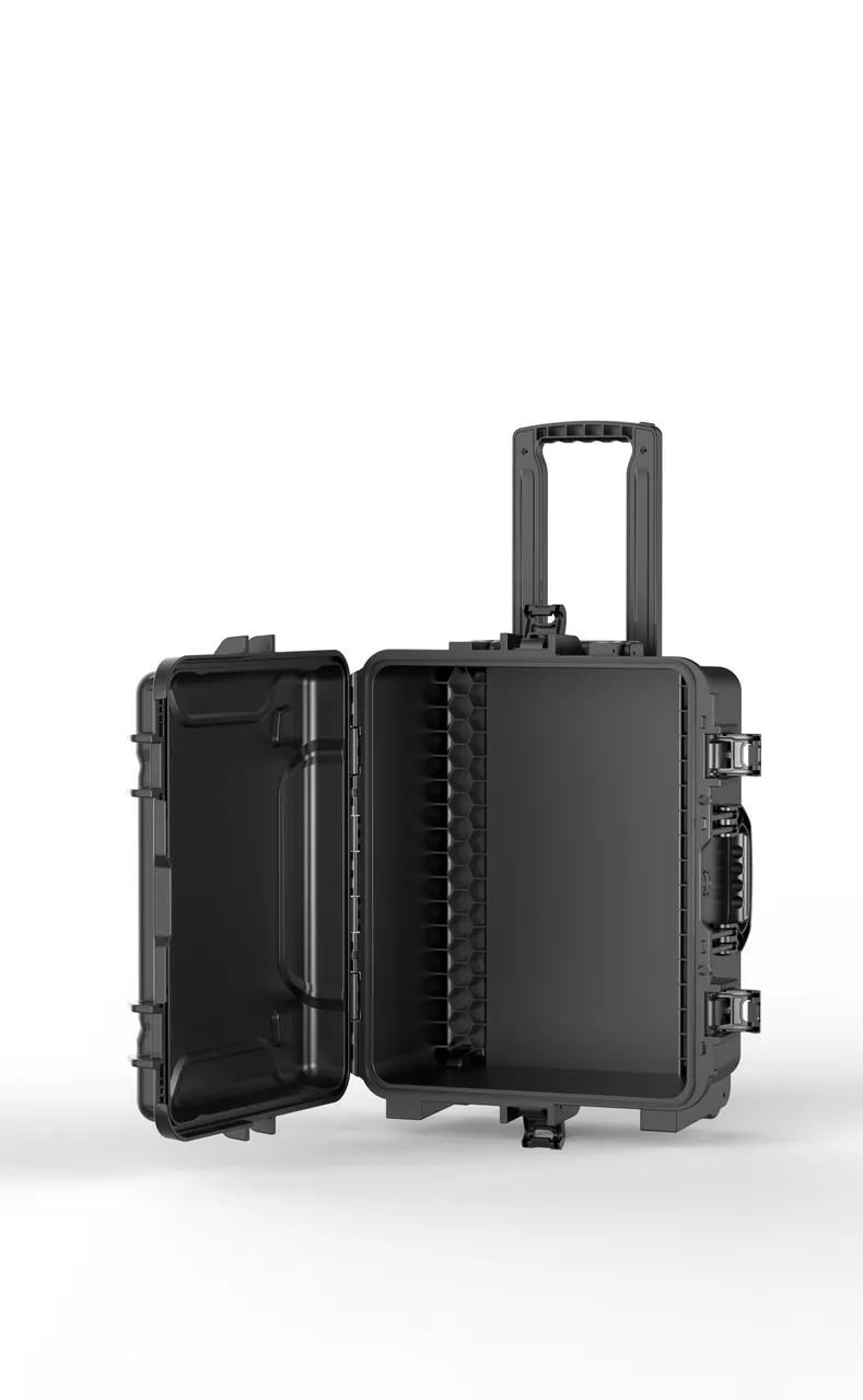
Signal equipment cases typically circulate repeatedly between depots, overhaul bases and spare-parts stores, and high-cycle circulation creates a completely different risk profile from a one-way export shipment.
Four special requirements for circulation use. First, usability first: cases should have casters and telescopic handles for handling efficiency, inserts should be mistake-proof so parts only fit in the correct attitude, and a brief work instruction should be printed inside the lid; see case wheels and trolley handle selection. Second, durability first: frequent opening accelerates gasket and latch fatigue, so choose low-compression-set gasket materials and high-life latches and bring gaskets and latches into a preventive replacement plan. Third, mistake-proofing first: turn critical actions such as removing transport locking devices, loading in the correct attitude and reading the humidity indicator card into checklists posted inside the case. Fourth, track segregation: new equipment, repaired items, items awaiting inspection, accepted items, coastal routes and inland routes should use separate case pools to avoid cross-contamination and mixed use.
Storage management points.
- Environment: keep stores dry and ventilated and out of prolonged sunlight; avoid sharing space with strong magnetic sources such as large transformers, electromagnets and magnetic tools;
- Attitude: store relays and oil-filled equipment in the specified attitude, never inverted;
- Stacking: follow the marked stacking limit and avoid sustained heavy loads that collapse inserts;
- Shelf life: gaskets, moisture-barrier bags, desiccant and batteries have shelf-life or age requirements; apply first-in-first-out and keep age records;
- Re-inspection: before re-despatching after long storage, recheck the humidity indicator card, gaskets and retention state.
Reuse criteria, six items. Before reuse, inspect the case for cracks, deformation and delamination, focusing on corners, the base and caster mounting points; the gasket for hardening, cracking, debonding and permanent compression set; latches and hinges for reliable closing with even force distribution; the insert for collapse, fracture, contamination and shedding; compartment boxes for damage and missing cells; and casters and handles for wear, load capacity and locking function. Any failed item must be replaced before reuse, with criteria discussed in protective case service life. Note in particular that a case previously used to carry damp, oil-leaking or contaminated items must have all inserts and gaskets replaced and be cleaned and assessed for residue, with quality department sign-off, before it carries relays or electronic equipment again.
Case identification system. Keep a log covering case number, use count, purpose, inspection records and desiccant replacement records, and use colour coding and labels as the first line of defence on the shop floor. For lock and seal options see case lock customization options.
14. Procurement evaluation and the OEM/ODM path
Signalling equipment cases are safety-related, standards-heavy, category-diverse and frequently circulated, so procurement strategy should focus on scheme capability, particularly attitude fixing and moisture-control design, and on documentation completeness.
Seven supplier evaluation dimensions.
- Part capture and attitude design. Can the supplier produce a partitioned insert scheme from physical parts or 3D data, and specifically solve three problems: relays compartmentalised in working attitude, an explicit load path for heavy parts, and no load on drive rods or terminals.
- Moisture and sealing capability. Ability to size desiccant from free volume, packaging hygroscopicity, transit duration and target humidity; to fit humidity indicator cards and pressure equalisation valves; and to offer different IP ratings with supporting test records.
- Vibration and retention capability. Ability to define a measurable displacement criterion and to design secondary restraint for contact systems and connectors.
- ESD and cleanliness control. Shedding tendency and migratable ion control for insert materials, plus ESD packaging and handling discipline.
- Material and durability. Gasket cross-section and compression set, latch and hinge fatigue life, which matters most in high-cycle scenarios, insert compression resistance, and temperature range.
- Compliance and documentation. Material declarations, test reports and English-language documents, plus packaging and marking schemes where batteries or regulated goods are involved.
- Capacity and delivery flexibility. Signalling equipment orders are usually tied to line opening schedules, so delivery stability is a real risk. For quality and sampling rules see custom case acceptance and AQL sampling.
The standardise-the-case, customise-the-insert strategy. Signalling equipment varies enormously in size, from relays to point machines, and fully custom cases are uneconomical. The practical approach is to cover most of the size range with three or four standard case types, for example relay cases, electronic module cases, general parts cases and heavy-duty cradle cases, and adapt each with a custom insert. This amortises tooling cost while preserving flexibility as equipment generations change. For tooling cost structure see case mould cost analysis.
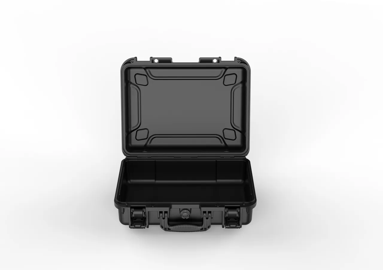
Choosing a general case format. For categories that do not need a heavy cradle, such as relays, terminals, tools and spares, a mature portable transport case format can shorten lead time and reduce cost; the selection logic is covered in portable transport box selection.
Enquiry checklist. A practical enquiry should include the equipment list with model, name, unit weight, envelope dimensions and quantities; whether permanent magnets, oil-filled items, batteries or static-sensitive items are involved; cleanliness and moisture requirements; transport mode and route including transhipment and transit duration; destination climate and storage conditions; target IP rating and whether a pressure equalisation valve is needed; circulation count and scenario; marking and sealing requirements; test and English documentation requirements; and annual volume with delivery rhythm. The more complete the input, the closer the scheme comes to being ready for production. For supplier selection see how to choose a protective case OEM factory.
JUNZHJIA works in this category as follows: accept 3D data or physical parts, produce a partitioned insert and attitude-fixing scheme with retention recommendations, a desiccant sizing calculation and a sealing configuration, confirm with a first-article trial fit, then move to volume production with sampling and supply material declarations and test documentation alongside. For long-term supply customers we maintain model dossiers so repeat orders reuse the existing scheme, and for customers with high-cycle depot circulation we can supply a preventive replacement plan for gaskets, latches and inserts.
Frequently Asked Questions
Q: Why can railway signal equipment not simply use the packaging approach used for general electronic equipment?
A: Because signalling equipment has two sensitivities that ordinary electronics do not. The first is geometric sensitivity. Relay reliability is determined by contact gap, contact pressure, armature travel and magnetic air gap; point machine indication correctness depends on the relative position of the locking block and indication rod; impedance bond performance depends on core lamination clamping and air gap. All of these can shift slightly under shock and prolonged vibration, and the result is not failure but marginality. A marginal state is worse than an obvious fault because it passes self-test, passes bench testing, and then fails intermittently on site when temperature, humidity and vibration combine, with poor repeatability. The second is contamination sensitivity caused by low-energy operation. Many signalling components work at low voltage and very low current, relay contacts carry milliamps and track circuit receivers discriminate millivolt differences, so an invisible oxide film, a particle of dust or a trace of oil can raise contact resistance and eat the signal margin. General electronic packaging considers only cushioning and static discharge, with no humidity control and no protection against contact contamination, which is why it is not suitable here.
Q: What are the three most important measures when shipping safety relays?
A: The first is fixing the attitude. Many relays, especially gravity type and those with mechanical timing mechanisms, have operating characteristics tied directly to mounting orientation, so they must be packed in the transport attitude the manufacturer specifies, never inverted or on their side, with orientation marked on the case. The second is separate compartments with soft surface contact. Relays should be one per cavity with no part touching another, cavity dimensions matched to the envelope to prevent movement, and restraint force distributed through compliant padding rather than applied as a hard point on the housing, contact cover or terminals. The most common error in practice is stacking several relays and packing filler around them, which makes contact covers rub against each other under vibration and transmits impact straight into the contact system. The third is humidity control and magnetic avoidance. Contacts are extremely sensitive to oxide films at low current, so the case needs desiccant sized by free volume and transit duration plus a humidity indicator card, with the factory moisture-barrier packaging retained. Relays containing permanent magnets should also avoid sharing a zone with large transformers, reactors, electromagnets or magnetic tools, since elevated temperatures can cause irreversible magnetic loss. Beyond these three, verify pickup voltage and contact resistance on arrival rather than checking appearance alone.
Q: How does transport protection for heavy mechanical items such as point machines differ from ordinary heavy machinery?
A: The difference comes down to three points. First, a point machine contains mechanism positions that determine a safety function; the fit between the locking block and the indication rod directly determines the correctness of the indication circuit. Protection is therefore not only about preventing impact damage but also about preventing the mechanism from shuttling freely under vibration. Use the manufacturer's transport locking devices, or where none are supplied, provide equivalent restraint through the insert. This is fundamentally different from a general mechanical part, which only needs protection from deformation. Second, exposed rods need much stricter protection. Drive and indication rods are slender and dimensionally critical, and even slight bending produces incorrect indication, so protective sleeves or relief cavities are required, threads and connection holes need caps, and the rods must never serve as load or lifting points. Third, sealing and port requirements are stricter. Point machines contain gearboxes and lubricating grease, so oil ports, breathers and cable entries must be sealed as the manufacturer requires and loaded in the specified attitude with anti-tilt provision so that grease does not migrate where it should not. Heavy cases should also follow the loading principle of heavy below light and large below small, with heavy cases never placed on top of light cases during transhipment.
Q: How should the IP rating be chosen for a railway signal equipment case? Is IP67 safer?
A: Not necessarily. Selection should follow actual exposure. IP ratings are defined by IEC 60529, with GB/T 4208 as the Chinese equivalent. For indoor stores and covered short hauls, IP54 is usually sufficient. Domestic road transport, trackside cabinet storage and dusty sites suggest IP65. Sea freight, open transhipment, high-rainfall regions and coastal routes suggest IP67. Four points deserve attention. First, a higher rating creates a larger pressure differential across temperature swings, making the case harder to open and potentially deforming the gasket under suction, which shortens its life. Second, signalling cases are opened frequently by many people at a depot, so gasket fatigue is much faster than in low-cycle scenarios, and a higher rating implies stricter maintenance. Third, an IP rating only blocks water and particulate from outside; it does nothing about condensation inside, which is the main cause of falling insulation resistance and terminal oxidation. Fourth, higher-rated schemes usually cost and weigh more, which is not always appropriate where the case must be carried frequently. For routes with large temperature differentials, a pressure equalisation valve combined with desiccant and a humidity indicator card is often more effective than raising the IP rating alone. Where a tender specifies a rating, follow the document and require the corresponding test record from the supplier.
Q: Why does adding desiccant so often fail to protect signalling equipment from moisture?
A: Because desiccant quantity and replacement discipline are usually taken casually, with four common failure causes. First, incorrect sizing. Desiccant should be sized from free volume, packaging hygroscopicity, transit duration and target humidity, yet the practice on the floor is often to toss in two sachets. Open-cell foam inserts, paper documentation and cardboard outer packaging all absorb moisture and continuously consume desiccant capacity, and all of that must be included. Second, using the same quantity for sea freight and domestic short hauls. A 30 to 45 day sea voyage needs substantially more than a domestic run, so equipment using domestic quantities is unprotected for the latter part of the voyage. Third, not replacing desiccant when cases are reused. Every opening admits new moisture, so desiccant should be replaced each cycle rather than used until it visibly changes colour; a hidden gasket leak will also accelerate desiccant consumption, which makes consumption rate an indirect indicator of gasket condition. Fourth, the wrong order of operations on arrival. The correct practice is to read the humidity indicator card first and condition the case in a controlled environment if it is out of range, yet the common practice is to open the case in a humid area and leave equipment exposed for hours. Making these four points procedural, particularly writing read the indicator before opening into the work instruction, produces a clear improvement.
Q: Why is a passed power-up self-test not sufficient for goods-in acceptance of signalling equipment?
A: Because the dominant failure mechanism is performance drift rather than loss of function, and self-test only detects loss of function. Self-test routines typically check power supply health, board response, communication establishment and the presence of fault codes, and they are completely insensitive to drift such as a contact gap that has changed by a fraction of a millimetre, contact resistance rising from tens of milliohms to hundreds, insulation resistance falling from hundreds of megohms to tens, or a slight change in magnetic air gap. Those are precisely the changes transport is most likely to introduce, and they are the root of intermittent site failures. A workable acceptance approach converts invisible change into comparable data: record electrical reference values before packing, including relay pickup voltage and current, operating time, contact resistance and insulation resistance; file packing photographs and the seal number after closing; and re-measure the same set of parameters on arrival for comparison. Alongside this, look for three classes of evidence. New contact marks, such as impressions on contact covers or imprints in the insert that do not match the outline. Environmental evidence, such as a discoloured humidity indicator card, oxidised metal terminals or water traces inside the case. And mechanical evidence, such as displacement marks on drive rods, loosened connectors or misaligned locking paint marks. For safety-related equipment this data set is the only reliable basis for separating incoming quality problems from packaging problems and transport problems.
Q: Why do small items such as cables, terminals and connectors cause so many problems in signal equipment shipments?
A: Because they exist in large quantities at low unit value, so processes tend to treat them casually, yet they determine connection reliability directly. Three classes of problem recur. The first is moisture. If a cable end is not properly sealed, moisture wicks along the conductors and insulation resistance falls, often irreversibly; copper terminals and plating oxidise in humid heat and contact resistance rises. End sealing, moisture-barrier bags and desiccant are therefore not optional for these small parts. The second is mechanical deformation. Terminal blocks crush and distort, pins bend on impact, and spring contacts take a permanent set, all of which come from casual packing and are hard to attribute afterwards to either incoming quality or transport. The third is mixed parts and wrong installation. Field experience shows a substantial share of arrival problems come from mixed parts rather than physical damage, usually because compartments and numbering are missing. The countermeasure is to design management into the packaging: use lidded compartment boxes with each cavity labelled with part number and quantity; number both ends of cables and the connectors so they correspond to ports one to one; verify the packing list compartment by compartment rather than by weight; mark spare parts separately to prevent misuse; and record production dates and storage conditions for connector seals and apply first-in-first-out, so that seals do not age and tear at installation.
Q: What are the most common management-related failures in high-cycle depot signalling cases?
A: The three most common are hidden gasket failure, missed transport locking devices and ineffective seal management. First, hidden gasket failure. Frequent opening accelerates gasket fatigue, and a failing gasket usually does not show up as obvious water ingress but as faster desiccant consumption and an out-of-range humidity indicator card. This is a gradual process, and staff rarely connect it to the gasket until a shipment arrives with moisture damage or degraded insulation. The countermeasure is to bring gaskets into a preventive replacement plan and to make reading the humidity indicator card on arrival a procedural step, using desiccant consumption rate as an indirect indicator of sealing condition. Second, missed transport locking devices. Packing involves two directions of action, fitting locking devices and removing them on arrival, and missing either direction causes problems: a device not fitted lets the mechanism shuttle in transit, while a device not removed causes abnormal operation or jamming. Print the work instruction inside the case lid and build in both physical mistake-proofing and checklist verification. Third, seal and lock management. Seals go missing and locks break frequently under high-cycle use, so handover cannot confirm whether the case was opened. Use numbered seals, record the number on the handover sheet, and keep locks and seals on the spare parts list. All three share the property that they do not fail immediately but accumulate risk, so they must be managed by procedure rather than by experience.
Q: We buy relay cases, electronic module cases and heavy-duty cradle cases together. How can packaging and compliance costs be controlled?
A: The core approach is to standardise cases, customise inserts, zone and segregate, number for traceability and front-load compliance documentation. First, divide cases into three or four standard types by internal volume and load rating, so standard cases absorb size diversity and no tooling is needed per item. Second, customise inserts per model; because the cavity is common, inserts remain interchangeable and upgradable, ordered by insert part number. Third, zoning and segregation: relays and electronic items in humidity-controlled cavities, mechanical and heavy items in structural cavities, and separate case pools or colour labels for coastal versus inland routes and for new versus repaired items. Fourth, build a packaging dossier per model containing envelope data, insert drawing number, packing photographs, test records and electrical reference values, so repeat orders reuse the existing scheme; this is the single most effective long-term cost measure. Fifth, front-load compliance documentation: where batteries or other regulated items are involved, confirm at the procurement stage who provides the packaging, marking and declaration inputs and in what form, so that shipments are not delayed by last-minute additions, and clarify whether third-party laboratory reports and English documents are required. Sixth, include reuse cost in the calculation: gaskets, desiccant, inserts, compartment boxes, seals and humidity indicator cards are all wearing or consumable items and should be costed by circulation count under a preventive replacement plan, because the failure of a small component can damage an entire case of equipment.
Conclusion & Further Reading
The essence of railway signal equipment protection is keeping invisible performance drift out of the transport chain: relay contact gap and pressure, the cleanliness of contact surfaces, permanent magnet flux, impedance bond air gaps, point machine indication rod position, contact resistance at terminals and connectors, and the dryness of insulation. None of these appear in an arrival inspection and none surface in a power-up self-test, yet all of them can combine with site temperature, humidity and vibration to produce intermittent failures, by which point responsibility is impossible to establish.
A signal equipment case should therefore be designed along three parallel chains. Environment: sealing, desiccant, humidity indicator cards and pressure equalisation valves to hold internal humidity within target across the whole journey. Restraint: attitude fixing, separate compartments, soft surface contact and mechanism locking to cut the shock and vibration path into contact systems, magnetic circuits and boards. Management: zoning, track segregation, numbering, seals and three-point comparison to turn invisible drift into auditable data. All three are required; a missing link degrades the other two.
The implementation path compresses into five steps: define each item's vulnerable points and cleanliness class, design the attitude-fixing structure and partitioned inserts, close the loop with transport testing plus electrical and mechanical characteristic checks, build a chain of responsibility through numbering, seals and reference-value records, and sustain long-term performance through reuse inspection, desiccant replacement and preventive replacement. Doing these five things is what keeps the "arrives intact, fails intermittently on site" risk to a minimum.
If you need a partitioned insert and attitude-fixing scheme for specific equipment, retention structure recommendations, a desiccant sizing calculation, ESD and humidity-control configurations, or a complete compliance packaging scheme including batteries, provide the equipment list, 3D data, transport route and circulation scenario to JUNZHJIA. We will capture the equipment, produce drawings and arrange a first-article trial fit, delivering a packaging scheme that can go straight into production.
Further Reading