

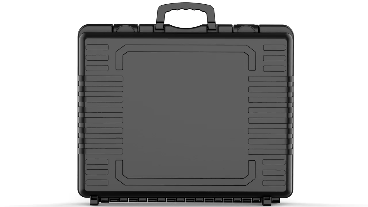
A brickworks is about the least friendly environment a protective case will ever meet. The air carries clay dust, coal-gangue dust and shale dust all day; these particles are fine, hard and electrostatic, and they work into any gap that is not sealed. The shop floor is damp. And the machine's own components are heavy — an extrusion auger, a clay-barrel liner or a cutter carriage runs from tens of kilograms into several hundred. The awkward part is that their precision is not visible in overall dimensions. It hides in a few narrow mating faces: the 1 to 3 mm gap between auger flight edge and barrel wall, the taper fit at the auger shaft end, the liner bore tolerance, the flatness of the cutting-wire frame. Damage to those faces does not announce itself as breakage. It appears as out-of-tolerance brick dimensions, uneven density and a rising breakage rate.
JUNZHIJIA's protection principle for brick machine components is to rank risk in three layers — dust abrasion, heavy load and narrow clearance — and to treat dust ingress as the first priority, load structure as the second, and cushioning only as the third, because once abrasive dust reaches a mating face no amount of foam will recover the accuracy. What follows covers the auger, its shaft end, the clay-barrel liner, the cutting-wire frame, carriage guideways, the vacuum pump set, dust-abrasion packing, lifting and load structure, washing and drying, small-part compartmentation, stacking and banding, and arrival acceptance.
Table of Contents
- Protecting Hard-Faced Auger Flights and Supporting the Screw in Free Air
- Taper Fits and Keyways at the Auger Shaft End: Impact Protection
- Clay-Barrel Liner Bore Tolerance and Fitting Taper Protection
- Preserving the Flatness and Tensioning Mechanism of Cutting-Wire Frames
- Dust Sealing and Impact Protection for Cutter Carriage Linear Guideways
- Dust Plugs for Vacuum Pump and Vacuum Chamber Ports
- Packing for a Dust-Abrasive Environment: Abrasion-Resistant Outer Shell and Dust Ingress Barriers
- Matching Lifting Lugs on Heavy Parts to the Case Load Structure
- Clay Residue Washing, Neutralising and Drying Before Packing
- Compartmented Anti-Loss Packing for Magnetic Separators and Screens
- Stacking, Banding and Transport Load Distribution
- Arrival Acceptance and Layered Spare Parts Management
- Frequently Asked Questions FAQ
- Conclusion and Related Reading
Protecting Hard-Faced Auger Flights and Supporting the Screw in Free Air
The extrusion auger is the heart of a brick machine. Flights are welded to a core shaft, and the outer edge carries a 3 to 6 mm high-chrome hard-facing overlay at HRC 55 to 60. The flight outside diameter stands only 1 to 3 mm clear of the barrel wall, and that gap governs extrusion pressure and column density. Once a block of overlay breaks away, the gap opens locally, material backflows at that point, and the symptom is a helical streak on the column surface, uneven density and, in bad cases, delamination.
The single most important packing rule is that the flights must float free. The overlay at the flight edge is the most brittle feature on the whole auger and the one most casually laid down when a case is loaded. Support the screw from the journals at both ends, with the flight edge standing at least 30 mm clear of the case floor. If a long auger needs a mid support, put it on the core shaft using a block with a half-round groove rather than anywhere near a flight.
The same logic governs stacking. Two augers must never touch flight to flight; interpose a rigid PE divider of at least 30 mm covering the full bearing footprint of the flight outside diameter, so loading is distributed rather than concentrated. Orient the screw flights-up with the core shaft parallel to the case long edge, so a lateral impact loads the flight radially, along its stiffest direction, rather than axially, along its weakest.
| Zone | Material and hardness | Dominant failure | Packing measure |
|---|---|---|---|
| --- | --- | --- | --- |
| Flight-edge overlay | High-chrome hard-facing, HRC 55-60 | Block breakout, crazing | Floating 30 mm clear of hard faces |
| Flight root weld | Carbon steel weld | Cracking, weld failure | Kept out of impact paths |
| Core-shaft journal | Quenched and tempered, ground | Scoring, corrosion | Half-round cradle plus boot |
| Flight-to-barrel face | Hard-facing | Accelerated local wear | Rigid interlayer dividers, layer limit |
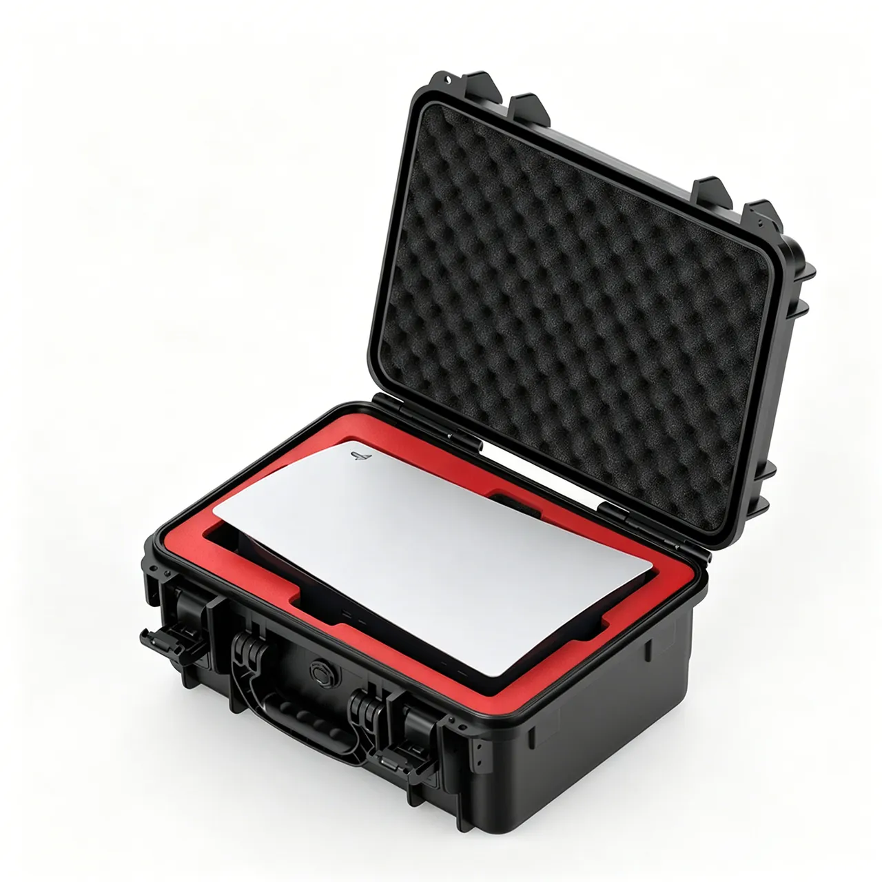
An extrusion auger is a classic hard-face-and-narrow-clearance assembly, and its protection logic follows ceramic tile machinery and crushing and screening equipment. Ceramic tile machinery cases and crushing and screening parts cases set out how to choose support points for high-hardness parts inside a case.
Taper Fits and Keyways at the Auger Shaft End: Impact Protection
The auger shaft end normally couples to the gearbox output or a coupling through a taper fit, usually 1:10 or 1:20, with a contact ratio requirement of at least 75 percent. A keyway and key carry the torque, with fits typically between 0.02 and 0.08 mm. Both features fall into the category where one knock means rework.
Taper faces fail differently from flat faces. A taper transmits torque and holds coaxiality through large-area conformity, so once a press mark or burr appears the contact ratio falls, and after assembly the symptom is increased radial runout during rotation, which in turn makes the auger-to-barrel gap vary cyclically. Protect the taper with a rigid plastic boot matched to the angle, with a 0.5 mm soft liner inside and the mouth taped shut. Plug the keyway with a soft insert projecting 5 mm so a technician can pull it out.
On transport attitude, keep the shaft end up or to the side. If it must point down, separate it from the case floor with a rigid support block rather than letting the boot carry load. At incoming inspection, a red-lead contact check is the most direct method: coat the taper, rotate one full turn, and read the contact pattern. Blotches should distribute evenly around the circumference, and any missing region above 25 percent means the taper needs lapping.
Clay-Barrel Liner Bore Tolerance and Fitting Taper Protection
The clay-barrel liner sits inside the extrusion barrel and, together with the auger flight edges, forms the extrusion chamber. Bore tolerance is usually H8 to H9; the bore surface is integral wear-resistant cast iron or segmented wear plates; and the outside locates into the barrel on a transition fit, positioned by an end pressure ring or a taper. Liner failures are almost entirely bore distortion and fitting-face damage.
Bore protection is about preventing ovality. A thin-wall liner, meaning wall thickness under 8 percent of bore diameter, lying on its side under stack load will ovalise within hours. Liners must therefore travel with the axis vertical, carried on an annular seat at the base with nothing heavy resting on top. Where a liner must lie flat, insert a support ring matched to the bore to hold roundness; turn the ring from rigid PE with an h8 outside tolerance.
Fitting faces, meaning the outside locating band and the end face, need individual protection. Wrap the outside in 2 mm rubber membrane and fit a 3 mm PP annular cover plate to the end face. For segmented liners, pack each segment in its own cell with a position number, because segments differ slightly in curvature and a misplaced segment leaves a local gap.
| Zone | Accuracy | Dominant failure | Protection |
|---|---|---|---|
| --- | --- | --- | --- |
| Bore working surface | H8-H9 | Ovality, scoring | Vertical stance or support ring |
| Outside locating band | Transition fit | Impact marks, press marks | Rubber membrane plus ring cover |
| End locating face | Flatness 0.05 mm | Chipping, corrosion | PP cover plus rust-preventive grease |
| Segment arc face | Matched to barrel curvature | Wrong position, abrasion | One cell per segment plus numbers |
Preserving the Flatness and Tensioning Mechanism of Cutting-Wire Frames
The cutting-wire frame slices the continuous clay column into fixed-length bricks, and wire flatness directly sets end-face squareness and length tolerance. A frame normally combines the frame body, tensioning shaft, spring or pneumatic tensioner and a set of wires, with frame flatness usually held within 0.5 mm. The three damage modes in transit are frame torsion, tensioning shaft bowing, and wires crushed or rusted through.
Handle it as: frame fixed first, wires packed separately, tensioner released. Fix the frame on four support points at its corners so nothing spans unsupported. Release the tensioner completely before shipment, relaxing springs or venting cylinders so the tensioning shaft sits free; a tensioner left loaded will fatigue shaft-end threads or pin holes under transport vibration. Wires are best coiled separately, each into a ring of at least 300 mm diameter, secured with a soft tie, grease-filmed and bagged in VPI paper. If the customer requires wires fitted at dispatch, add temporary spreader bars inside the frame to hold them tensioned and label the case clearly with an instruction not to remove the bars before the case is inside the plant.
On arrival, flatness is the first check. Lay the frame on a surface plate and check corner gaps with a feeler gauge; anything above 0.5 mm means the frame has deformed and needs levelling before wires go on. Check tensioning shaft straightness with a dial indicator at mid-span and replace the shaft above 0.2 mm of runout.
| Part | Accuracy | Dominant failure | Packing measure |
|---|---|---|---|
| --- | --- | --- | --- |
| Cutter frame | Flatness 0.5 mm or less | Torsional distortion | Four-point support, no mid loading |
| Tensioning shaft | Runout 0.2 mm or less | Bowing, thread damage | Fully released before shipment |
| Spring or cylinder | Stroke accuracy | Fatigue, seal damage | Venting plus separate packing |
| Cutting wires | Straightness | Crushing, corrosion | Ring coils in VPI paper bags |
| Wire clamps | Grip accuracy | Tooth damage, loss | Compartmented and numbered |
Dust Sealing and Impact Protection for Cutter Carriage Linear Guideways
The cutter carriage reciprocates along linear guideways, and guideway straightness plus block preload decide cut squareness and cut quality. Guideways are acutely dust-sensitive: clay dust between block and rail acts as an abrasive, producing dense longitudinal scoring and growing clearance.
The primary task is dust exclusion rather than impact protection. Cover the full rail length with a 0.5 mm elastic sealing strip clamped at both ends to form a continuous curtain, and wrap the block in self-adhesive protective film with the air expelled. Where scraper plates are already fitted, add a temporary protective band outside the scraper lip so the lip does not pack with dust and lose its elasticity.
On impact, park the carriage mid-travel and fix it with limit blocks so the block cannot slam into the rail end, which is the travel limit and repeated stops there damage screw or rack end teeth. Protect tool clamping and locating faces with cover plates, and pack cutting blades separately.
Servo-driven machines with ball screws need two extra precautions. First, the screw needs higher dust protection than the rail: dust packed into screw grooves compacts into hard lumps in reciprocating motion and backlash grows quickly, so enclose the screw in a bellows cover clamped at both ends. Second, the servo motor and encoder must not be supported from the case floor; carry the motor from its mounting flange on compliant blocks so the coupling disc pack between motor and screw sees no axial compression. A compressed disc pack deforms permanently, and the symptom is lost positioning accuracy with a completely normal appearance.
Dust Plugs for Vacuum Pump and Vacuum Chamber Ports
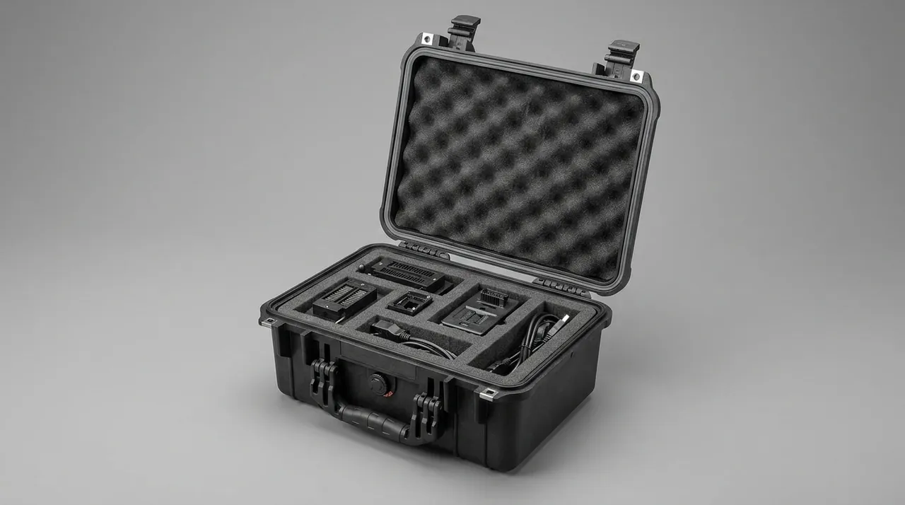
Hard-plastic extrusion brick machines commonly use vacuum extrusion, and the pump set, vacuum chamber and vacuum piping form a sealed system where leakage matters. Transport protection has three requirements.
First, plug the ports. The chamber extraction port and the pump inlet and outlet must be closed with gasket-sealed plugs secured by ties so nothing falls out and lets dust into the pumping chamber. Second, manage rotor clearance and lubrication. Water-ring impeller-to-casing clearance and Roots impeller clearance sit around 0.1 mm, so axial shock must be prevented; pack the pump in its own compartment with axial limit blocks. A water-ring pump must also have its working liquid drained before shipment, otherwise sloshing drives liquid into the bearing cavity and emulsifies the grease. Third, protect instruments. Vacuum gauges are precision items needing their own cell and vibration isolation.
Vacuum piping deserves a note of its own. It is often fabricated on site, and where it ships with the machine it behaves like any long part: support pitch no greater than 1200 mm, both ends capped, and the pipe body never used as a load path for other components. Shaft and coupling parts take the same treatment described in shaft coupling and shaft part packing.
Packing for a Dust-Abrasive Environment: Abrasion-Resistant Outer Shell and Dust Ingress Barriers
Brickworks dust has three characteristics that matter: it is fine, it is hard, and it carries static charge. Clay and coal-gangue dust sit between 2 and 7 on the Mohs scale, and the quartz content in gangue reaches 7. Once such particles reach a case sealing face they act like lapping compound and wear the gasket continuously. Case design for a brickworks therefore has to weight external abrasion resistance and sealing reliability more heavily than a general workshop case would.
For external abrasion, take either of two routes. One is a shell material with higher surface hardness, or protective patches bonded specifically at base and corners, where floor grit does its damage. The other is replaceable wear strips on the outside, 3 mm polyurethane, swapped out once worn. For sealing, aim for IP65 or better to IEC 60529 and specify a gasket in silicone or EPDM that resists dust abrasion, in a groove with a dual-lip plus outer dust-lip profile: the outer lip blocks dust, the inner lip blocks moisture.
Clean the shell as well. Dust left on a case absorbs atmospheric moisture and forms a weakly alkaline or acidic wet film that accelerates plastics ageing. An anti-soiling coating on the exterior, or a full dust cover fitted before dispatch and removed on arrival, handles this at very low cost. The filtration and housing practice in dust collector equipment cases is a useful reference, since those units face the same dust load in continuous service.
| Layer | Measure | Purpose | Cost level |
|---|---|---|---|
| --- | --- | --- | --- |
| Outer abrasion | Polyurethane strips, thickened corners | Resists floor grit | Low |
| Seal against dust | Dual-lip gasket with dust lip | Blocks fine particles | Medium |
| Part-level barrier | VCI film plus VPI paper | Protects machined faces | Low |
| Internal clean | Blow-down plus desiccant | Cuts internal dust and moisture | Low |
| Cover | Full dust cover | Prevents in-transit accumulation | Low |
Matching Lifting Lugs on Heavy Parts to the Case Load Structure
Brick machine components span a wide mass range: a cutting-wire frame may weigh 30 kg while a 3000 mm auger passes 400 kg and a complete clay-barrel liner reaches 600 kg. One case design cannot cover that spread, so load structure has to be banded by weight.
The fundamentals match mixer components, with one brickworks-specific addition: lug positions must align with the case load beams, and the lugs themselves must be rated at twice the working load. The reason is that brick machine parts often travel with their factory lugs attached, and the site lifts directly from those lugs. If the case lifting points sit off the part's lug line, the part swings inside the case and strikes its neighbours.
Band the structure as follows. Under 50 kg per piece, a locally reinforced base is enough. From 50 to 200 kg, use two full-length base beams. From 200 to 500 kg, three full-length beams plus local reinforcing plates. Above 500 kg, move to a steel base frame mated to the case, where the case provides only protection and dust sealing and all mass transfers through the frame to the pallet or container floor. Heavy cases travel as a single tier with nothing stacked on top.
| Piece weight | Base structure | Lifting | Stacking tiers |
|---|---|---|---|
| --- | --- | --- | --- |
| Up to 50 kg | Reinforced base | Manual or small yoke | 3 |
| 50-200 kg | Two full-length beams | Two-point lift | 2-3 |
| 200-500 kg | Three beams plus plates | Two or four-point lift | 2 |
| Above 500 kg | Steel base frame plus case | Four-point, lugs verified | 1 |
Clay Residue Washing, Neutralising and Drying Before Packing
Components pulled out of a brickworks almost always carry clay slurry. Once dry it forms a hard shell over a damp interface, and if the part is boxed without cleaning, that interface rusts steel evenly within weeks while the dry shell sheds dust into the case.
Sequence the cleaning wet first and dry second, coarse first and fine second. Begin with a high-pressure water wash to remove the bulk of the slurry, keeping the jet away from bearing journals and taper faces. Then brush mating faces and grooves with a neutral detergent to remove residual clay. Follow with a mildly acidic neutraliser for alkaline residue, since mixed clay and cement residue often exceeds pH 10, and rinse clean. Finally blow out grooves and bolt holes with compressed air and bake at 60 degrees Celsius for two hours until the surface is completely dry.
Move to rust prevention within four hours of drying. The approach matches other heavy parts: 0.1 to 0.2 mm of rust-preventive grease on mating faces, whole-item VCI film wrapping, and desiccant inside the case at 200 to 250 g/m³ for silica gel or 100 to 150 g/m³ for calcium chloride composite. One exception matters: hard-faced wear surfaces are cleaned only and never greased, because grease traps dust and carries it back into the extrusion chamber on the next start-up.
Compartmented Anti-Loss Packing for Magnetic Separators and Screens
A brick production line carries a long list of small parts: magnetic separator blocks and spacers, vibrating screen meshes and tensioning plates, auger flight bolts, gaskets and clamps. Individually they are inexpensive, but one missing item stops reassembly dead.
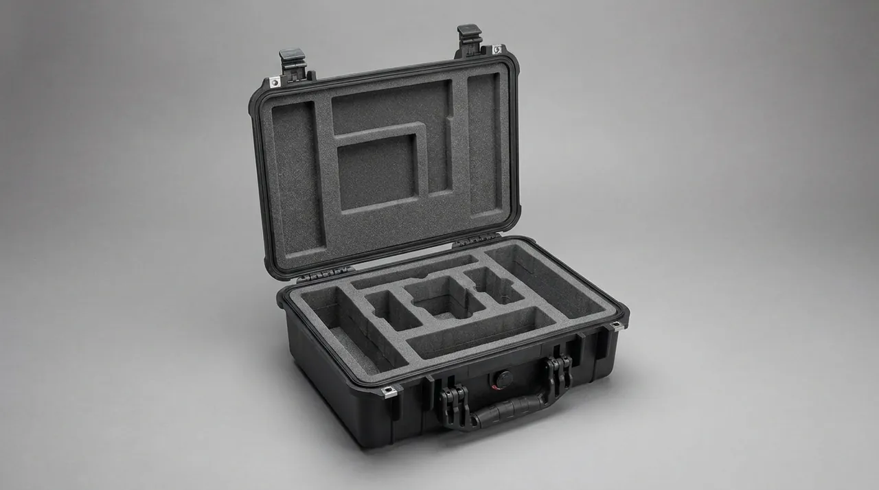
Compartment design follows one item per cell, grouped by function. Magnetic separator blocks are strongly magnetic and must sit at least 50 mm from any ferromagnetic part in their own non-magnetic compartment, separated by aluminium or plastic dividers, so they cannot attract swarf or knock together and lose strength. Screen meshes are thin and large, so they stand vertically in dedicated slots with soft padding at the bottom to prevent face damage, following the mesh handling method in vibrating screen component cases. Fasteners go into bins by size, each labelled with specification and quantity against the shipping manifest.
For the parts most often lost on site, meaning O-rings, retaining clips, dowels and copper washers, provide a dedicated spares box with a transparent compartmented lid and a contents list bonded inside. Open that box first and reconcile it before touching anything else; the habit measurably reduces losses.
One further group deserves attention: auger flight bolts. These are high-tensile fasteners, and on a single auger the bolts are often the same specification but different lengths because flight thickness varies. Mixed in one bag, they are easily confused by feel. Bag them by auger serial number, labelled with long and short quantities, and keep each bag in the same compartment as its auger so multiple augers in one case never lead to cross-fitted bolts.
Stacking, Banding and Transport Load Distribution
Brick machine components move mainly by road, with sea freight for export projects. Road transport combines high-frequency vibration with frequent acceleration and braking; sea freight adds sustained stacking and humidity. The two need different settings.
On the road, the priority is preventing movement. Lay anti-slip matting between case and vehicle floor, cross-band cases with strapping or nylon belts, and route bands around corner protectors rather than over bare edges. Above 300 kg per case, use ratchet tensioners anchored to the vehicle floor lashing rings instead of relying on case-to-case pressure. At sea, the priority shifts to stack load and moisture: heavy cases go at the bottom with top load within the design value, desiccant and humidity indicator cards go inside, and the case is built to IP65 or better with a pressure equalisation valve.
| Scenario | Main risk | Measure | Criterion |
|---|---|---|---|
| --- | --- | --- | --- |
| Short road legs | Vibration, movement | Anti-slip mat plus cross banding | Relative movement 10 mm or less |
| Long road legs | Cumulative vibration, fatigue | Ratchet tie-down plus corner protectors | No crushing at tie points |
| Rail | Longitudinal shock | End stops plus heavier banding | No end displacement |
| Sea freight | Stack load, moisture | Bottom tier plus desiccant | Indicator card unchanged |
| Multimodal | Repeated handling | Steel base frame plus lugs | No corner cracking |
Arrival Acceptance and Layered Spare Parts Management
Brickworks sites rarely have precision measuring equipment, so the acceptance form should be built around criteria you can see and touch rather than instruments.
Cover at least the following: gasket integrity and any sign of dust ingress, humidity indicator card status, hard-facing for block breakout judged visually and by tap test where a dull note suggests internal cracking, auger shaft-end taper for press marks checked by red-lead contact ratio, liner bore ovality measured at three positions with an internal micrometer and compared against half the tolerance band, cutting-wire frame flatness by feeler gauge, carriage guideways for longitudinal scoring, vacuum pump free rotation by hand, and the small-parts box reconciled against its list.
Manage spares in layers by consumption rate. Augers, clay-barrel liners and cutting wires are fast-consumable, so store them separately with position labels. Vacuum pump seals and O-rings have a shelf life, so keep them out of light and heat and label the cure date. Magnetic separator blocks are sensitive to impact and to magnetic interference, so keep them in a non-magnetic case of their own. These heavy-duty shells, compartmented liners and acceptance document sets are produced and inspected to brick machine component drawings by Kexin New Materials (Guangdong) Co., Ltd.
Frequently Asked Questions FAQ
Q: Can a chipped auger hard-facing overlay be repaired by welding on site?
A: Yes, but only if the procedure is followed, otherwise the repair becomes the next crack origin. Grind the chipped area into a gentle slope, remove material until dye penetrant shows no further indication, preheat to 250 to 350 degrees Celsius using the original hard-facing consumable, then deposit in short staggered passes with each layer no thicker than 3 mm. Cool slowly and stress relieve afterwards. A correctly repaired zone recovers roughly HRC 55, but its heat-affected toughness stays slightly below the original, so repairs should avoid the outermost flight edge and the section where auger-to-barrel clearance is most sensitive. Where the chip exceeds 60 percent of overlay thickness, or several flights are affected, replace the flights rather than patching them point by point. Record the repair location and date in the machine log and re-inspect the repaired flights at the next scheduled liner change, because a correctly preheated repair is stable while one deposited cold is not.
Q: A clay-barrel liner bore has a burr after transport. Can it still be used?
A: It depends on position and height. A burr in the working section standing more than 0.3 mm proud will score the clay column and accelerate local wear, so it must be stoned circumferentially in the direction of material flow; afterwards measure the bore at three positions with an internal micrometer and confirm the spread stays within half the tolerance band, with no step left at the dressed area. A burr in the non-working end section can be dressed simply and returned to service. Where the impact has deformed the bore plastically, meaning ovality is measurably out of tolerance, the liner is unusable: deformation destroys the uniform clearance between auger and barrel, which shows up directly as uneven column density and a higher breakage rate. Keep the measurement record with the machine. Where a bore is marginal but still within half the tolerance band, watch column dimensions closely through the first production shift rather than assuming the liner is serviceable.
Q: All the cutting wires snapped after transport. Why?
A: In the overwhelming majority of cases the tensioner was not released. If springs or cylinders are still loaded during shipment, the wires see alternating stress; the peak stays below static tensile strength but sits well above the fatigue limit, so they fail after a few thousand to a few tens of thousands of cycles, which is exactly what one road journey delivers. A second cause is too tight a coil radius, where bending stress adds to tensioning stress. The fix is to release the tensioner completely, coil each wire into a ring of at least 300 mm diameter, wrap in VPI paper, and ship separately. Where pre-fitted wires are required, fit temporary spreader bars inside the frame and label the case so nobody removes them before the frame is inside the plant. Check wire tension evenly across the frame within the first hour of running; uneven tension is the earliest sign that the frame still carries a twist from transport.
Q: What preparation does a vacuum extruder pump need before shipment?
A: Work through four steps. First, drain the working liquid: a water-ring pump must be emptied completely, because sloshing in transit drives liquid into the bearing cavity, emulsifies the grease and produces bearing noise shortly after arrival. Second, plug the ports: inlet, outlet and chamber extraction port all close with gasket-sealed plugs secured by ties so dust cannot enter the pumping chamber or piping. Third, protect the rotor: pack the pump in its own compartment with axial limit blocks, because water-ring impeller-to-casing clearance and Roots impeller clearance are both around 0.1 mm and axial displacement scores the end faces. Fourth, segregate the instruments: vacuum and pressure gauges are precision items needing their own cells and vibration isolation. Finally, photograph the drained pump interior and the capped ports before the case closes, so any liquid or dust found on arrival can be attributed to a specific leg of the journey instead of being debated between supplier and site. Where a spare pump ships with the machine, pack it identically so the two can be compared later.
Q: What special requirements does brickworks dust put on the case?
A: Brickworks dust is fine, hard and electrostatic, and the quartz content in gangue and shale reaches Mohs 7, so once it reaches a sealing face it wears the gasket like lapping compound. Two requirements follow. Externally, the case needs abrasion resistance: replaceable 3 mm polyurethane strips at base and corners are the cheapest effective measure. On sealing, specify silicone or EPDM gaskets that resist dust abrasion and use a groove profile with dual lips plus an outer dust lip, so the outer lip blocks particles while the inner lip blocks moisture, achieving IP65 or better to IEC 60529. Before dispatch, blow the case down and fit a full dust cover, because dust left on the shell absorbs moisture and accelerates plastics ageing during a long voyage. Where the site runs an aggressive washdown routine, consider a thicker or polyurethane-lined outer shell, since repeated wet cleaning is harder on plastics than the dust itself. Whichever grade is chosen, keep one spare gasket set with every case.
Q: How should one brick machine's components be split across cases?
A: Apply three rules in order: band by weight, group by stiffness, isolate by precision. First, sort every component into under 50 kg, 50 to 200 kg, 200 to 500 kg and above 500 kg; anything above 500 kg travels on a steel base frame case or an open pallet. Second, group by stiffness: rigid parts such as augers and barrel liners may share a case, but only with rigid dividers between them and the flights floating free, while low-stiffness items such as wire frames, screen meshes and thin covers need their own case and must never share with heavy parts. Third, handle precision parts individually: shaft-end tapers, liner bores and guideway faces each get a boot or cover plate before being compartmentalised. Small parts go into one spares box that ships with the machine. Then weigh and label each closed case before dispatch, because calculated and actual mass diverge quickly once dunnage, dividers and documents are counted.
Q: What extra protection is needed for sea freight exports?
A: Add four items on top of the road-transport scheme. First, moisture control: set silica gel at 250 g/m³ or calcium chloride composite at 150 g/m³, add 20 percent for voyages beyond 30 days, and place two humidity indicator cards, one near the viewing window and one at the base. Second, sealing and pressure equalisation: build to IP65 or better with a pressure equalisation valve so day-night temperature swings cannot breathe damp air into the case. Third, upgraded rust prevention: 0.15 to 0.2 mm of grease on all machined mating faces plus VCI film wrapping with the air expelled. Fourth, load re-verification: confirm the stacking tier count against residual deflection after a 48 hour static test, with top sag limited to 1/200 of span. Document the outcome of every voyage, because two or three shipments on the same route turn desiccant figures and gasket choices from estimates into validated standards. Keep one master case marked as the reference pack for future shipments.
Q: What lead time and minimum order quantity apply to a custom brick machine case?
A: Lead time depends on whether tooling is needed and how complex the load structure is. With an existing standard case and only EVA compartment liners, the run from drawing approval to first shipment is normally 15 to 25 days. A new injection mould adds 30 to 45 days for toolmaking and trials. A case needing a steel base frame, lifting lugs or replaceable wear strips adds roughly 10 days for welding and load verification. Minimum order quantity is banded by case type: standard sizes start at 50 to 100 units, newly tooled sizes at 200 to 300. For a single machine, bridge with a standard case and custom liner.
Conclusion and Related Reading
Brick machine packing comes down to the order of three jobs: keep abrasive dust outside, put the mass onto a designed load path, and only then absorb what impact remains with foam. Flights float, liners stay round, wire frames ship slack, pump ports stay plugged. JUNZHIJIA builds heavy-duty liners, steel base frames and acceptance document sets to your drawings.
Related Reading